CETAC LSX-213 User manual

CETAC
LSX-213 Laser Ablation System
Manual Part Number 480141 Rev 2e
Operator’s Manual

COPYRIGHT
© 2006-2010 CETAC Technologies
480141 Rev 2e, December, 2010
CETAC Technologies authorizes its customers
to reproduce, transmit, or store this document
in its entirety, including this page, for the
express purpose of installing, operating, or
maintaining the product described herein.
CETAC Technologies
Customer Service & Support
14306 Industrial Road
Omaha, Nebraska 68144, USA
Phone (800) 369-2822 (USA only)
Phone (402) 733-2829
Fax (402) 733-1932
E-mail custserv@cetac.com
REVISIONS
CETAC Technologies strives to provide the
scientific community with an unparalleled
combination of effective technology and
continuing value. Modular upgrades for
existing instruments will continue to be a
prime consideration as designs progress.
CETAC Technologies reserves the right to
revise this document and/or improve
products described herein at any time without
notice or obligation.
TRADEMARK ACKNOWLEDGEMENTS
Windows is a registered trademark of
Microsoft Corporation in the United States and
other countries.
PharMed and Tygon are registered
trademarks of Saint-Gobain Performance
Plastics.
DuPont™, Kapton®, Teflon®, Tefzel® and
Viton® are trademarks or registered
trademarks of E.I. du Pont de Nemours and
Company.
All other marks are the property of their
respective owners.

3
Contents
1Introduction ..............................................................................................................7
Overview.................................................................................................................................... 7
Principles of Operation ....................................................................................................... 8
Laser Ablation Processes............................................................................................. 8
System Overview ............................................................................................................ 8
Laser Ablation System.................................................................................................. 9
Laser Head and Optics ...............................................................................................10
Laser Characteristics..................................................................................................10
Viewing Optics and Video System..........................................................................11
Sampling System ..........................................................................................................11
Computer Hardware and Software.......................................................................11
System Characteristics...............................................................................................12
Options .............................................................................................................................12
Laser and High Voltage Safety Features.............................................................12
Laser Ablation System Components ...........................................................................12
Who Should Use This Product—Operator Qualifications..................................13
Where to Go for More Information..............................................................................13
Preparing for Installation.................................................................................................14
Ventilation ......................................................................................................................14
2Using the LSX-213 Laser Ablation System................................................... 15
Establishing Optimal Operating Conditions ............................................................15
Creating the Lab Environment ...............................................................................16
Replacing Laser Ablation System Components ................................................17
Purchasing Supplies....................................................................................................17
Connecting the Laser Ablation System.......................................................................18
Connections to the Host Computer........................................................................18
Connections to the Power Supply/Cooler...........................................................19
Gas Connections............................................................................................................20
Using the Laser Ablation System ..................................................................................20
Front Panel Indicators...............................................................................................20
Starting the Laser Ablation System .............................................................................21
Methods of Analyses...........................................................................................................22
Optimization ..........................................................................................................................23
Bulk Analysis..................................................................................................................24
Elemental or Spatial Mapping................................................................................24
Depth Profiling..............................................................................................................25
Sample Preparation............................................................................................................26
Sample Size.....................................................................................................................26
Surface Conditions.......................................................................................................26
Powder Samples ...........................................................................................................26
Shutting Down the Laser Ablation System...............................................................28

CETAC LSX-213 Operator’s Manual
Contents
4
3Using the DigiLaz III Software..........................................................................29
What’s New ............................................................................................................................29
Software Overview .............................................................................................................29
Installing the DigiLaz III™Software .............................................................................30
Running the DigiLaz III™Software...............................................................................31
Essential Tasks .....................................................................................................................32
Emergency Stop............................................................................................................ 32
In Case of Electrical Hazard.................................................................................... 32
Starting the Laser Ablation System...................................................................... 32
Shutting Down the Laser Ablation System ........................................................ 33
Menus in the DigiLaz III™Operating Software........................................................33
General Operations ..................................................................................................... 33
Gas Management ......................................................................................................... 37
Video Operations.......................................................................................................... 40
Light Controls................................................................................................................ 42
Using the Sequence Editor ..............................................................................................43
General............................................................................................................................. 44
Sequence ......................................................................................................................... 45
Help ................................................................................................................................... 46
Drawing and Editing Method Graphics .....................................................................46
Drawing a Method Graphic ..................................................................................... 46
Deleting a Method Graphic...................................................................................... 47
Editing a Method Graphic ........................................................................................ 47
Setting Method Parameters..................................................................................... 48
Triggering and Timing ......................................................................................................48
Gas Blank ........................................................................................................................ 49
Pause Between Samples............................................................................................ 49
Trigger Delay ................................................................................................................ 49
Examples .................................................................................................................................49
Service Calibration Tools.................................................................................................50
4Software Methods .................................................................................................51
Spot Scan.................................................................................................................................51
Description ..................................................................................................................... 51
Parameters..................................................................................................................... 51
How to Draw ................................................................................................................. 51
Example........................................................................................................................... 52
Line Scan .................................................................................................................................52
Description ..................................................................................................................... 52
Parameters..................................................................................................................... 52
How to Draw ................................................................................................................. 52
Example........................................................................................................................... 53
Segmented Line Scan.........................................................................................................53
Description ..................................................................................................................... 53
Parameters..................................................................................................................... 53
How to Draw ................................................................................................................. 54
Example........................................................................................................................... 54
Line Raster .............................................................................................................................55
Description ..................................................................................................................... 55
Parameters..................................................................................................................... 55
How to Draw ................................................................................................................. 55
Example........................................................................................................................... 56
Scanning ..................................................................................................................................56

CETAC LSX-213 Operator’s Manual
Contents
5
Description .....................................................................................................................56
Parameters.....................................................................................................................56
How to Draw..................................................................................................................56
Example ...........................................................................................................................57
Area Raster.............................................................................................................................58
Description .....................................................................................................................58
Parameters.....................................................................................................................58
How to Draw..................................................................................................................58
Example ...........................................................................................................................59
Depth Profiling......................................................................................................................60
Parameters.....................................................................................................................60
How to Draw..................................................................................................................60
Example ...........................................................................................................................61
Multiple Method Drawing................................................................................................62
Sequence Editor ...................................................................................................................63
5Maintaining the Laser Ablation System ....................................................... 65
Safety Systems/Maintenance Schedule .....................................................................65
Safety System Inspection .................................................................................................66
Cooling System Maintenance..........................................................................................66
Periodic Checks of the Cooling System ................................................................67
Filling and Draining the Power Supply ...............................................................67
De-Ionizing Cartridge Maintenance (Inline Filter) ........................................69
De-Ionizing Cartridge Maintenance (Internal Filter) ...................................70
Internal Tubing Replacement.........................................................................................74
6Troubleshooting the Laser Ablation System.............................................. 75
Power System Problems...................................................................................................76
Fuses..........................................................................................................................................77
Interface Problems..............................................................................................................78
RS-232 Cable Problems..............................................................................................78
Stepper Interface Cable Problems.........................................................................78
Software Configuration Problems.........................................................................78
Safety Interlock Problems................................................................................................79
Laser module interlocks ............................................................................................79
Laser Controller Interlocks ......................................................................................79
Laser Problems.....................................................................................................................80
No Laser Output ...........................................................................................................80
Low Laser Efficiency ...................................................................................................81
Carrier Gas System..............................................................................................................82
Contamination ..............................................................................................................82
Returning the Product to CETAC for Service...........................................................83
Shipping the Product..................................................................................................83
Product Warranty Statement .................................................................................83
Returned Product Procedures.................................................................................84
Returned Product Warranty Determination ....................................................85
7Safety and Regulatory Information ............................................................... 87
Characteristics ......................................................................................................................87
Environmental Characteristics...............................................................................87
Safety Notices ........................................................................................................................89
Laser Safety....................................................................................................................89
U.S. Regulations – Class 1 Laser Product............................................................89

CETAC LSX-213 Operator’s Manual
Contents
6
CDRH Laser Product Regulations.......................................................................... 89
Coolant............................................................................................................................. 90
Ventilation...................................................................................................................... 90
Power Cord Set Requirements ................................................................................ 90
Power Cord Safety Maintenance ........................................................................... 90
Mains Disconnect......................................................................................................... 90
Cleaning Instructions ................................................................................................. 91
Operating Environment ............................................................................................ 91
Explanation of Caution and Warning Notices ................................................. 92
Avertissements en Français............................................................................................93
Electromagnetic Interference........................................................................................94
Explanation of Regulatory Marks.................................................................................95
8Glossary....................................................................................................................97
7
1Introduction
Overview
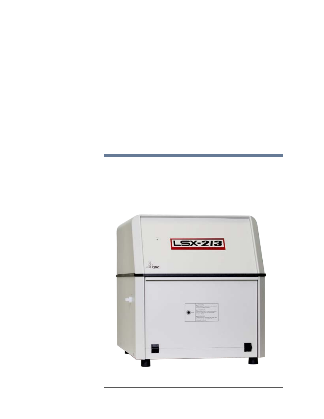
The CETAC LSX-213 Laser Ablation System is the next generation UV laser
ablation system from CETAC Technologies. The LSX-213 system features a
high-energy 213nm laser, with improved viewing optics and an improved
version of the operating software, DigiLaz™ III.
The LSX-213 system is a self-contained solid sampling accessory that can be
installed on any ICP-OES or ICP-MS.
Figure 1-1 The LSX-213 Laser Ablation System.

CETAC LSX-213 Operator’s Manual
Chapter 1: Introduction
8
The LSX-213 Laser Ablation System generates particulate aerosols from solid
material by an extremely rapid interaction between a high energy UV laser
pulse and the sample surface. This process is referred to as ablation. Adjusting
laser energy, spot size and pulse frequency using the DigiLaz III software
optimizes signal intensity and stability.
Ablated material is swept into the ICP-MS or ICP-OES by the helium carrier gas.
Many types of samples can be analyzed using laser ablation sample
introduction including glasses, coatings, refractory materials, powders,
ceramics, geological samples, process materials and polymers.
Some of the features of the LSX-213 Laser Ablation System include:
Ultraviolet laser, >4 mJ at 213 nm with a pulse width of < 6 nsec
Low ppb detection limits possible with ICP-MS
Ultra-stable laser system, < 1% RMS
Q-switched control of laser frequency, 1-20 Hz
User-friendly DigiLaz III software with on screen sample viewing and host
ICP computer integration
Microstepping X-Y-Z translation stage with 0.25 µm step size
Additional sampling methods for additional flexibility
Included thin-section or petrographic slide holder (grooved to accept
standard size slides)
New illumination system provides extraordinary lighting clarity in both
transmitted and reflected sample viewing
Fast auto-ramping sample navigation (no abrupt starts or stops while
moving)
Sample image and image map save, retrieval, and export
The LSX-213 system provides a means of rapid, direct analysis of solid samples
without dissolution and with minimal sample preparation. Ablation may be
performed on samples of electrically conductive or non-conductive materials.
Principles of Operation
Laser Ablation Processes
Laser ablation ICP-MS, as an analytical technique in itself, has been described
in books and review articles in detail; it is an ablation process in which a laser
is used as the primary energy source. When a laser beam of sufficient power
density strikes a solid material, it generates particle aerosols into the gas
phase. This ablation process is caused by the interaction of laser photons with
the solid material.
Typically, a solid sample is placed inside an enclosed chamber (the sample cell)
and a laser beam is focused on the surface of the sample. When the laser is
fired, a cloud of particles is produced. These particles are removed from the
sample cell by the helium carrier gas, and are swept into the ICP plasma for
atomization and ionization and subsequent analysis.
System Overview
The LSX-213 Laser Ablation System is a stand-alone unit supplied with a cart
for easy portability. The system includes the laser system and an external
power supply/chiller.

CETAC LSX-213 Operator’s Manual
Chapter 1: Introduction
9
The LSX-213 is shipped fully operational and is easily installed.
Hardware interlocks and other safety features are included in the laser and
power supply modules. These interlocks monitor the status of the entire
ablation system and will ensure that all safety contacts are closed and the
hookups are correct before the laser can be operated. The laser will
immediately switch off should any interlock be opened or in any other way
defeated.
Laser Ablation System
The LSX-213 employs a specially designed Nd:YAG laser, frequency quintupled
to the ultraviolet wavelength of 213 nm. These features provide a uniform
energy profile (“flat-top profile) across all spot sizes ranging 10 µm to 200 µm
and, consequently, a flat-bottomed crater on the sample. The aperture system
uses a motor driven ceramic wheel with six spot size choices that are accessed
within the laser software.
The laser can be operated at a high repetition rate of 20 Hz for increased
sampling efficiency, and thus provide better ICP-MS sensitivity and
importantly, the pulse repetition rate is controlled via the laser Q-switch. The
pulse repetition rate varies from 1–20 Hz.
The LSX-213 sampling cell is mounted on an X-Y-Z translation stage, with a
step size of 0.25 m.The translation stage provides X-Y positioning control for
laser targeting on the sample and is under computer control. The Z-axis of the
translation stage is used to focus the laser via the CCD camera viewing system.
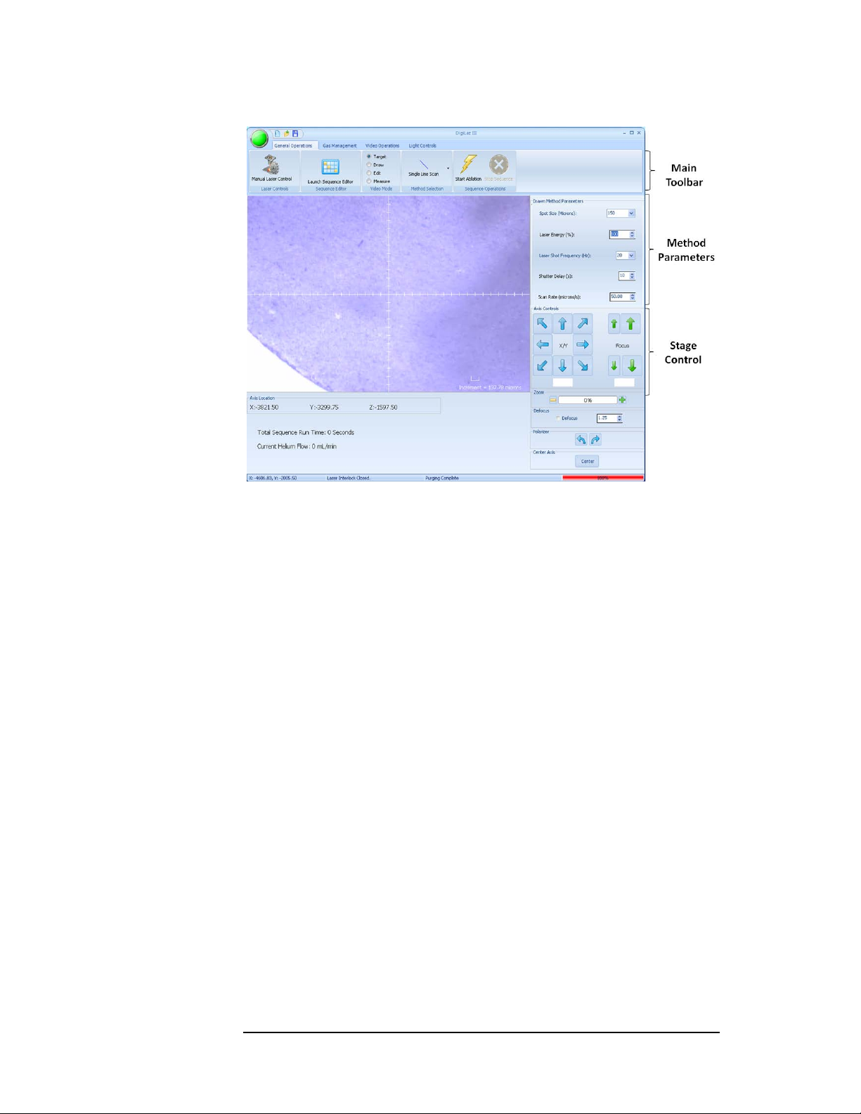
The sample image is viewed directly in the DigiLaz III software. The interface
achieves superior optical viewing of the digital image created by the sample
(see Figure 1-2).
Since air is unavoidably admitted into the sampling cell when changing
samples, removing the air from the carrier gas flow path prior to switching
back to the ICP-MS is required to prevent plasma collapse. To purge the sample
cell and prevent plasma collapse, the LSX-213 is equipped with 3-way
electrically actuated valves to direct the carrier gas flow to either the ICP-MS,
to a purge position or to a bypass position.
The CCD camera microscope system provides a means of visual identification
of the sample areas of interest and also for laser focusing. A digital crosshair is
an integral part of the digital image and can be adjusted depending on the
visual aspect of the samples. This crosshair provides a targeting mechanism
for the sample positioning at the point of laser impact.
CETAC LSX-213 Operator’s Manual
Chapter 1: Introduction
10
Figure 1-2 Sample Viewing Within the DigiLaz III software
Laser Head and Optics
The laser head is located in the upper chamber of the laser module. It is a
compact, rigid and stable-structured unit with a folded resonator geometry.
The opto-mechanical design of the Compact Folded Resonator (CFR) has
evolved over many generations of iterative refinements based on usage and
experience.
All of the optical elements are kept in precise relative alignment through
precision mounting techniques onto a single, stable optical table which is both
thermally and mechanically isolated from the rest of the system to minimize
any environmental influence on the laser or optics. The laser system used for
the LSX-213 system uses a liquid chiller which maintains a constant
temperature on the optical plate whether the unit is running at 100% or idle.
This results in unsurpassed laser stability and reliability.
Laser Characteristics
Frequency quintupled, Q-switched Nd:YAG laser, 213 nm
Spot size range: 10–200 µm (apertured)
>4mJ/pulse laser energy, 1% RSD, 1% RMS, computer controlled
Laser output energy is adjustable from 0–100%
Flat-top laser beam energy profile
Laser pulse width: < 6 nsec
Q-switch controlled laser frequency selection 1–20 Hz

CETAC LSX-213 Operator’s Manual
Chapter 1: Introduction
11
Viewing Optics and Video System
High intensity reflected and/or transmitted light illumination
Computer controlled focusing
5X, 40 mm focal length UV achromatic lens
Computer controlled polarizers for transmitted and reflected light
Thin-section holder for petrographic slides and other transparent samples
Real-time image acquisition at 1152 x 864 pixel resolution
Sampling System
Standard cell is 52 mm diameter by 52 mm high
Multiple cell types available to suit nearly any sample type
Quick release sample stage for easy sample exchange
Motorized X-Y-Z translation stage, 52 mm travel axis
0.25 µm step size, 0.05 µm resolution
3-stage motor drivers with manual override, auto-ramping up to 2 cm/sec
Adaptable volume, Teflon®and Viton™ construction
Automated valve system switches between cell purge, bypass, and online
modes
Ablation cell with removable quartz window for easy cleaning or
replacement
Computer Hardware and Software
The DigiLaz™ III software controls all laser functions and runs on the same
computer which controls the ICP for maximum ease of use
Compatible with the Microsoft Windows XP, Windows 2000, Vista, and
Windows 7 operating systems
Communication via serial port or USB
On-screen display of safety interlocks and laser status including laser firing,
door open, coolant temperature and flow interlocks
Universal communication protocol for synchronization of ICP-MS and laser
system using contact closure
Built-in laser ablation methods including multi-spot analysis, line scans and
raster, segmented line scanning, area scan and raster and advanced depth
profiling
Method/sequence saving, export and loading with sample image capture
and export. Method file management and text (*.txt) file management
access
Spot size and feature measurement functions
Single shot or automated repetition (burst or continuous mode)
Computer adjustable spot size using aperture focusing of the laser beam

CETAC LSX-213 Operator’s Manual
Chapter 1: Introduction
12
Automated video zoom and sample motion control
System Characteristics
Dimensions: Laser Module 69 x 46 x 51 cm
Weight: approximately 57 kg (125 pounds)
Power supply:20 x 30 x 37 cm
Power requirement: 100-250 VAC +/- 10%
Class 1 enclosure with safety interlocks
Independent programmable laser power supply module
Closed loop water cooling system with integrated DI cartridge
Options
GeoPro™ data handling software for geological analysis and transient data
collection
Custom designed sampling cells, oversize cell, document cell, core cell,
small sample cell. Inquire about custom designs
Laser and High Voltage Safety Features
The LSX-213 system has built in safety interlocks to disable the laser in the
event the cover is opened or the front door is opened during operation.
Another interlock on the laser power supply deactivates the laser if its
cover is opened during operation.
The laser power supply is controlled by a key switch and the key can be
removed only when the switch is in the OFF position to prevent unintended
operation.
Laser Ablation System Components
The LSX-213 Laser Ablation System is composed of the following components.
LSX-213 Module. The laser module contains the laser itself, all optics,
apertures, lighing etc. The sample cell on the translation stage is accessible
through the door and is pulled forward for easy access to the sample cell.
Power Supply. The LSX-213 power supply and integrated laser head
cooling unit contains all electronics for interfacing with the LSX-213 system
and safety interlocks for the laser head.
Host Computer. The control computer, whether integrated into the ICP
computer or a stand alone laser specific computer, executes the LSX-213
DigiLaz III software. The user-programmable software issues commands
that control LSX-213 functions, such as X-Y-Z sample positioning, laser
firing mode, laser power, CCD camera digital zoom, sample cell illumination
level, and sample cell purge/ICP argon flow control. System safety and laser
firing status are also monitored and displayed.
Host Computer Monitor. The real-time sample image and software
controls are displayed on the monitor.

CETAC LSX-213 Operator’s Manual
Chapter 1: Introduction
13
NOTE:
Please contact CETAC Technologies (800-369-2822, 402-733-2829) if you need
additional accessories not listed, need added features to integrate the LSX-213
Laser Ablation system into your analytical system, or have unique
requirements. Research and development of new features and accessories for
the LSX-213 Laser Ablation System are inspired by customer requests, and
responding to such requests is a continuing activity of CETAC Technologies.
Who Should Use This Product—Operator
Qualifications
The laser ablation system, along with this book, is intended for use analytical
chemists and lab technicians. To use this product safely and effectively, at least
a beginning level of knowledge and experience about laser safety, electrical/
electronic equipment operation and maintenance, personal computers and
ICP-MS or ICP-OES are required.
CHEMICAL INJURY HAZARD
The autosampler is intended for use only by qualified operators who have
been trained in safe laboratory practices. Make sure you know the hazards
associated with all of the chemicals you are using, and take the appropriate
precautions. Exposure to laboratory chemicals may result in serious injury.
Where to Go for More Information
New versions of this manual may be available under “Service and Support” on
CETAC’s Web site:
www.cetac.com
In addition to theLSX-213 Laser Ablation System Operator’s Manual, you can
refer to the following resources for citation material or for further information:
“Safe Use of Lasers" (Z136.1)
American National Standards Institute (ANSI)
11th West 42nd Street
New York, NY 10036
Phone: (212) 642-4900
www.ANSI.org
"A Guide for Control of Laser Hazards" (Publication 0165)
American Conference of Governmental and Industrial Hygienists (ACGIH)
6500 Glenway Avenue, Bldg. D-7
Cincinnati, OH 45211
Phone: (513) 661-7881
www.ACGIH.org
Occupational Safety and Health Administration (OSHA)
WARNING

CETAC LSX-213 Operator’s Manual
Chapter 1: Introduction
14
U.S. Department of Labor
200 Constitution Avenue NW
Washington, DC 20210
Phone: (202) 523-8148
www.OSHA.gov
"Performance Standards for Laser Products"
United States Code of Federal Regulations
21 CFR 1040.10(d) and 1040.11.
The CETAC LSX-213 Laser Ablation System Service Manual.
CETAC Technologies Customer Service and Support:
Phone: 1 (800) 369-2822 (USA only)
1 (402) 733-2829
Fax: 1 (402) 733-1932
E-mail: custserv@cetac.com
Preparing for Installation
Ventilation
Allow at least 5 cm clearance on all sides of the instrument for ventilation.
Do not operate the instrument if the cooling fans are blocked or obstructed in any
manner.
CAUTION

15
2Using the LSX-213
Laser Ablation
System
The LSX-213 system is both reliable and easy to use. Before using the LSX-213
system, however, ensure that your lab environment provides operating
conditions that will prolong the life of the LSX-213 system. Once the proper
operating conditions are met, you can load samples and perform analysis with
the laser ablation system.
This chapter explains how to create the proper operating conditions for using
the LSX-213 system. It also explains laser safety precautions, how to prepare
and load the samples, start and shut down the laser ablation system, analysis
procedures and initial operating parameters.
Establishing Optimal Operating Conditions
The LSX-213 system operates reliably even under less than ideal conditions. It
is not, however, indestructible. Malfunction or damage can occur if specific
operating conditions are not met. Meeting these conditions requires that you
create the proper lab environment, replace laser ablation system components
that wear out under normal use and purchase the appropriate supplies for use
with the laser ablation system. The following sections explain how to meet
these conditions.
NOTE:
Damage or malfunction that results from unsatisfactory operating conditions
may constitute misuse and abuse and be excluded from warranty coverage.

CETAC LSX-213 Operator’s Manual
Chapter 2: Using the LSX-213 Laser Ablation System
16
Creating the Lab Environment
To create satisfactory operating conditions in your lab environment, follow
these guidelines:
Operate the LSX-213 system in a conventional lab environment where the
temperature is 50–85 °F (10–30 °C); the humidity is 20–70%
non-condensing; and the unit is not exposed to excessive flammable or
corrosive materials.
Avoid rough handling of the LSX-213 system. Do not expose the laser
ablation system to vibration or shock.
Protect the LSX-213 system from long-term exposure to condensation,
corrosive materials, solvent vapor, standing liquids, liquid spills into the
electrical equipment or operation inside an acid hood or glove box.
Exposures of this type can degrade the optics, corrode and damage
mechanical drive mechanisms, as well as the electronics.
Observe the same general electrostatic discharge precautions as with any
other integrated circuit electronic devices. Low humidity environments,
especially when combined with static-generating materials, require
maximum care.
Discharge static buildup and ground to the laser ablation system base or LSX-213
system cabinet before performing any maintenance. Do not touch or short-circuit
bare contacts of any communications ports.
Avoid exposing the LSX-213 system to high levels of electromagnetic or
radio frequency interference (EMI/RFI), or radioactivity. EMI/RFI can
cause erratic operation, high levels of radioactivity may cause electronic
component failure, and will prohibit factory repair if so contaminated.
Contact CETAC Technologies for assistance if the LSX-213 system will be
required to operate in a hostile environment.
CAUTION

CETAC LSX-213 Operator’s Manual
Chapter 2: Using the LSX-213 Laser Ablation System
17
Replacing Laser Ablation System Components
The following LSX-213 system components wear out, or become contaminated
under normal use, and must be replaced periodically.
System Tubing
Chiller water
Laser flashlamp
Chiller de-ionizer
If you fail to replace these components when they deteriorate, the laser
ablation system will not function properly.
Purchasing Supplies
Because the usage rate of consumable materials and the life span of
expendable components will vary, you should maintain an adequate supply of
spares. When you need to purchase additional supplies, it is important that
you choose the appropriate components and materials. A one-year
consumables kit is available from CETAC.
When you purchase replacement parts or consumable supplies, make sure
they meet the following requirements:
Use only distilled water (not 18MΩ laboratory water, bottled distilled water
works best) when changing coolant. Tap water or any other coolant will
leave deposits in the cooling system, may damage the cooling unit or laser
head, or cause other malfunctions.
Do not attempt to use a substitute laser flashlamp; otherwise, leakage and
laser head damage will result. Service only with an exact replacement.
Only a factory trained service engineer should do laser flashlamp replacement.
Contact CETAC Technologies at 800-369-2822 or 402-733-2829 for more
information, or a certified laser system technician.
Use of unsuitable coolants, consumable supplies or inferior replacement
parts may result in laser ablation system malfunctions, ICP malfunctions,
invalid analysis results or hazardous conditions. Be sure all replacements
meet the specified requirements.
To order additional supplies, contact the CETAC Technologies Customer
Service department.
CAUTION
WARNING
CETAC LSX-213 Operator’s Manual
Chapter 2: Using the LSX-213 Laser Ablation System
18
Connecting the Laser Ablation System
Two people are required to lift the unit. Lifting should be done with a
person situated on either side of the instrument.
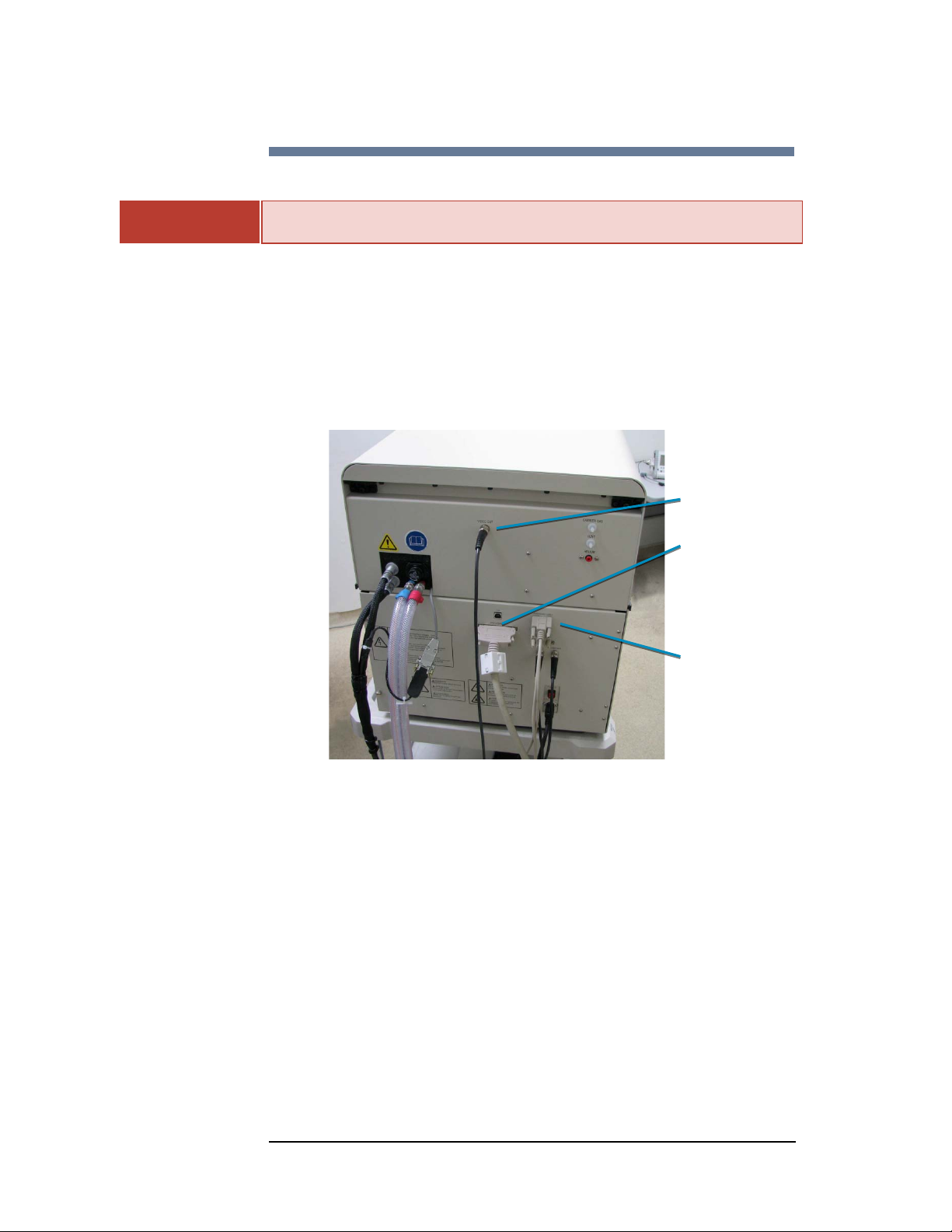
Connections to the Host Computer
Assuming that the LSX-213 has been installed by a qualified CETAC
representative, the electronic connections from the host computer to the LSX-
213 should already be in place. These include the 52-pin control cable, the
RS232 cable to COM 1 (or USB if desired) and the BNC coaxial video cable from
the video card on the computer to the video out port on the back of the LSX. If
the system is being self-installed, contact your CETAC representative for
detailed installation instructions.
Figure 2-1 Connections to Host Computer
WARNING
Video Out
(to Converter)
52-Pin Control Cable
RS232 Serial Data

CETAC LSX-213 Operator’s Manual
Chapter 2: Using the LSX-213 Laser Ablation System
19
Figure 2-2 Host Computer
Connections to the Power Supply/Cooler
Likewise, all connections between the Laser and the power supply should be in
place including the water lines, the primary power cable connecting the power
supply and laser, the RS232 cable from the power supply to the laser, the BNC
coaxial connecting the “remote link” connector on the power supply to the
“Laser Safe” connector on the laser and another BNC cable connecting the “Q-
switch sync” on the power supply to “Q-switch” on the laser.
Figure 2-3 Connections to Power Supply/Cooler
Laser Power from
Power Supply
Serial Connection from
Power Supply
Electronics Power
from Power Supply
Q-Switch and
Laser Safe from
Power Supply
Coolant from
Power Supply
USB-Mouse and Keyboard
52-Pin Control Cable
RS232 Serial Data
USB-Video to PC
USB-
Video to PC
Video from LSX-213

CETAC LSX-213 Operator’s Manual
Chapter 2: Using the LSX-213 Laser Ablation System
20
Figure 2-4 Power Supply/Cooler
Gas Connections
The LSX-213 uses both argon and helium during operation. The argon source
is from the nebulizer gas from the host ICP. Using the tubing and fittings
supplied to connect the nebulizer gas out port on the ICP to the “Argon” port on
the back of the LSX-213. For the helium connection, use the supplied fittings to
connect 1/8” tubing from the source to the push fitting on the rear of the laser.
The vent port may be left open to atmosphere unless very hazardous material
is being used which would require complete containment of residual sample
material.
Figure 2-5 Gas Connections
Using the Laser Ablation System
Front Panel Indicators
Status Indicator: LED located on upper front left of the LSX-213 system.
Informs the operator of the current instrument conditions as follows:
Argon In
(Nebulizer Gas)
Argon Out
(To Analytical
Instrument)
Helium In
Coolant Out
Coolant In
Laser Power, Electronics
Power, and Serial Connection
Table of contents
Other CETAC Laboratory Equipment manuals

CETAC
CETAC ASXpress User manual

CETAC
CETAC ASX-260 User manual

CETAC
CETAC ASXPRESS PLUS User manual

CETAC
CETAC ASX-520 Use and care manual

CETAC
CETAC ASX-520 User manual

CETAC
CETAC ASX-500 Series User manual

CETAC
CETAC ASX-510 Guide

CETAC
CETAC ASX-1400 User manual

CETAC
CETAC ASX-520 Instruction Manual

CETAC
CETAC ASXPRESS PLUS User manual

Popular Laboratory Equipment manuals by other brands


Keysight
Keysight N777-C Series user guide

ThermoFisher Scientific
ThermoFisher Scientific invitrogen Countess 3 user guide

Edvotek
Edvotek Mezzo 533 manual

Stag
Stag AC W03 user manual

Thermo Scientific
Thermo Scientific Dionex IonPac AS31 product manual

VistaLab
VistaLab Ovation 9060-1011 Replacement instructions