CETAC ASX-520 User manual

Complete Guide for Upgrading ASX-520
and ASX-520HS Autosamplers with an
EXR-8

Installing the Extended Rack
The EXR-8 Extended Rack is designed for easy installation. Installation consists of four parts:
Upgrading the firmware on the CETAC autosampler, removing the autosampler head from its
base, assembling the Extended Rack, and connecting it to the host analytical instrument.
This document contains three guides to help in the installation of the EXR-8:
Guide for Upgrading the Firmware on the ASX-520 and ASX-520HS Autosamplers with an
EXR-8
1. Software and Firmware Upgrade
2. Accessing the Board inside the Autosampler
3. Establish Communications
4. Setup of Rabbit Utility
5. Autosampler Programming Configuration
6. Autosampler Normal Configuration
7. Verification of Firmware Upgrade
Guide to Operating a CETAC Autosampler Using HyperTerminal
1. Steps for operating the autosampler with HyperTerminal
Guide to Installing the EXR-8 with a CETAC Autosampler
1. Assemble the Cart.
2. Remove the head assembly from the base of the autosampler.
3. Mount the head assembly (autosampler) onto the Extended Rack.
4. Connect the autosampler to the Host Computer
5. Align the Extended Rack.

Guide for Upgrading the Firmware
on the ASX-520 and ASX-520HS
Autosamplers with an EXR-8
Guide for Upgrading the Firmware on the ASX-520 and ASX-520HS Autosamplers with an EXR-8
2
This guide describes the necessary steps for upgrading the firmware on the ASX-520 and
ASX-520HS autosamplers.
Software and Firmware Upgrade
The software needed to upgrade the firmware on the autosampler and the firmware upgrade file
are both included on the CD provided with the EXR-8. The software and firmware can also be
downloaded from the CETAC web site. To download the software and the latest firmware, go to
http://www.cetac.com/downloads/download.html and select Autosampler Firmware Update. You
will be presented with a form that asks for basic contact information. Upon completion, you will
be e-mailed a web site address, a login ID and a password that will allow you to download any
new firmware upgrade that may be available for your autosampler along with the necessary
software to perform the upgrade.
Accessing the Board inside the Autosampler
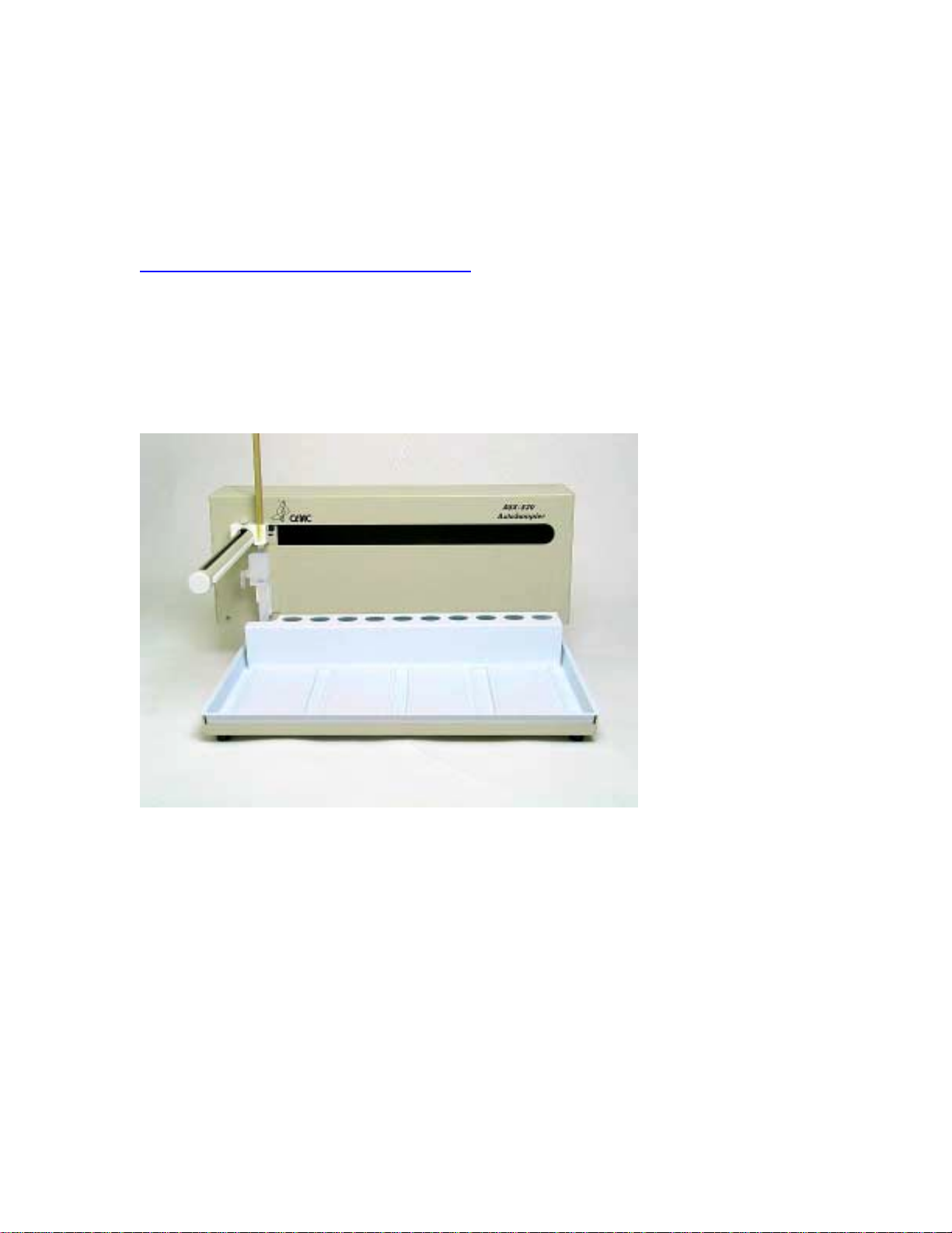
1. Place the autosampler on a flat surface (Figure 1-1) and turn the unit off.
Figure 1-1. Front view of ASX-520 Autosampler.
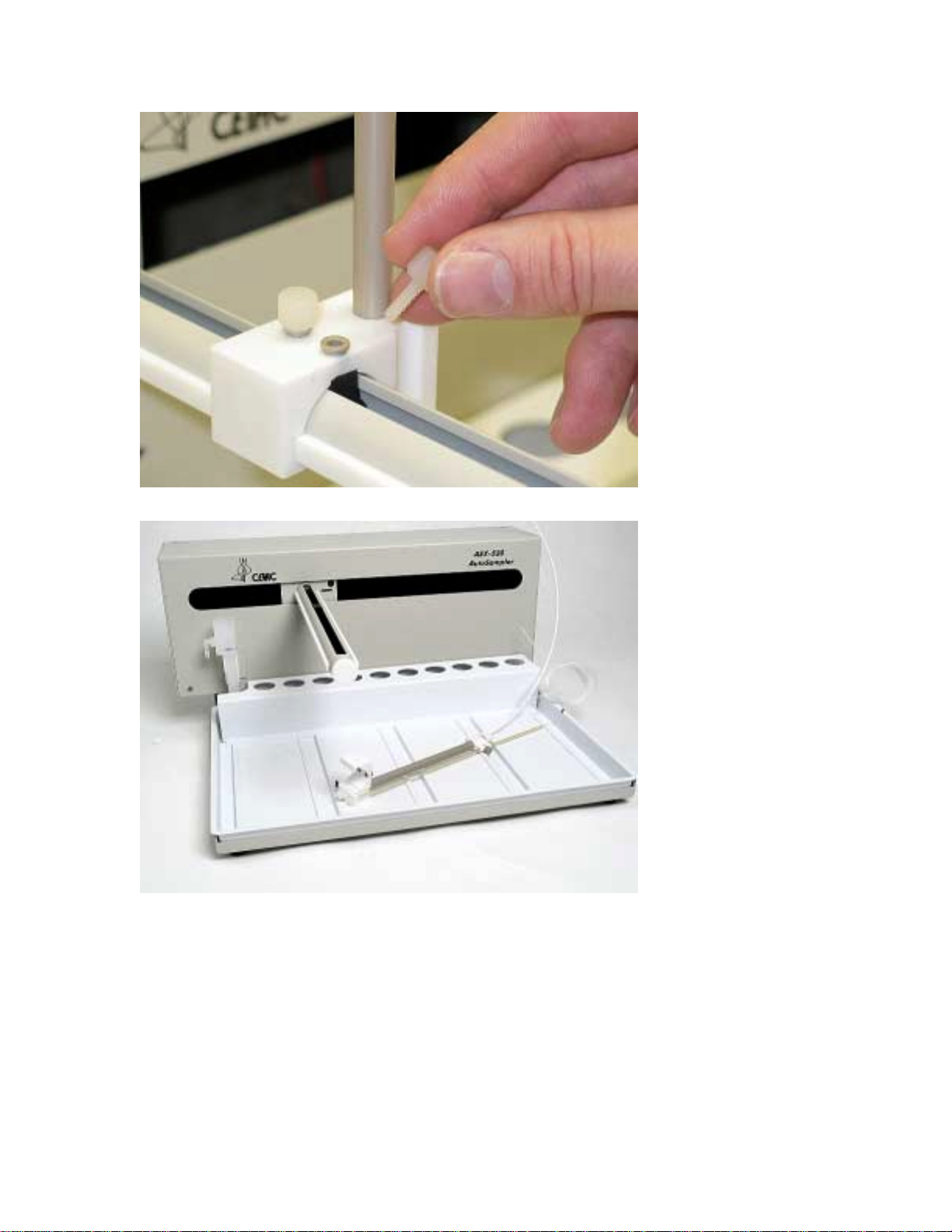
2. Remove the two Kynar thumbscrews from the Y-axis home block (Figure 1-2).
Guide for Upgrading the Firmware on the ASX-520 and ASX-520HS Autosamplers with an EXR-8
3
Figure 1-2. View of Y- axis home block with Kynar thumbscrews.
Figure 1-3. Z-drive removed from arm assembly.
3. Remove the whole Z-drive assembly from the arm by pulling the whole Z-drive assembly
forward and off the autosampler arm (Figure 1-3).
Guide for Upgrading the Firmware on the ASX-520 and ASX-520HS Autosamplers with an EXR-8
4
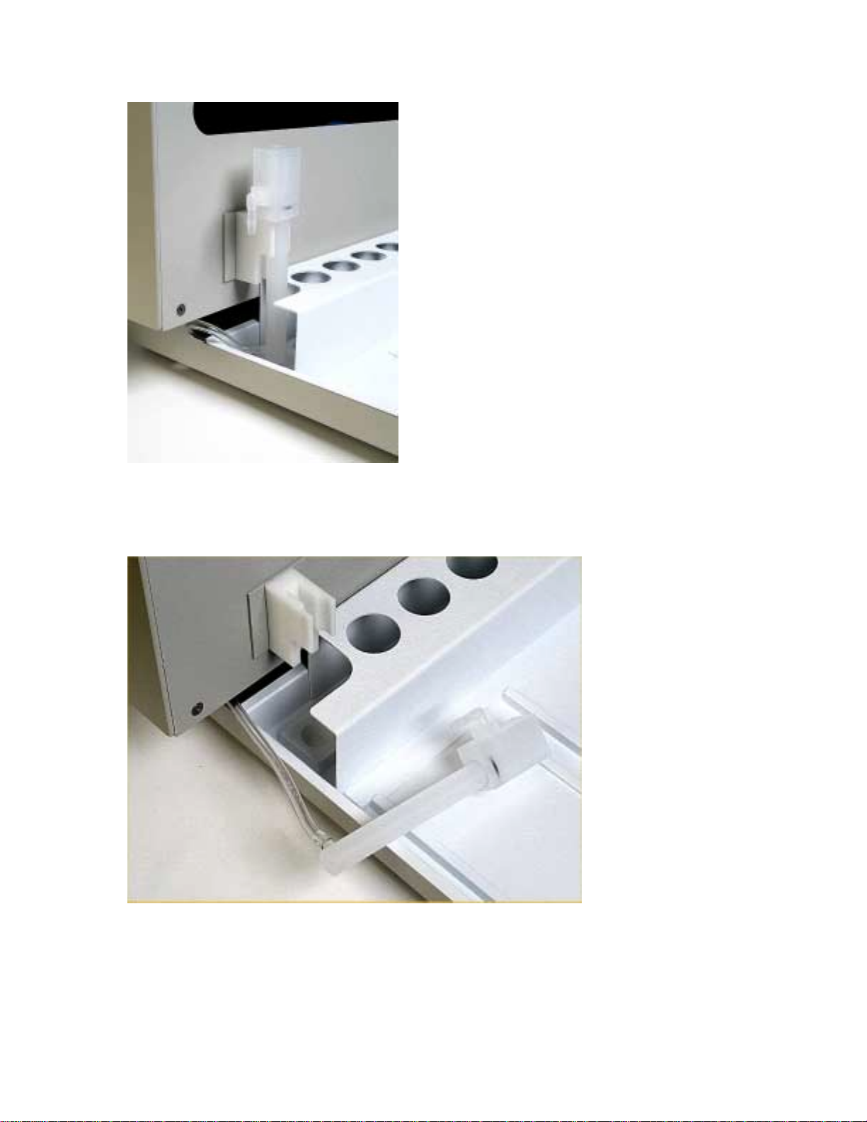
Figure 1-4. View of rinse station.
4. Once the Z-drive assembly is removed, remove the rinse station (Figure 1-4). Turn the rinse
station ¼ turn counter-clockwise while pulling up. Also, the tubing located at the bottom of
rinse station will have to be removed or moved aside (Figure 1-5).
Figure 1-5. View of rinse station removed from the front cover.
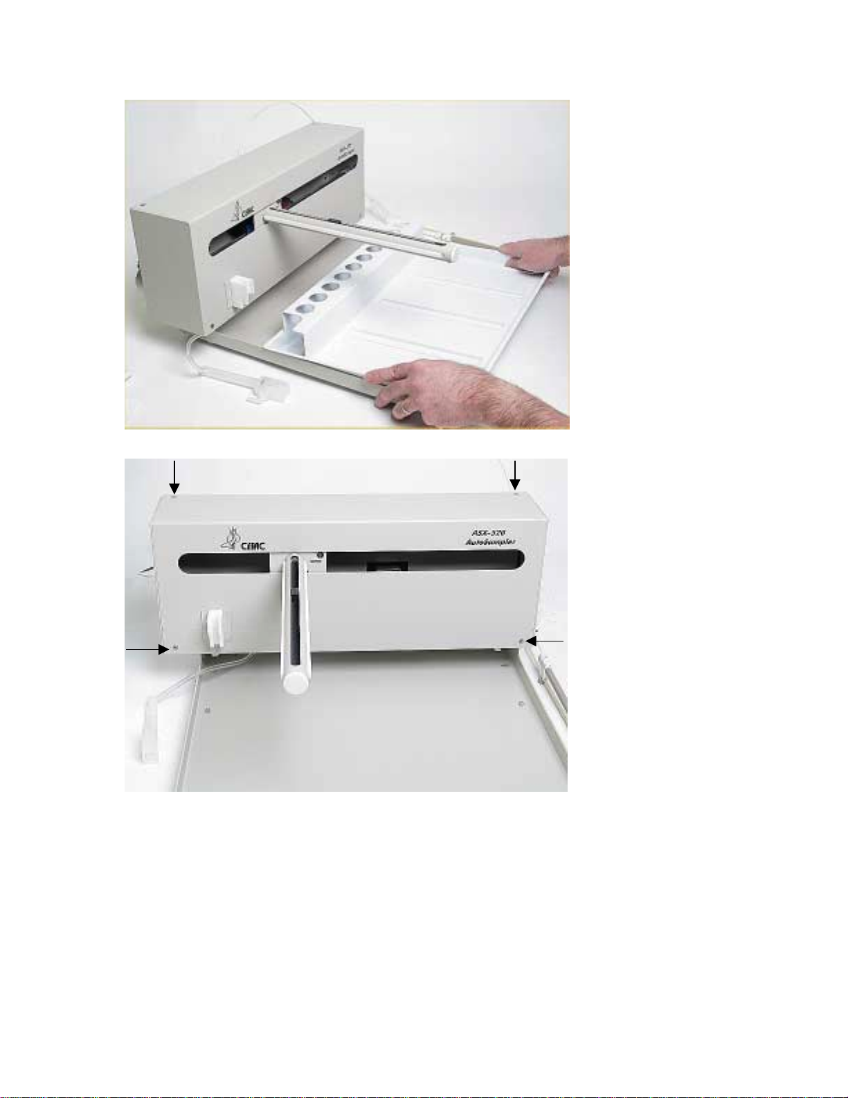
5. The autosampler tray should then be removed. Lift up the tray and pull out (Figure 1-6).
Guide for Upgrading the Firmware on the ASX-520 and ASX-520HS Autosamplers with an EXR-8
5
Figure 1-6. Removing the tray.
Figure 1-7. Front view of ASX-520 Autosampler showing front cover screws.
6. Next, the front cover needs to be removed. Remove the four corner screws (Figure 1-7).
7. The front cover can be removed by lifting it slightly and pulling forward (Figure 1-8).

Guide for Upgrading the Firmware on the ASX-520 and ASX-520HS Autosamplers with an EXR-8
6
Figure 1-8. View of ASX-520 Autosampler with the front cover being removed.
Figure 1-9. View of inner shield inside the ASX-520 Autosampler.
8. The five screws that hold the inner shield will have to be removed. Move the Y-axis
assembly all the way to the left (Figure 1-9).
9. The inner shield can be removed by lifting it up while pulling forward (Figure 1-10).

Guide for Upgrading the Firmware on the ASX-520 and ASX-520HS Autosamplers with an EXR-8
7
Figure 1-10. Removal of inner shield.
Figure 1-11. View of ASX-520 with inner shield removed.
Establish Communications
1. Put the Z-drive assembly back on the arm and screw in the Y-axis home block.
2. Reconnect the power cord and the serial cable and turn the autosampler on.
3. Start HyperTerminal. (For instructions on using HyperTerminal, refer to the Guide to
Operating a CETAC Autosampler using HyperTerminal).
4. In HyperTerminal type VERSS. The system will respond with the current firmware version
and it should be noted.
5. In HyperTerminal type HOME. This is to verify that the system is communicating.

Guide for Upgrading the Firmware on the ASX-520 and ASX-520HS Autosamplers with an EXR-8
8
Figure 1-12. Rabbit Field Utility Appliacation
Setup of Rabbit Utility
1. Run the Rabbit Field Utility application, RFU.exe. (Figure 1-12).
2. Select the menu Setup, and then Communications.
3. On the Communications Options window (Figure 1-13), in the Comm Port field, select the
COM port on the computer that is connected to the autosampler. Press the OK button.
Figure 1-13. Communications Options Window.
4. Select the menu Setup, and then File Locations.
Guide for Upgrading the Firmware on the ASX-520 and ASX-520HS Autosamplers with an EXR-8
9
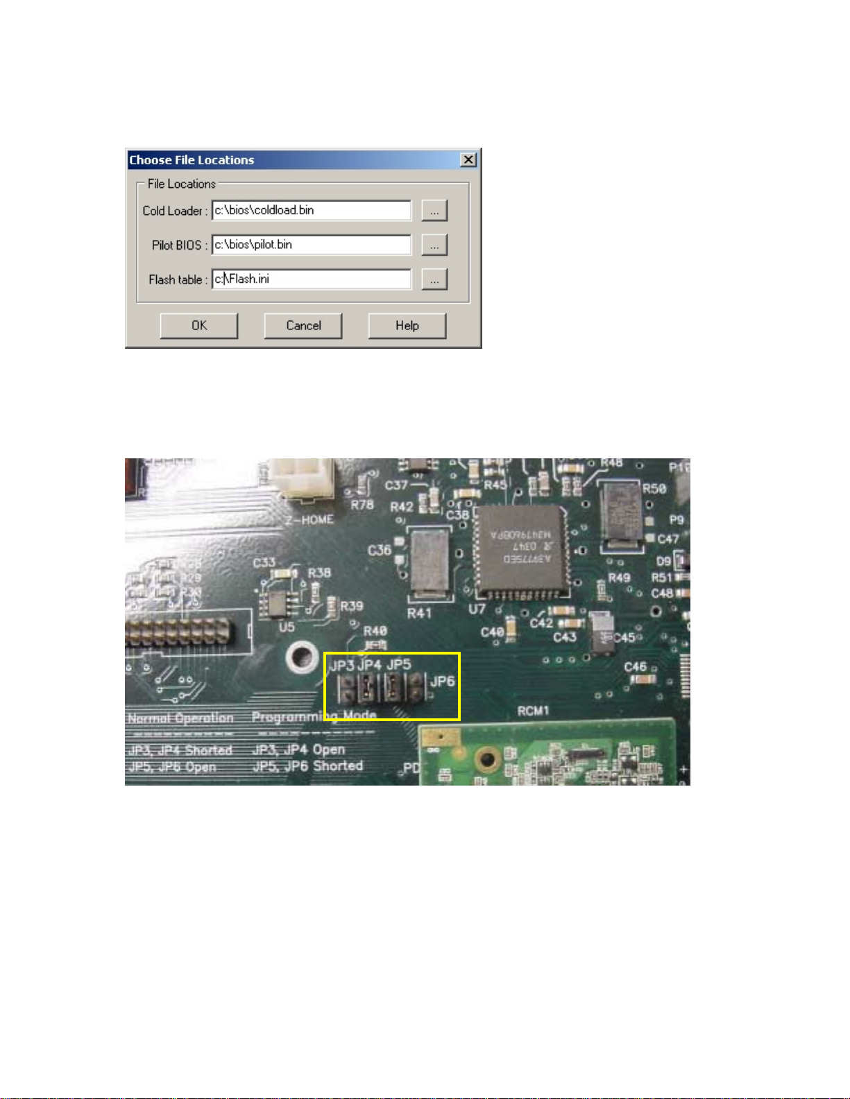
5. On the Choose File Locations window (Figure 1-14), fill in the fields with Cold Loader as
coldload.bin and Pilot BIOS as pilot.bin. Press the OK button
Figure 1-14. Choose File Locations Window.
Autosampler Programming Configuration
1. Turn off the autosampler.
2. On the board move the jumper from J3 to J5 (Figure 1-15).
Figure 1-15. Jumpers on board.
3. Turn the autosampler back on.
Upgrading the Firmware
1. In the Rabbit Field Utility, select the menu File, and then Load Flash Image.
2. On the Choose Flash Image window (Figure 1-16), select the firmware file.

Guide for Upgrading the Firmware on the ASX-520 and ASX-520HS Autosamplers with an EXR-8
10
Figure 1-16. Choose Flash Image Window.
3. Select the OK button. A progress bar will appear.
4. When it is complete, the Rabbit Field Utility can be closed.
Autosampler Normal Configuration
1. Turn off the autosampler.
2. On the board move the jumper from J5 back to J3 (Figure 1-15).
3. Turn the autosampler back on. The autosampler should go to the home position.
Verification of Firmware Upgrade
1. Start HyperTerminal. (For instructions on using HyperTerminal, refer to the Guide to
Operating a CETAC Autosampler using HyperTerminal).
2. In HyperTerminal type VERSS. The system should respond with the new firmware version.
3. In HyperTerminal type SETTYPE=nnn where nnn is the configuration number.
Configuration
Number Configuration Type
23 CETAC Standard
24 CETAC Standard, High Speed
25 PE
26 PE High Speed

Guide to Operating a CETAC
Autosampler Using HyperTerminal

Guide to Operating A CETAC Autosampler Using Hyper Terminal
2
All CETAC autosamplers can be controlled using a serial communications protocol. This
guide explains how to operate any one of the CETAC autosamplers using the Windows
HyperTerminal program.
Steps for operating the autosampler with HyperTerminal
1. Using a serial cable, connect the CETAC autosampler with the computer. Plug each end of
the serial cable into the COM 1 port of the autosampler and the computer, respectively.
2. Turn on the computer (must have Windows operating system) and select the Accessories
folder. Select the HyperTerminal folder and then the HyperTerminal program.
3. A window will appear as in Figure 1-1. Enter COM 1 in the name box. Press the OK button.
4. In the Connect To window (Figure 1-2), in the field Connect using, select COM1. Press the
OK button.
Figure 1-1
Figure 1-2

Guide to Operating A CETAC Autosampler Using Hyper Terminal
3
5. The COM1 Properties window will appear (Figure 1-3). Set the fields as follows: Bits per
second to 9600 and Flow control to None. Then press the OK button.
6. The HyperTerminal window will then open (Figure 1-4).
Figure 1-4
Guide to Operating A CETAC Autosampler Using Hyper Terminal
4
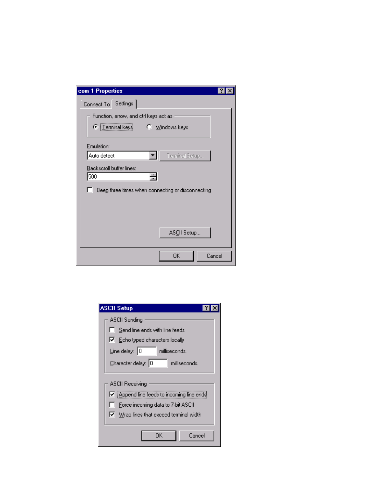
7. Select File. Then select Properties.
8. When Properties window appears (Figure 1-5), select the Settings tab.
9. Press the ASCll Setup… button. A window for ASCll Setup will appear (Figure 1-6). You will
need to check Echo typed characters locally and Append line feeds to incoming line ends as
shown in Figure 1-6. Press the OK button.
Figure 1-5
Figure 1-6

Guide to Operating A CETAC Autosampler Using Hyper Terminal
5
10. Turn on the autosampler and the HyperTerminal window (Figure 1-7) should display an OK.
11. The following commands will produce various responses of the autosampler.
a) Ver (returns firmware version)
b) Home ( returns all axis to home position, same as power up)
c) Tray=n (defines tray size and n= #of positions)
d) Tube=3-4-150 (tube=row-colimn-down as defined by tray command)
e) Pmp on ( pump on if unit has a pump)
f) Pmp off (pump off if unit has a pump)
g) Rinse (moves sipper to the rinse position, extends and retracts the sipper 3 times and
starts rinse pump. Stays in down position with pump running. up,pmp off stops the pump
h) Down=n (moves the z-axis down by the parameter(n) in mm.(do not run down command
if sipper is not all the way up on up position or damage may occur to sipper or z-axis)
i) Up (moves z-axis to upper most postion.)
With the commands listed in Step 11 it can be determined if the CETAC autosampler is
communicating and functioning properly. If more assistance is needed, please contact customer
service.
Figure 1-7

Guide to Installing the EXR-8 with a
CETAC Autosampler
Guide to Installing the EXR-8 with a CETAC Autosampler
2
Assembling the Cart
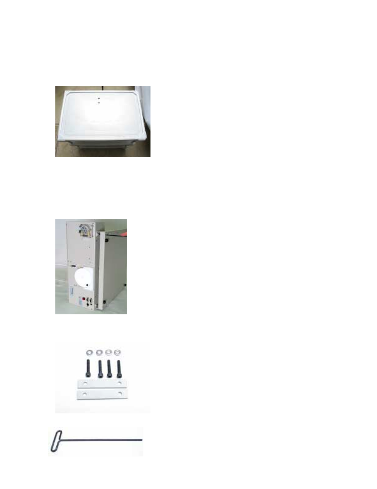
The Cart should be assembled using the instructions provided with the Cart. The Cart should
have two holes on the top layer (Figure 1).
Figure 1. Cart from above.
Removing the head assembly from the base of the autosampler
1. Unplug the autosampler.
2. Remove all sample vials and the tray.
Figure 2. Autosampler on its side
3. Place the autosampler on its side (Figure 2).
4. Remove the contents from Bag A and locate the hex wrench (Figures 3 and 4).
Figure 3. Contents of Bag A.

Guide to Installing the EXR-8 with a CETAC Autosampler
3
Figure 4. Hex wrench.
5. Using the hex wrench, remove the four screws connecting the head assembly to the base
(Figure 2).
6. Remove the head assembly from the base.
Mounting the head assembly (autosampler) onto the Extended Rack
1. Place Extended Rack onto the Cart such that the center holes of the Extended Rack are
aligned with those on the Cart.
2. Place the standards rack on the rail plate (Figure 5).
Figure 5. Standards rack placed onto the Extended Rack.
3. While holding the standards rack, place the head assembly on the standards rack (Figure 6).
Figure 6. Head assembly placed onto the standards rack.
4. Using the contents of Bag A (Figure 3), place the washers on the screws.
5. Attach the left side of the head assembly to the Extended Rack using the hex wrench as
shown in Figures 7 and 8.
Figure 7. Attaching the head assembly (first screw).
Other manuals for ASX-520
2
This manual suits for next models
1
Table of contents
Other CETAC Laboratory Equipment manuals

CETAC
CETAC ASX-510 Guide

CETAC
CETAC ASX-1400 User manual

CETAC
CETAC LSX-213 User manual

CETAC
CETAC ASX-520 Instruction Manual

CETAC
CETAC ASX-260 User manual

CETAC
CETAC ASXpress User manual

CETAC
CETAC ASXPRESS PLUS User manual

CETAC
CETAC ASX-500 Series User manual

CETAC
CETAC ASX-520 Use and care manual

CETAC
CETAC ASXPRESS PLUS User manual


