CETAC ASXPRESS PLUS User manual

CETAC
ASXPRESS
®
PLUS
Rapid Sample Introduction System
Manual Part Number 480167Rev 6
Operator’s Manual

COPYRIGHT
© 2009-2011 CETAC Technologies
480167 Rev 6 , October, 2011
CETAC Technologies authorizes its customers
to reproduce, transmit, or store this document
in its entirety, including this page, for the
express purpose of installing, operating, or
maintaining the product described herein.
CETAC Technologies
Customer Service & Support
14306 Industrial Road
Omaha, Nebraska 68144, USA
Phone (800) 369-2822 (USA only)
Phone (402) 733-2829
Fax (402) 733-1932
E-mail [email protected]
REVISIONS
CETAC Technologies strives to provide the
scientific community with an unparalleled
combination of effective technology and
continuing value. Modular upgrades for
existing instruments will continue to be a
prime consideration as designs progress.
CETAC Technologies reserves the right to
revise this document and/or improve
products described herein at any time without
notice or obligation.
TRADEMARK ACKNOWLEDGEMENTS
Windows is a registered trademark of
Microsoft Corporation in the United States and
other countries.
iTEVA is a trademark of Thermo Fisher
Scientific Inc.
WinLab32 is a trademark of PerkinElmer
Instruments LLC.
ICP-MS Expert is a trademark of Bruker
Corporation.
ChemStation is a trademark of Agilent
Technologies.
PharMed and Tygon are registered
trademarks of Saint-Gobain Performance
Plastics.
DuPont™, Kapton®, Tefzel® and Viton® are
trademarks or registered trademarks of E.I. du
Pont de Nemours and Company.
All other marks are the property of their
respective owners.

3
Contents
1Introduction ........................................................................................................... 7
Overview....................................................................................................................................7
About This Book..................................................................................................................... 9
Who Should Read This Book......................................................................................... 9
Supported Autosamplers................................................................................................ 9
Updates .................................................................................................................................. 9
Rapid Sample Introduction System Standard Components ............................... 9
Optional Accessories/Components .............................................................................13
Additional Equipment Required...................................................................................13
Where to Go for More Information..............................................................................14
Installation Overview.........................................................................................................14
2Preparing for Installation............................................................................... 15
Choosing a Location............................................................................................................15
Space Requirements.......................................................................................................16
Liquid Waste Routing Requirements......................................................................16
Power Requirements......................................................................................................16
Unpacking the ASXPRESS PLUS Rapid Sample Introduction System ................17
3Preparing an ASX-500/510 Autosampler.................................................. 19
Upgrade the Firmware......................................................................................................20
Checking the Firmware Version................................................................................20
Upgrading the EPROM..................................................................................................20
Install the Xpress Rinse Station and Rinse Tubing ...............................................21
Removing the Existing Rinse Station......................................................................21
Installing the Xpress Rinse Station..........................................................................21
Install the External Rinse Pump....................................................................................22
Install the 1.0mm ID Sample Probe on the Autosampler...................................24
4Preparing an ASX-260 or ASX-520 Autosampler..................................... 25
Identifying the Peristaltic Pump...............................................................................25
Rinse Pump Configurations ........................................................................................26
Other Setup Tasks ...........................................................................................................26
Installing the Xpress Rinse Station ..............................................................................27
Removing the Existing Rinse Station......................................................................27
Installing the Xpress Rinse Station..........................................................................27
Installing the Gravity Drain with Built-in Pump....................................................28
Notes .....................................................................................................................................29
Installing the Gravity Drain with External Pump..................................................30
Notes .....................................................................................................................................30
Installing a Pumped-Drain Rinse Arrangement with Both Pumps................31
Notes .....................................................................................................................................32
Installing the 1.0mm ID Sample Probe.......................................................................34

ASXPRESS PLUS Rapid Sample Introduction System Operator’s Manual
Contents
4
Accessing the Interior of the Autosampler ..............................................................34
Setting the Pump Speed Jumper (ASX-520/ASX-520HS/EXR-8) .....................42
Upgrading the Firmware..................................................................................................42
Supported Firmware Versions...................................................................................43
Where to Get the Firmware ........................................................................................43
Autosampler Programming Configuration .........................................................43
Loading the Firmware Upgrade ...............................................................................45
Upgrading (loading) the Firmware ........................................................................48
Returning the Autosampler to Normal (Non-Programming Mode)
Configuration...........................................................................................................50
Verification of Firmware Upgrade ..........................................................................51
Closing Up the Autosampler...........................................................................................51
5Preparing an ASX-1400/1600 Autosampler............................................. 53
Install the Xpress Rinse Station and Modified Rinse Tubing Arrangement
............................................................................................................................................55
Connecting the Rinse Tubing .........................................................................................58
Rinse Connections Using the Existing Peristaltic Pump ....................................60
Installing the 1.0mm ID Sample Probe on the Autosampler............................61
Removing the Sample Probe.......................................................................................62
Removing the Stirrer Assembly.................................................................................63
Replacing the holder block..........................................................................................63
Reinstalling the Stirrer Assembly.............................................................................64
Installing the Sample Probe .......................................................................................65
6Installing the Valve/Pump Module .............................................................. 67
Install the 6-Port Valve .....................................................................................................69
Install the Sample Loop ....................................................................................................70
Connect the Autosampler Probe to the Valve/Pump Module .........................71
Connect the Valve/Pump Module to the Nebulizer..............................................71
Optional: Installing an Internal Standard Addition Mixing Tee......................73
Optional: Installing a Passive Bubbling Tee ............................................................74
7Installing the Electronics Module................................................................. 77
Connecting the Electronics Module to the Power Supply .................................78
Connecting the Electronics Module to the Valve/Pump Module ...................79
Connecting the Electronics Module to the External Rinse Pump...................79
Connecting the Electronics Module to the Autosampler ...................................80
Connecting the Electronics Module to the Host Computer...............................80
Establishing an OEM COM Connection (RS-232) ..............................................81
Establishing an OEM COM Connection (USB).....................................................82
Establishing a GUI COM Connection (RS-232) ...................................................86
Establishing a GUI COM Connection (USB)..........................................................86
8Installing the Software..................................................................................... 87
Installing the Xpress Configuration Tool..................................................................87
Running the Xpress Configuration Tool for the First Time ..............................92
Inspecting the ASXPRESS PLUS System Components ..........................................92
Making sure the system is ready...............................................................................93
Setting the communication port ..............................................................................93
Verifying communication ............................................................................................93
Configuring the personality........................................................................................95
Performing some basic communication tests.....................................................96

ASXPRESS PLUS Rapid Sample Introduction System Operator’s Manual
Contents
5
Home the valve .................................................................................................................98
9Configuring the ASXPRESS PLUS System......................................................... 99
Timing Parameters .............................................................................................................99
Operation Controls...........................................................................................................101
Enable ASXpress Operation .....................................................................................101
Extra Loop Rinse...........................................................................................................101
Enable Vacuum/Autosampler Peri-Pump Timeout......................................101
Return Probe to Previous Sample .........................................................................101
Manual Controls ................................................................................................................101
Valve Control..................................................................................................................101
Vacuum Pump Control...............................................................................................101
Autosampler Pump Control .....................................................................................102
Manual Cycle ..................................................................................................................102
Manual Cycle at Rinse ................................................................................................102
Home AutoSampler .....................................................................................................102
Save Configuration to ASXpress+ ..........................................................................102
Saving Methods..................................................................................................................102
Additional Xpress Configuration Tool Features..................................................103
Built-In Help ...................................................................................................................103
Comm Port.......................................................................................................................103
Change Personality......................................................................................................103
Notes Window................................................................................................................103
Service Log ......................................................................................................................105
10 Using the Rapid Sample Introduction System........................................107
Establishing Optimal Operating Conditions .........................................................107
Creating the Lab Environment...............................................................................108
Replacing Rapid Sample Introduction System Components.....................108
Purchasing Supplies ....................................................................................................109
Starting the System..........................................................................................................110
Shutting Down the System ...........................................................................................111
Flushing the Rinse Station and Flow Path.............................................................112
Developing a Method ......................................................................................................113
11 Maintaining the ASXPRESS PLUS Rapid Sample Introduction System.115
Regular Inspection of ASXPRESS PLUS Components.............................................116
Cleaning the System ........................................................................................................117
Daily External Cleaning.............................................................................................117
Cleaning the Filters......................................................................................................117
Cleaning the 6-Port Valve.........................................................................................118
Checking for Leaks ...........................................................................................................120
Replacing the Tubing ......................................................................................................120
Replacing or Reorienting the 6-Port Valve............................................................121
Replacing the Battery......................................................................................................124
Updating Firmware..........................................................................................................126
12 Troubleshooting the Rapid Sample Introduction System ..................127
If the Valve/Pump Module Does Not Appear to be Operating......................127
If the 6-Port Valve Is In the Wrong Position (Re-Homing) ............................128
If Some Samples are Missed.........................................................................................128
If There are Data Quality Problems / QC Failure................................................128
Power System Problems................................................................................................129

ASXPRESS PLUS Rapid Sample Introduction System Operator’s Manual
Contents
6
Communications Interface Problems...................................................................... 130
RS-232 Cable Problems..............................................................................................130
USB cable Problems.....................................................................................................130
Software Configuration Problems ........................................................................131
Returning the Product to CETAC for Service .......................................................133
Shipping the Product ..................................................................................................133
Product Warranty Statement.................................................................................133
Returned Product Procedures ................................................................................134
Returned Product Warranty Determination ...................................................135
13 Operating a CETAC Autosampler Using a Terminal Program ...........137
Using C-Term™ ..................................................................................................................137
Starting C-Term ............................................................................................................137
Overview of the C-Term Window...........................................................................138
Configuring C-Term.....................................................................................................139
Setting Preferences......................................................................................................140
Using HyperTerminal .....................................................................................................140
Autosampler Commands...............................................................................................144
ASXPRESS PLUS Commands .............................................................................................145
14 Safety and Regulatory Information............................................................147
Characteristics...................................................................................................................147
Environmental Characteristics ..............................................................................147
Electrical Characteristics..........................................................................................148
Safety Notices.....................................................................................................................150
Power Cord Set Requirements................................................................................150
Power Cord Safety Maintenance ...........................................................................150
Mains Disconnect..........................................................................................................150
Cleaning Instructions..................................................................................................151
Operating Environment.............................................................................................151
Explanation of Caution and Warning Notices.................................................152
Avertissements en Français.........................................................................................153
Electromagnetic Interference.....................................................................................154
Explanation of Regulatory Marks..............................................................................154
15 Glossary ..............................................................................................................155

7
1Introduction
Overview
The CETAC Technologies ASXPRESS®PLUS Rapid Sample Introduction System is
designed to increase autosampler throughput by reducing the sample delivery,
stabilization, and washout time (See Figure 1-1 and Figure 1-2 for cycle
diagrams). The CETAC ASXPRESS PLUS uses a combination of a metal-free 6-port
injection valve with an inert high-speed vacuum pump to enable rapid sample
loading and probe wash out.
The ASXPRESS PLUS system is comprised of two main components: an
electronics module and a valve/pump module. The separate electronics and
valve/pump modules provide the smallest possible injection valve size to allow
the valve to be placed close to the instrument’s nebulizer.
The complete ASXPRESS PLUS system is comprised of these main components:
The ASXpress valve/pump module
The ASXpress Plus electronics module
An external rinse pump
A power supply
An autosampler
Windows-based software to configure and coordinate the system
The ASXPRESS PLUS electronics module executes a macro automatically when
the probe is placed into the sample. The macro ends when the probe is lifted
out of the rinse station.

ASXPRESS PLUS Rapid Sample Introduction System Operator’s Manual
Chapter 1: Introduction
8
Figure 1-1 “Load Sample” Cycle Diagram
Figure 1-2 “Inject/Rinse” Cycle Diagram

ASXPRESS PLUS Rapid Sample Introduction System Operator’s Manual
Chapter 1: Introduction
9
About This Book
This manual describes the procedures for installing, using, and maintaining the
CETAC ASXPRESS PLUS Rapid Sample Introduction System. It also provides
information about troubleshooting minor problems and describes the design
of the rapid sample introduction system.
Who Should Read This Book
The primary audience for the ASXPRESS PLUS Rapid Sample Operator’s Manual
consists of analytical chemists and lab technicians. To use this manual
effectively, you should have a basic knowledge of chemistry, a basic knowledge
of electronic sampling equipment, at least a beginning level of computer
experience, and working knowledge of the analytical instrument used with the
sample introduction system.
Supported Autosamplers
The CETAC ASXPRESS PLUS Rapid Sample Introduction System works with many
autosamplers including:
CETAC ASX-260
CETAC ASX-500 (contact CETAC for supported models)
CETAC ASX-510 (contact CETAC for supported models)
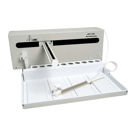
CETAC ASX-520
CETAC ASX-520HS
CETAC ASX-520/520HS with EXR-8 extended rack
CETAC ASX-1400
CETAC ASX-1600
PerkinElmer S10
Agilent SPS-3
Tubing connection information for some autosamplers is in the corresponding
Quick Installation Guide.
Updates
Updated versions of this manual may be available on the CETAC Web site:
www.cetac.com under Service & Support – Service Documents.
Rapid Sample Introduction System Standard
Components
The ASXPRESS PLUS Rapid Sample Introduction System module cases are made
of a high-strength aluminum alloy with an epoxy powder coating finish. The 6-
port injection valve is constructed of polyphenylene sulphide (PPS), an inert
and dimensionally stable material. The tubing is all inert PTFE (waste tubing
materials may vary by application).
The ASXPRESS PLUS system operates reliably under a wide variety of conditions.
Components in the sample flow path are inert, non-metallic materials; when
used at temperatures less than 135°C, they can withstand repeated exposure
to the following substances:

ASXPRESS PLUS Rapid Sample Introduction System Operator’s Manual
Chapter 1: Introduction
10
Predominantly aqueous solutions of strong acids (less than 40%).
Common organic solvents such as acetone, alcohols, ethyl acetate,
Methylethylketone (MEK), petroleum oils and derived fuels,
tetrachloroethylene, toluene, and xylene.
Prolonged or repeated exposure to temperatures greater than 135°C and to the
following substances can cause failure of the flow path components:
• Solutions of concentrated acids (greater than 40%).
• Partially halogenated hydrocarbons or extremely aggressive organic solvents
(chloroform, methylene dichloride, 1,1,2-trichloroethane).
Figure 1-3 ASXPRESS PLUS Rapid Sample Introduction System—Front View
CAUTION
Valve/Pump
Module
Electronics Module
Vacuum Pump
“In” Port
Vacuum Pump
“Out” Port
6-
Port Injection
Valve
Sample Loop
Load LED
Inject LED
Busy LED

ASXPRESS PLUS Rapid Sample Introduction System Operator’s Manual
Chapter 1: Introduction
11
Figure 1-4 ASXPRESS PLUS Electronics Module—Back View. Some connectors
will not be used, depending on the system configuration.
Input from Power
Supply
Power Switch
Output to
Valve/Pump
Module
Output to
Autosampler
(Serial)
Output to
Syringe Pump
(Serial)
Output to
External Pump
Input from Host PC:
Autosampler Commands
(Serial or USB)
Input from Host PC:
ASXPRESS PLUS
Configuration
(Serial or USB)

ASXPRESS PLUS Rapid Sample Introduction System Operator’s Manual
Chapter 1: Introduction
12
The following standard components are also shipped with the ASXPRESS PLUS
system:
Power Supply. A desktop power supply powers the electronics module
and valve/pump module.
Sample Loops. For aqueous applications, the following standard sized
sample loops are provided: 0.7 mL, 1.00 mL, 1.50 mL, 2.00 mL, 2.50 mL,
3.00 mL, and 4.00 mL. For oils applications, the sample loops provided are:
0.91 mL, 1.02 mL, 1.14 mL, 1.25 mL, 1.36 mL, and 1.48 mL. Additional loops
are available.
1.0mm Sample Probe. A 1.0mm ID sample probe must be used on the
connected CETAC autosampler to operate properly with the ASXPRESS PLUS
system. For the ASX-1400 autosampler, a sample probe/stirrer holder block
is supplied to fit the new sample probe.
Xpress Rinse Station. The Xpress rinse station is specially designed to
accommodate rapid flow of rinse solution through the probe. The Xpress
rinse station will be included in the kit, and must be installed.
Communication Cables. Two A-B USB cables and two female-female DB-9
RS-232 cables are included.
ASXpress CD. The CD contains:
Xpress Configuration Tool software
C-Term software (terminal program)
USB device drivers
Firmware
This manual
Quick Installation Guide
Spare parts catalog
Other application-specific information
Supplied components depend on the application and autosampler. See the
packing list in the shipping container to see exactly which components are
supplied.

ASXPRESS PLUS Rapid Sample Introduction System Operator’s Manual
Chapter 1: Introduction
13
Optional Accessories/Components
Refer to the ASXPRESS PLUS Rapid Sample Introduction System Accessories and
Supplies Catalog for a full listing of accessories and spare parts.
Articulating Mounting System. This mounting system allows for stable
and secure, close proximity placement and mounting of the Valve/Pump
Module near the instrument nebulizer.
Alternate Sample Loops. Alternate sample loop sizes are available as
spares. Available sizes for aqueous applications include:
0.70 mL
1.0 mL
1.25 mL
1.5 mL
2.0 mL
2.5 mL
3.0 mL
3.5 mL
4.0 mL
4.5 mL
5.0 mL
Available sizes for oils applications include:
0.91 mL
1.02 mL
1.14 mL
1.25 mL
1.36 mL
1.48 mL.
2.0 mL
2.5 mL
3.0 mL
NOTE
Please refer to the ASXPRESS PLUS Rapid Sample Introduction System Accessories
and Supplies Catalog or contact CETAC Technologies if you need additional
accessories not listed, need added features to integrate the ASXPRESS PLUS
Rapid Sample Introduction System into your analytical system, or have unique
requirements. Research and development of new features and accessories for
the ASXPRESS PLUS Rapid Sample Introduction System, often inspired by
customer requests, is a continuing activity of CETAC Technologies.
Additional Equipment Required
In addition to the provided equipment, you will need:
A host computer which has been configured with the ICP software. This
computer must have an additional free USB or serial port beyond the ports
required to control the autosampler, spectrometer, and other system
components.

ASXPRESS PLUS Rapid Sample Introduction System Operator’s Manual
Chapter 1: Introduction
14
Where to Go for More Information
In addition to this manual, you can refer to the following resources:
The ASXpress Plus Quick Installation Guide (In many cases, a version
specific to your autosampler will be included with the installation kit.)
The software manual for the ICP/ICP-MS instrument you are using
The operator’s manual for the autosampler you are using
The CETAC Technologies Web site: www.cetac.com
CETAC Technologies Customer Service and Support:
1 (800) 369-2822
1 (402) 733-2829
1 (402) 733-1932 (Fax)
E-mail: custserv@cetac.com
Installation Overview
In most cases, a CETAC representative will assist with the installation of the
ASXPRESS PLUS Rapid Sample Introduction System.
The following chapters describe how to install the ASXPRESS PLUS Rapid Sample
Introduction System:
1 Select a location and unpack the ASXPRESS PLUS Rapid Sample Introduction
System. (Chapter 2, page 15)
2 Set up your autosampler.
This procedure depends on which autosampler and pump you are using.
3 Install the valve/pump module. (Chapter 6, page 67)
Connect tubing from the autosampler to the valve/pump module, then to
the nebulizer.
4Install the electronics module. (Chapter 7, page 77)
Connect the electronics module to a power source and to the valve/pump
module, then set up the electronics module to intercept communications
between the ICP host computer and the autosampler.
5Install the software. (Chapter 8, page 87)
6Configure timing parameters. (Chapter 9, page 99)
7Begin using the ASXPRESS PLUS Rapid Sample Introduction System. (Chapter 10,
page 107)

15
2Preparing for
Installation
Installing the ASXPRESS PLUS system requires preparation. Before you install the
ASXPRESS PLUS Rapid Sample Introduction System, you should evaluate the
physical arrangement of the laboratory to choose a suitable location which
allows placement of the ASXPRESS PLUS valve/pump module as close to the
nebulizer as possible. Once you choose a location, you must carefully unpack
the system prior to beginning the installation.
This chapter discusses what requirements must be met when you choose a
location for the ASXPRESS PLUS Rapid Sample Introduction System. It also
describes how to unpack the system before installation.
Choosing a Location
Choosing a location for the system involves evaluating the lab environment for
the availability of space, liquid waste routing and power. For the system to
function optimally, the location you select must meet specific requirements
associated with each of these items. The following sections discuss space,
water, and power requirements.

ASXPRESS PLUS Rapid Sample Introduction System Operator’s Manual
Chapter 2: Preparing for Installation
16
Space Requirements
Most analytical applications benefit from utilizing the shortest sample flow
path. Therefore, you should place the valve/pump module in close proximity to
the nebulizer of the analytical instrument. The required space for ASXPRESS
PLUS system installation includes separate accommodations for both the
valve/pump module and for the electronics module as follows:
Valve/Pump Module Electronics Module
Height 12.8 cm 25.4 cm
Width 5.8 cm 8.3 cm
Depth 21.7 cm 20.0 cm
Weight 1.3 kg (2.9 lbs) 1.4 kg (3.0 lbs)
Table 2-1: Physical Characteristics
The above listed dimensions allows for space to accommodate the sample loop
and connection tubing, as well as cabling.
In most cases, you will also need to allow space just behind or beside the
autosampler for an external rinse pump (approximately 14x10x10 cm).
Liquid Waste Routing Requirements
Ensure that there is a liquid waste receptacle within two meters of the
ASXPRESS PLUS valve/pump module. The waste receptacle inlet should be at
least 30 to 60 centimeters lower than the ASXPRESS PLUS Rapid Sample
Introduction System vacuum pump outlet and set up so that the rinse drain
tubing drops directly into the waste receptacle with no coiling and without
being submerged below the liquid level of the waste receptacle.
Power Requirements
The ASXPRESS PLUS electronics module receives power through the connection
to the external desktop power supply. Place the ASXPRESS PLUS electronics
module within 3 meters of a power outlet.
SHOCK AND FIRE HAZARD
Use only the provided power supply. The power supply must be plugged
into an outlet which has a protective ground connection.
The ASXPRESS PLUS system is intended to operate from DC power supplied
through the provided power supply. The power supply is provided power
through an AC power source that will not apply more than 240VAC between
the supply conductors and ground. A protective ground connection by way of
the grounding connector in the power cord is required for safe operation.
Ensure that you position the electronics module so that the location where the
power supply cord plugs into it is easily accessible (is not blocked) and it can
be quickly disconnected if needed.
The power supply socket is on the back of the electronics module next to the
power switch. Connect the power supply to the electronics module first and
then connect a line cord to the power supply. Do not apply power to the power
supply until ready to operate the autosampler.
WARNING

ASXPRESS PLUS Rapid Sample Introduction System Operator’s Manual
Chapter 2: Preparing for Installation
17
The valve/pump module receives power from the electronics module.
In case of hazard, the autosampler should be disconnected from the power
source as well as from the ASXPRESS PLUS system.
Unpacking the ASXPRESS PLUS Rapid Sample
Introduction System
Inspect external packaging upon receipt for signs of shipping damage. Inspect
all items during unpacking and notify the carrier immediately of any concealed
damage. Check for kinked tubing in the sample loops or other tubing.
If the system is shipped or removed from storage during cold weather, allow
the packaged equipment to equilibrate to room temperature before opening
and exposing to warm, humid air. It is usually sufficient to provide four to eight
hours for this purpose.
If condensation forms on or inside the ASXPRESS PLUS Rapid Sample Introduction
System, allow it to dry thoroughly before connecting it to a power source and
operating it. Failure to do so may cause equipment damage.
Remove the packing checklist from the shipping container, and check off items
against it. Leave accessories in the packing until you are ready to install them.
NOTE
Keep the factory packaging for use in case the product ever needs to be
returned or shipped to another location.
CAUTION

ASXPRESS PLUS Rapid Sample Introduction System Operator’s Manual
Chapter 2: Preparing for Installation
18
This page is intentionally blank.

19
3Preparing an
ASX-500/510
Autosampler
To work properly with the ASXPRESS PLUS Rapid Sample Introduction System, an
ASX-500 or ASX-510 autosampler will require:
Upgraded firmware (on an EPROM chip, if CETAC determines that it is
needed for your autosampler)
Xpress rinse station
External pump (required to achieve adequate sample and rinse flow rate)
and associated plumbing
1.0mm ID sample probe

ASXPRESS PLUS Rapid Sample Introduction System Operator’s Manual
Chapter 3: Preparing an ASX-500/510 Autosampler
20
INJURY HAZARD
Ensure that AC power to the autosampler is off before proceeding with
installation. If power to the autosampler is not turned off, the autosampler
could begin moving while you are working on it.
The plumbing connections should be made without using tools. In fact, using tools
such as screwdrivers or pliers to perform installation tasks may result in a damaged
or unusable instrument. Do not tighten fittings with anything other than your
fingers.
Upgrade the Firmware
In some cases, it may be necessary to upgrade the firmware in the autosampler.
If you are unsure whether to upgrade the firmware, contact CETAC
Technologies for advice.
Up-to-date firmware is required to allow the autosampler to respond correctly
to the ASXPRESS PLUS Rapid Sample Introduction System.
The ASX-500/510 firmware is stored on an EPROM chip.
Checking the Firmware Version
If you think the autosampler might already have the correct firmware, check
the version before replacing the EPROM:
1Connect the autosampler to the host computer.
2Establish communication using C-TERM or another terminal program.
See “Operating a CETAC Autosampler Using a Terminal Program” on page
137 for instructions.
3Enter the VER command.
If the firmware version is the same as the provided EPROM chip, upgrading
is not required.
Upgrading the EPROM
1Follow the instructions in the document Firmware Change Procedure for ASX-
510 supplied on the CD-ROM.
The document is also available in the service documents section of the
CETAC Technologies Web site, www.cetac.com.
2Do not reinstall the rinse station, as you will need to replace the rinse station
anyway.
WARNING
CAUTION
Other manuals for ASXPRESS PLUS
1
Table of contents
Other CETAC Laboratory Equipment manuals

CETAC
CETAC ASX-260 User manual

CETAC
CETAC ASX-1400 User manual

CETAC
CETAC ASX-520 Use and care manual

CETAC
CETAC ASX-510 Guide

CETAC
CETAC ASXpress User manual

CETAC
CETAC ASX-520 Instruction Manual

CETAC
CETAC LSX-213 User manual

CETAC
CETAC ASX-500 Series User manual

CETAC
CETAC ASX-520 User manual

CETAC
CETAC ASX-510 Guide