CGM CGM 507 User manual

-ITA-
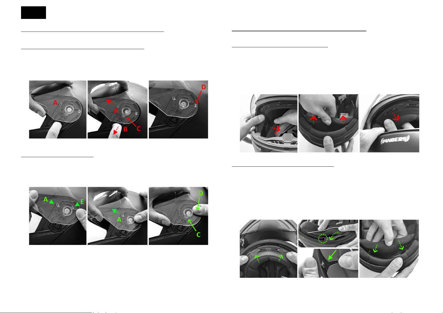
ISTRUZIONI PER LO SMONTAGGIO (A) E IL MONTAGGIO (B) DELLA VISIERA
Smontaggio della visiera e completa rimozione del kit di fissaggio.
A1. Aprire del tutto la visiera portando il gancio A l’ultima posizione, come in Figura 1.
A2. Mantenere tirata la leva B per liberare il gancio C e, contemporaneamente, tirare in avanti la visiera
fino a liberare il gancio A, come in Figura 2.
A3. A questo punto tirare verso di sé la visiera per liberare il gancio D mostrato in Figura 3.
Figura 1.
Figura 2.
Figura 3.
Montaggio della visiera e del kit di fissaggio.
B1. Allineare il gancio A alla posizione più alta del kit di fissaggio ed allinea il gancio E come in Figura 4.
B2. Mantenere il gancio E in posizione e tirare in avanti la visiera sfruttando il suo sistema di ritenzione
per bloccare il gancio A, come mostrato in Figura 5.
B3. Esercitare una pressione nel punto indicato in Figura 6 per far scattare i blocc i dei ganci C e D.
Figura 4.
Figura 5.
Figura 6.
NB. Le figure si riferiscono alle componenti del sistema di fissaggio sul lato sinistro del casco. La procedura
è la medesima per il lato destro, dove le componenti sono speculari.
CGM 507
CGM.507-A.01
ISTRUZIONI PER LA RIMOZIONE (A) E IL FISSAGGIO (B) DELL’IMBOTTITURA INTERNA
La cuffia centrale ed i guanciali possono essere facilmente rimossi per il lavaggio.
Rimuovere prima i guanciali e successivamente la cuffia.
A1. Rimuovere i guanciali sganciando i bottoni automatici e sfilando la pattina in plastica (Figura 7).
A2. Rimuovere la cuffia partendo dal retro, sganciando i due bottoni automatici ed esercitando una
leggera trazione verso l’interno del casco, come in Figura 8.
A3. Sganciare la piastrina di fissaggio dal telaietto in plastica esercitando una leggera trazione nei tre punti
di ancoraggio, iniziando da uno dei due punti esterni, come in Figura 9.
A4. Per rimuovere il coprimento è sufficiente tirare leggermente il telaietto in plastica con cui è fissato
alla mentoniera.
Figura 7. Figura 8. Figura 9.
Fissare prima la cuffia centrale e successivamente i guanciali.
B1. Posizionare la cuffia all’interno del casco con la piastrina di fissaggio rivolta sul lato frontale, inserirla
nel telaietto e spingere fino ad agganciare i punti di ancoraggio, come in Figura 10.
Agganciare i due bottoni automatici posti sul lato posteriore.
B2. Sistemare il guanciale nella sua sede, inserendo preventivamente il cinturino nella sua asola. Infilare
poi la pattina in plastica tra la calotta esterno ed il polistirolo rivestito, come in Figura 11a, avendo
cura di far scorrere la guida nella vite presente tra calotta ed EPS (Figura 11b). Infine, fissare i bottoni
automatici (Figura 12).
B3. Per fissare il coprimento è sufficiente agganciare il telaietto in plastica alla base della mentoniera.
Figura 10. Figura 11a-11b. Figura 12.
-ENG-
HOW-TO DISASSEMBY (A) AND HOW-TO ASSEMBLY (B) THE VISOR
Disassembly of the visor and complete removal of the fixing system.
A1. Fully open the visor setting the hook A on upper position, as shown in Figure 1.
A2. Keep the lever B pulled to release the lock C and, at the same time, pull forward the visor to release
the hook A, as in Figure 2.
A3. At this point pull the visor towards you to help the release of the lock D shown in Figure 3.
Figure 1.
Figure 2.
Figure 3.
Assembly of the visor and fixing system.
B1. Set the hook A on the upper position of the fixing system and set the hook E as in the Figure 4.
B2. old in place the hook E and, using the visor retention system, pull forward the visor to fix the hook
A, as shown in the Figure 5.
B3. Press the point indicated in Figure 6 to snap the locks of hooks C and D.
Figura 4.
Figura 5.
Figura 6.
NOTE. The figures refer to the components of the fixing system on the left side of the helmet. The
procedure is the same for the right side, where the components are specular.
CGM 507
CGM.507-A.01
HOW-TO REMOVE (A) AND HOW-TO FIX (B) THE INNER LINING
The main liner and the cheek pads can be easily removed for washing.
First remove the cheek pads and then the main liner.
A1. Remove the cheek pads by detaching the snap buttons and pulling the plastic flap (Figure 7).
A2. Remove the main lining starting from the rear, by detaching the two snap buttons and pulling lightly
towards the inside of helmet, as in Figure 8.
A3. Release the fixing plate from the plastic frame by pulling lightly on the three anchor points, starting
form one of the side points, as in Figure 9.
A4. To remove the chin protector simply pull out the plastic frame which it is fixed to the chin guard
slightly.
Figure 7. Figure 8. Figure 9.
First fix the main liner padding and then the cheek pads.
B1. Place the main liner padding inside the helmet with the fixing plate facing the front side, insert the
fixing plate in the frame and push to hook the anchor points as in the Figure 10.
ook the two snap buttons on the rear side.
B2. Place the cheek pad in housing, by inserting the chin strap in its slot in advance. Then slide the plastic
flap between the shell and EPS liner, as in Figure 11a, taking care to slide the guide into the screw
between the shell and the EPS (Figure 11b). Finally, fasten the snap buttons (Figure 12).
B3. To fix the chin protector simply hook the plastic frame to the base of the chin guard. slide the plastic
flap between the shell and EPS liner, taking care to restore the shell trim over the chin protector.
Figura 10. Figura 11a-11b. Figura 12.

ATTENZIONE
W ARNING
www.cgmitalia.net


Grazie per aver acquistato un prodoo CGM!
La soddisfazione dei nostri clien è importante per noi: se non sei
soddisfao del tuo acquisto o se hai riscontrato qualche problema,
contaaci all’indirizzo info@cgmitalia.net e ci adopereremo per
risolverlo.
IT
This manual suits for next models
1
Table of contents
Other CGM Motorcycle Accessories manuals


