7
4.4.2 Fréquence
nUtilisation : 40 Hz à10 kHz.
Limiter à1 kHz si fonctionnement permanent à200 A~.
4.4.3 Conditions d’environnement
nUtilisation en intérieur
nAltitude : < 2000 m
nConditions climatiques : de -10 à+55°C et HR < 85%
nNe pas exposer aux projections d’eau
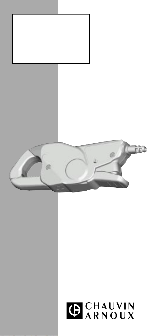
4.5 Dimensions et masse
nDimensions hors tout : 135 x 50 x 30 mm
nMasse : environ 180 g.
nOuverture des mâchoires : 21 mm
nHauteur des mâchoires ouvertes : 69 mm
nCapacitéd’enserrage maxi : câble Ø20 mm ou barre 20 x 5 mm.
4.6 Conformitéauxnormesinternationales
4.6.1 Sécuritéélectrique (selon IEC 1010-1 et 1010-2-032)
nDouble isolation nDegréde pollution 2
nCatégorie d’installation III nTension de service 600 V
4.6.2 Compatibilitéélectromagnétique conforme CE
nEmissivité(selon EN 50081-1) nSusceptibilité(selon EN 50082-2)
4.6.3 Protections mécaniques
nIndice de protection IP40 (selon IEC 529) avec les mâchoires fermées
et IP30 mâchoires ouvertes.
4.6.4 Auto-extinguibilité
nMâchoires :V0 (selon UL 94).
5. MAINTENANCE
Pour la maintenance,utilisez seulement les pièces de rechange qui ont
étéspécifiées. Le fabricant ne pourra être tenu pour responsable de
tout accident survenu suite àune réparation effectuée en dehors de
son service après-vente ou des réparateurs agréés.
5.1 Entretien
La pince ne doit pas enserrer de câble et être déconnectée de l’appareil de
mesure. Ne pas projeter d’eau sur la pince.
nMaintenir l’entrefer des mâchoires en parfait état de propreté. Enlever
les poussières avec un chiffon doux et sec.De temps en temps, passer
unchiffonimprégnéd’huile sur les fers pour éviterla formationde rouille.
nNettoyer leboîtier avecunchiffon légèrement imbibéd’eausavonneuse.
Rincer avec un chiffon humide. Ensuite, sécher rapidement avec un
chiffon ou de l’air pulséà70°C maxi.
5.2 Vérification métrologique
nComme tous les appareils de mesure ou d’essais, une vérification
périodique est nécessaire.
Pour les vérifications et étalonnages de vos appareils, adressez-vous ànos labo-
ratoires de métrologie accrédités COFRAC ou aux agences MANUMESURE.
Renseignements et coordonnées sur demande :
Tél. : 02 31 64 51 43 Fax : 02 31 64 51 09
nRéparation sous garantie et hors garantie.
Adressez vos appareils àl’une des agences régionales MANUMESURE,
agréées CHAUVIN ARNOUX.
Renseignements et coordonnées sur demande :
Tél. : 02 31 64 51 43 Fax : 02 31 64 51 09
nRéparation hors de France métropolitaine.
Pour toute intervention sous garantie ou hors garantie, retournez l’appareil
àvotre distributeur.
6. GARANTIE
Notre garantie s’exerce, sauf stipulation expresse, pendant douze mois
après la date de mise àdisposition du matériel (extrait de nos Conditions
Générales de Vente, communiquées sur demande).