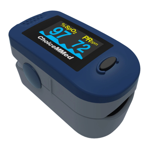
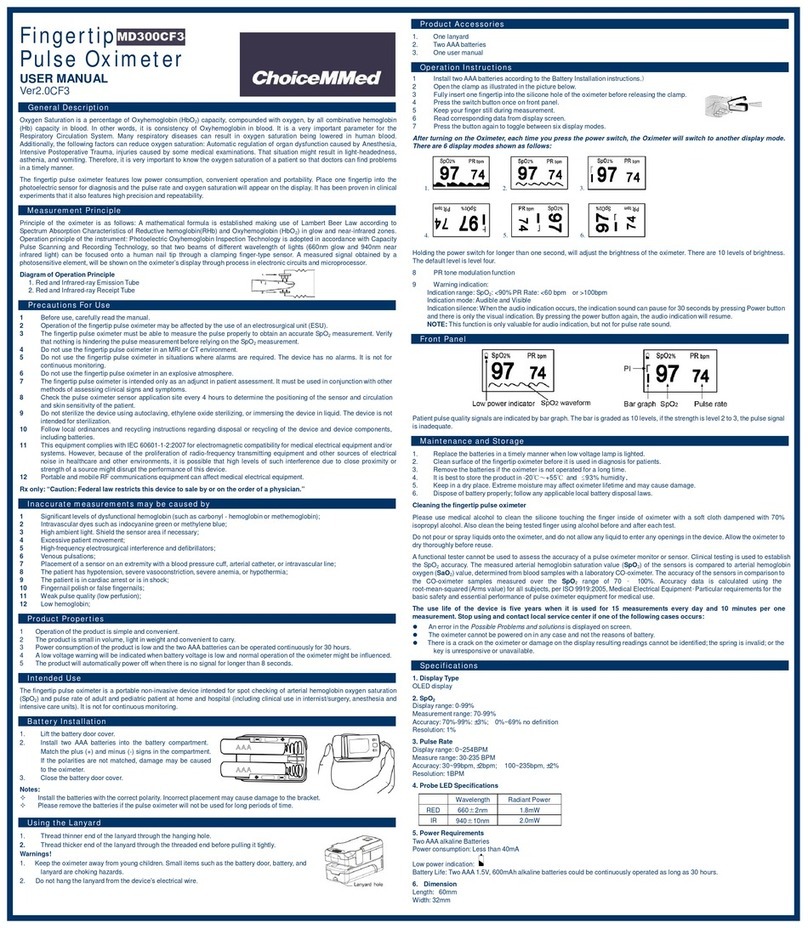
ChoiceMMed MD300 User manual

PULSE OXIMETER
INSTRUCTION
MANUAL
V1.0M122

V1.0M122 PULSE OXIMETER INSTRUCTION MANUAL
Copyright
Our company owns all rights of this unpublished work and intends to maintain it as a
confidential work. We may also seek to maintain this work as an unpublished copyright.
This publication is to be used solely for the purpose of reference or operation of our
device. No part of this work can be disseminated for other purposes.
In the event of inadvertent or deliberate publication, we intend to enforce its rights to this
work under copyright laws as a published work. Those having access to this work may
not copy, use, or disclose the information in this work unless expressly authorized by our
company.
All information contained in this publication is believed to be correct. We shall not be
liable for errors contained herein nor for incidental or consequential damages in
connection with the furnishing, performance, or use of this material. The information this
publication refers to is protected by copyrights or patents and does not convey any
license under the patent rights of our company, nor the rights of others. We do not
assume any liability arising out of any infringements of patents or other rights of third
parties.
Content of the manual is subject to change without prior notice.
ALL RIGHTS RESERVED
Bluetooth® and the Bluetooth® Logo are registered trademarks of Bluetooth® SIG, Inc.
V1.0M122
Issuedate:5
th January, 2010

V1.0M122 PULSE OXIMETER INSTRUCTION MANUAL
Content
1 Introduction...........................................................................................3
1.1 Brief Introduction...........................................................................3
1.2 Safety Information .........................................................................3
1.3 Electromagnetism Interference ....................................................5
2 General Descriptions ............................................................................6
2.1 Appearance ....................................................................................6
2.2 Explanation of Symbols .................................................................8
2.3 Power Supply..................................................................................9
2.4 Product Features .........................................................................11
3 Install the Probe..................................................................................11
4 Setting ID, Date and Time...................................................................12
4.1 Date & Time Settings...................................................................12
4.2 ID number Setting ........................................................................13
5 Take a Measurement...........................................................................14
6 Other Settings .....................................................................................15
6.1 Alarm Setting ...............................................................................15
6.2 Data Management ........................................................................17
6.3 System setting .............................................................................20
7 Maintain and Repair ............................................................................22
7.1 Maintenance.................................................................................22
7.2 Safety Checks ..............................................................................23
7.3 Calibration and Verification.........................................................24
7.4 Trouble Shooting..........................................................................25
7.5 Warranty and Repair ....................................................................25
7.6 Storage and Transportation ........................................................27
APPENDIX A Specifications ...................................................................27

1 Introduction
1.1 Brief Introduction
Thank you for purchasing the handheld pulse oximeter. The main functions of the device
include SpO2and PR measurements, visual and audible alarm, batteries charging, data
storage and review and USB cable&Bluetooth transferring, etc. Please read this manual
carefully before using the device.
Intended use:
The pulse oximeter is intended for spot checking, displaying, storing and transmitting
Haemoglobin Saturation and pulse rate of single adult, pediatric and neonatal patient in
hospital (including clinical use in surgeries, anesthesia, intensive care and etc.), in home
care environment, and social medical organizations.
Notes:
)The illustration applied in the manual may differ slightly from actual device.
)The device is designed of handheld structure and please be sure not to turn
upside down when using it.
1.2 Safety Information
Conception of Warning, Precaution and Note
The Warning, precaution and Notice at this document are special information in favor of
user’s operation.
¾Warning - Indicates a potential hazard or unsafe practice that, if not avoided, will
result in death or serious injury.
¾Caution - Indicates a potential hazard or unsafe practice that, if not avoided, could
result in minor personal injury or product/property damage.
¾Note: - Provides application tips or other useful information to ensure that you get
the most from your product.
Warnings
zThe handheld pulse oximeter should be confined to sophisticated operator exclusively.
Prior to application, users should follow instructions listed in this manual, otherwise any
wrong operation may cause serious damage. Our company will assume no warranty for
using this equipment improperly.
zDo not use the oximeter in the presence of flammable anesthetics, vapors or liquids.
zDo not use the oximeter in an MRI or CT environment.

V1.0M122 PULSEOXIMETEROPERATOR'SMANUAL
4
zThis equipment is for use in the medical field, and measurement results only serve as a
reference for any relevant treatment.
zConnect the probe correctly; please see the directions for use of any accessories.
zPlease follow the doctor’s suggestions when starting to monitor the vital sign
parameters.
zWhen connecting this device to other peripherals, make sure that you are qualified to
operate this device. Any peripheral must be certified according to the protocol of IEC
950 and IEC 601-1-1. Any input/output device should follow the protocol of IEC
601-1-1.
zConsidering the probe is a sensitive device so please strictly follow the probe
application instructions.
zThe malfunction of probe may cause inaccurate data which serves as a foundation to
treat patients, so make sure to pay more attention to the probe and inspect it usually.
zThe worn-out data cables may cause inaccurate data which is used as a reference to
treat patients, so please pay attention to the data cable and check it frequently.
zDo not touch the AC adapter with wet hands. Otherwise,You may suffer electric shock.
zThe disposable accessories should not be cycled.
zThis device complies with Part 15 of the FCC Rules. Operation is subject to the
following two conditions: (1) this device may not cause harmful interference, and (2)
this device must accept any interference received, including interference that may
cause undesired operation.
Cautions
zClean the probe with an H2O solution and a neutral detergent. Don’t submerge the
probe. Do not use in autoclave (sterilizer).
zThis device is intended for use by persons trained in professional health care. The
operator must be thoroughly familiar with the information in this manual before using
the device.
zBefore cleaning or disinfecting the probe, unplug it from the oximeter to prevent probe
or oximeter from being damaged, and to protect user under safety situation.
zTo avoid an electrical hazard, never immerse the unit in any liquid or attempt to clean it
with liquid cleaning agents. Always disconnect the device from AC adapter before
performing cleaning of maintenance.
zAlarm must be set up according to different situations of individual patient. Make sure
that chime sound can be activated when alarm function begins to work.
Notes

V1.0M122 PULSEOXIMETEROPERATOR'SMANUAL
5
zApplication of this device may influence the measuring accuracy in the background of
electromagnetic areas such as electro-surgery environment.
zSpO2measurements may be adversely affected in the presence of high ambient light.
Shield the probe area (with a surgical towel, for example) if necessary.
zDyes introduced into the bloodstream, such as methylene blue, indocyanine green,
indigo carmine, and fluorescein, may adversely affect the accuracy of the SpO2
reading.
zAny condition that restricts blood flow, such as use of a blood pressure cuff or extremes
in systemic vascular resistance, may cause a failure to determine accurate pulse rate
and SpO2readings.
zRemove fingernail polish or artificial fingernails before applying SpO2probes.
Fingernail polish or artificial fingernails may lead to inaccurate SpO2readings.
zHazards arising from software errors have been minimized. Hazard analysis conforms
to meet ISO14971: 2000 and EN60601-1-4: 1996. Significant levels of dysfunctional
hemoglogins, such as carboxyhemoglogin or methhemoglobin, will spawn an affection
of the accuracy of the SpO2measurement.
zOptical cross-talk can occur when two or more probes are located in adjoining area. It
can be eliminated by covering each site with opaque material. Optical cross-talk may
adversely affect the accuracy of the SpO2readings.
zObstructions or dirt on the probe’s red light or detector may cause a probe failure. Make
sure there are no obstructions and the probe is clean.
zThe AC adapter and accessories used with the device should be complied with the
requirement of IEC60601-1.
zFor routine equipment maintenance, please refer to the service procedures at the
associated section as indicated in the manual.
zAs to the other concerns for attention, please carefully look through the specific chapter
in this instruction.
1.3 Electromagnetism Interference
This oximeter is designed and tested in compliance with the EMC standard, complying
with the international standard for the EMC of the electronic medical device - IEC
60601-1-2. However, because of the proliferation of radio frequency transmitting
equipment and other sources of electrical noise in the health-care and home environments
(e.g. cellular phones, mobile two-way radios, electrical appliances), it is possible that high
levels of such interference due to close proximity or strength of a source, may result in
disruption of performance of this device.
V1.0M122 PULSEOXIMETEROPERATOR'SMANUAL
6
This apparatus complies with the IEC 60601-1-2 international standard. The requirements
of this international standard are: CISPR11, GROP1, and CLASS B.
2 General Descriptions
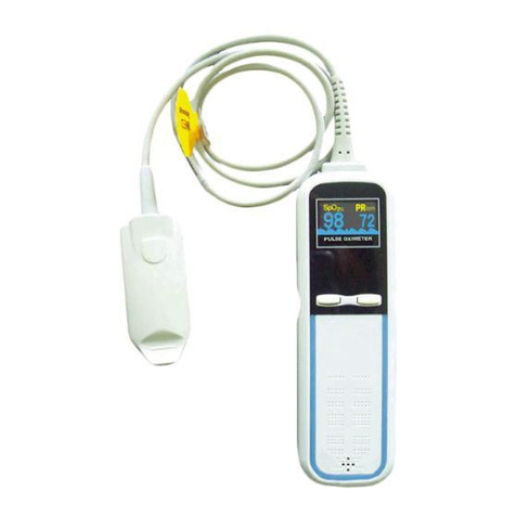
The handheld pulse oximeter adopts 2.8 inch TFT screen, which can display the SpO2%
and pulse rate value, other indication parameters, such as time, ID number, pulse
amplitude bar and battery power status, alarm limits and the connections of Bluetooth and
probe, etc.
2.1 Appearance
Fig.2-1
Description of Fig.2-1:
SpO2socket: for connecting the SpO2probe with the oximeter.
Alarm lamp: When SpO2or/and PR alarm occurs, It flashes(the color of the lamp is
yellow).
Up button: press this button to increase the value by one increment. Or press it and hold

V1.0M122 PULSEOXIMETEROPERATOR'SMANUAL
7
it down to continuously increase the value.
Down button: press this button to decrease the value by one decrement. Or press it and
hold it down to continually decrease the value.
Menu/Select button: for entering main menu, or confirming the selection/setting.
Alarm inhibit/off button: Press this button to inhibit alarm sound for 120 seconds. And
long press the button, power off the alarm.
Return/Lock button:On the measuring screen, it serves as Lock button;On the menu
and sub-menu screen, it serves as Return button.
Power switch: Press and hold it down for about 3 seconds to power it on, and for about 4
seconds to turn it off.
Charge indicator: During the oximeter is being charged, the lamp is flashing; when it is
charged to full, the lamp is lighted without flashing; And the lamp is not lighted when it is
not charged.
Adapter socket: for connecting the power adapter.
USB socket:designed to update the software of the device and only serves engineer.
Measurement screen:
Fig.2-2Digitaldisplay Fig.2-3Wavedisplay
1. Status bar 1&3: The status of the oximeter is shown on the bar.
2. Status bar 2&4: If the measured SpO2% or PR value exceeds the alarm limits, there will
be the corresponding information.
3SpO2%:SpO2area of display
◆It shows the oxygen saturation level of functional hemoglobin during normal
measurement.
◆The background color of the SpO2value is red when the SpO2is outside the alarm
limits.

V1.0M122 PULSEOXIMETEROPERATOR'SMANUAL
8
◆It shows two dashes throughout probe off and finger out conditions.
4:99: SpO2% upper alarm limit indicator
5:90: SpO2% lower alarm limit indicator
6:Pulse amplitude bar.
It indicates the dynamic pulse amplitude and rate. As the detected pulse becomes stronger,
more bars is illumined with each pulse. The reverse is true for weak pulses.
7:75: PR upper alarm limit indicator
8:60: PR lower alarm limit indicator
9:PR: PR area of display
◆It shows the pulse rate in beats per minute during normal measurement.
◆The background color of the PR value is yellow when the PR is outside the alarm
limits.
◆It shows three dashes throughout probe off and finger out conditions.
10.15:00: The current time.
2.2 Explanation of Symbols
Symbol Explanation Symbol Explanation
Type BF applied part IPX1
Protected form dripping water
ID indication
Attention, consult
ACCOMPANYING
DOCUMENTS
Audible alarm on
Audible alarm off/inhibition
It indicates alarm inhibition
when the countdown of 120s
displayed
Pulse Beep on Pulse Beep off
The adapter is connected Battery power indication

V1.0M122 PULSEOXIMETEROPERATOR'SMANUAL
9
Keyboard is unlocked Keyboard is locked
USB cable is connected USB cable disconnected
SpO2probe is inserted SpO2probe off
Bluetooth activated Bluetooth deactivated
2.3 Power Supply
2.3.1 Powered by batteries
Fig.2-4
Batteries Installation :
1) Open the battery cover: Rotate the fixing screw slightly in the rear panel to the position
which is marked with “ ” and then push the cover as indicated by arrowhead, as shown
in Fig.2-4.
2) Install 3 batteries lightly as indicated by the polarity signs in battery housing.
Note: Make sure the polarities of the batteries are correct.
3) Close battery housing cover
Close the battery housing cover and rotate the screw to the position which is marked with

V1.0M122 PULSEOXIMETEROPERATOR'SMANUAL
10
. And the batteries are locked.
Battery life and replacement
There are five shapes of the indicator: the centre with 4 bars(full), 3 bars, 2 bars, 1 bar,
empty and the frame in red. That the frame of indicator become red means few of battery
capacity remains. You should replace the batteries with new ones timely. Or else, the
indicator displays with a red frame constantly until battery capacity reaches critical
condition (the battery voltage is 3.5V±1V) at which time the unit shuts down.
Cautions!
Be sure to install batteries with correct polarities.
Only the approved batteries are recommended to be used..
Do not use batteries not specified for this unit.
Do not dispose of batteries in fire.
If battery fluid gets on your skin or clothing, rinse with plenty of clean water
immediately.
Remove the batteries from this unit when you are not going to use it for a long
period of time (approximately one month).
Do not use batteries of different types together.
Do not use new and used batteries together.
Dispose of batteries in accordance with the local ordinances and regulations.
2.3.2 Charging Batteries through adapter
To charge, please ensure the installed batteries are NI-MH ones. Firstly connect the
device with the oximeter and secondly with the wall outlet by adapter, and then press and
hold the power switch down for 3 seconds to power the device on.
A prompt window appears enquiring you “Are the batteries NI-MH ones?”, select “Yes” to
charge them or “No” to abandon charge and the device can be powered by wall outlet.
2.3.3 Charging Batteries by charger stand
The device can also be charged by charger stand provided with the oximeter. For more
information, refer to “Charger Stand Instruction Manual”.
Note:
1. To avoid the device from being damaged due to shot circuit, please keep the adapter is
firstly connected with the oximeter and secondly with the wall outlet. While disconnected
the connection, please keep the adapter is firstly disconnected from the wall outlet and
then disconnected from the oximeter.
2. During battery charge, the “Power Auto” and “Brightness” item can not be accessed.

V1.0M122 PULSEOXIMETEROPERATOR'SMANUAL
11
3. It is not recommended to measure SpO2during the oximeter is powered by wall outlet or
being charged, for the damages and injuries may be caused to the device or users.
4. DO NOT charge when the non-rechargeable batteries are installed, otherwise, the
damages or injuries may be caused to the devices or users.
2.4 Product Features
Simple to use and easy to operate.
Compact, light in weight and convenient to carry.
TFT display with adjustable backlight displays SpO2, pulse rate, pulse amplitude bar,
etc.
Up to 127 patients’ ID and 72-hour records storage.
Visual and three-level audible alarms, Battery power low alarm.
Adjustable pulse beep and backlight.
Data transfer to PC for review by Bluetooth or USB cable
Powered by three AA alkaline/ NI-MH batteries.
Battery charge function with adapter or charge stander(optional).
Suitable for adult, pediatric and neonatal users.
3 Install SpO2 Probe
The SpO2Probe is shown in the following figure:
Fig.3-1
Insert the SpO2probe to the socket, as shown in Fig.3-1. Then indicator is shown on
the display (refer to Fig.2). If the SpO2probe is disconnected from the unit,the indicator
appears and the prompt “Probe Off!!!” appears in the status column.

V1.0M122 PULSEOXIMETEROPERATOR'SMANUAL
12
The socket is also used for USB cable connected with the PC for data transmission. For
more information on data transmission and data management,refer to corresponding
software instruction manual.
4 Setting ID, Date and Time
Always set the date and time before using the unit for the first time. Set different ID
numbers for different users.
Check the date and time are correct before using the unit,and reset them if necessary. The
date and time are important indicators when a measurement is taken.
4.1 Date & Time Settings
Set the correct time according to the following steps:
1) Press the power switch for 3 seconds to power on the oximeter and then press the
menu button to enter the main menu, refer to the fig.4-1.
Fig.4-1
2) Press the Down button to select “Date and Time” item, and then press the Menu button
to enter the time setup screen,refer to Fig.4-2.

V1.0M122 PULSEOXIMETEROPERATOR'SMANUAL
13
Fig.4-2
Fig.4-3
Pick different sub-items to set and press the Select button to highlight it and then using the
Up or Down button to adjust the value. At last, press the Select button to confirm.
Set other sub-items of data and time according to the “Year setting” illustrated in the above
figures 4-2&4-3.
4.2 ID number Setting
Enter the “User ID Setting” from the main menu screen, refer to Fig.4-4. Press the Select
button to make the User ID number highlighted, and then press the Up or Down button to
increase or decrease the ID number, and then press the Select button to confirm your
settings. The range of ID number is: 001-127.

V1.0M122 PULSEOXIMETEROPERATOR'SMANUAL
14
Fig. 4-4
5 Take a Measurement
Before taking a measurement:
zSelect the suitable probe in terms of type and dimension.
zPlug probe into SpO2socket on top panel of pulse oximeter.
zClip the patient finger to the rational position of the probe as the illustration as Fig.5-1.
Fig.5-1 Placement of the probe
Note:If the finger is not in the probe, “Finger Out!!” will be shown.
Warnings!
zThe measurement would not be performed if the following instances come across
in operation:
zShock
zLow temperature of hand
zHave taken vascular activity medicine
zAnemia
zcarboxyhemoglobin
zmethemoglobin
zmethylene blue
zIndigo carmine
zOnly use the SpO2probes provided by manufacturer for SpO2measurements.
Other SpO2probes may cause improper performance.
zDo not use the SpO2probe with exposed optical components.
zExcessive patient movement may cause inaccurate measurements.
zTissue damage can be caused by incorrect application or use of probe, for
example by wrapping the probe too tightly. Inspect the probe site to ensure skin

V1.0M122 PULSEOXIMETEROPERATOR'SMANUAL
15
integrity and correct positioning and adhesion of the probe. More frequently
inspection should be taken depend on different patients if necessary.
zInaccurate measurements may be caused by:
zIncorrect application or use of probe
zSignificant levels of dysfunctional hemoglobins (such as carboxyhemoglobin or
methemoglobin)
zIntravascular dyes such as indocyanine green or methylene blue
zExposure to excessive illumination, such as surgical lamps (especially ones with a
xenon light source), bilirubin lamps, fluorescent lights, infrared heating lamps, or
direct sunlight
zHigh-frequency electro surgical interference and defibrillators
zVenous pulsations
zPlacement of a probe on an extremity with a blood pressure cuff, arterial
catheter, or intravascular line.
zThe patient has hypotension, severe vasoconstriction, severe anemia, or
hypothermia
zThere is arterial occlusion proximal to the probe
zThe patient is in cardiac arrest or is in shock
zLoss of pulse signal can occur in any of the following situations:
zThe probe is too tight
zThere is excessive illumination from light sources such as a surgical lamp, a
bilirubin lamp, or sunlight
zA blood pressure cuff is inflated on the same extremity as the one to which an
SpO2probe is attached
Note:SpO2probe should obviate the light source, e.g. radial lamp or infrared lamp.
The measured results are recorded into the memory of the oximeter, and Store up to
72-hours SpO2% and Pulse rate value, the time interval is 4 seconds. When the
memory is full, a prompt window of “Space Expire!” appears. To recorded the
newest measurements, you can delete the old ones for free space.
6 Other Settings
6.1 Alarm Setting
From the main menu, select and enter the “Alarm setting” screen, refer to Fig.6-1.
1) SpO2alarm setup
To set SpO2alarm high limit, In the “Alarm setting” screen, press the Up or Down button to
select the “High limit(SpO2)”. And then press the Select button to highlight the value.
Press the Up or the Down button to adjust the value, and at last press the Select button to
finish the setting of SpO2high limit. The range of SpO2high limit is 71%-100%.

V1.0M122 PULSEOXIMETEROPERATOR'SMANUAL
16
Fig.6-1
Set the low limit for SpO2 as the above steps of SpO2 high limit settings. The range of
SpO2 lower limit is 70%-99%.
2) PR alarm setting
Also, the limits settings of PR are performed as similarly as the SpO2 limits. The range of
High limit is 31bpm-235bpm. And the range of low limit is 30bpm-234bpm.
3) Alarm on/off
In the Alarm Setting screen, press the Up or Down button to move the cursor to the
Alarm(SpO2 ) or Alarm(PR) sub-item, and press the Select button to it highlighted. Press
the Up or Down button to select ON or OFF(refer to Fig.6-2). And then press the Select
button to confirm your settings. If you set the SpO2 and/or PR alarm off, the corresponding
limits on the measurement display is crossed with “×”.
Fig.6-2
ALARM PRIORITY:
There are three-level priorities for selection.
High priority: indicates the patient is in the very dangerous situation.
Medium priority: indicates the warnings should be paid attention to.
Low priority: indicates the technical alarm caused by the device itself.
Alarms of the oximeter include technical and physiological alarms. All the three priorities

V1.0M122 PULSEOXIMETEROPERATOR'SMANUAL
17
are divided by built-in module and can not be changed by user.
Assignment of priority:
High Medium Low
Paramter SpO2PR
Value Red Yellow
Alarm lamp Flashing with yellow Flashing with yellow
Lamp
Frequency
1.5Hz 0.5Hz
Audiblesound Di- Di – Di ----- Di - Di Di - Di - Di Di
Alarm cycle 3 s 5 s 20 s
Alarm info SpO2too high/low PR too high/low Probe off/Finger out
Notes:
1. The alarm sound will go on until alarm disappears or is turned off.
2. After silencing the alarm, the corresponding indicator will indicate this.
3. The power low alarm: the corresponding indication lamp will be flashing with a red
frame.
AUDIBLE ALARM INHIBITION/OFF:
Short press the button to silence the audible alarm for 2 minutes, the audible alarm
indicator will be displayed as ,together with the countdown from 120s to 0s,short
press it again,you can cancel alarm inhibition; Long press the button, the audible
alarm indicator will be displayed as which indicates the audible alarm off. And then
long press the button, you can activate the audible alarm again.
Warnings!
When an alarm occurs, check patients’ conditions immediately.
zCheck which parameter is alarming or which alarm is going on.
zCheck patient’s condition.
zSearch for the source of alarm.
zMake the alarm mute if necessary.
zCheck the alarm when no warning.
6.2 Data Management
From the main menu screen, select and enter the “Data Manage” screen, refer to fig.6-3.

V1.0M122 PULSEOXIMETEROPERATOR'SMANUAL
18
Fig.6-3
Press the Up button or Down button select the sub-item to set, and then press the Select
button to confirm or Return button to return to the previous screen.
6.2.1 Data Review
Pick ”Data Review” sub-item and enter by pressing the Select button. The screen as in
fig.6-4 will appear.
Press the Select button again, a dialog box will pop up, refer to fig.6-5. After selecting a ID
number, press the Up or Down button to select “Delete” or “Review” and then press the
Select button to confirm, you can delete or review all the records saved under the ID.
Fig.6-4 Fig.6-5
6.2.2 SpO2 Trend
Pick ” SpO2 Trend” sub-item and enter by pressing the Select button. The screen as in
fig.6-6 will appear.
Press the Select button again, a dialog box will pop up, refer to fig.6-7. After selecting a ID
number, press the Up or Down button to select “Delete” or “Review” and then press the

V1.0M122 PULSEOXIMETEROPERATOR'SMANUAL
19
Select button to confirm, you can delete or review all the SpO2trends saved under the ID.
Fig.6-6 Fig.6-7
6.2.3 PR Trend
The operation is referred to 6.2.2 SpO2 Trend.
Fig.6-8 Fig.6-9
6.2.4 Clear Data
Pick ”Clear Data” sub-item and enter by pressing the Select button. A dialog box will pop
up, refer to fig. 6-10. Press the Up or Down button to pick the Yes or No and then press the
Select button to determine whether to delete all the records.
Note: Pay attention to data deletion, as you make the deletion, the data will not be
restored again.
Table of contents
Other ChoiceMMed Medical Equipment manuals

ChoiceMMed
ChoiceMMed MD300C2 User manual

ChoiceMMed
ChoiceMMed MD300K User manual

ChoiceMMed
ChoiceMMed MD300I User manual

ChoiceMMed
ChoiceMMed Fingertip Pulse Oximeter User manual

ChoiceMMed
ChoiceMMed LungBoost MD8000 User manual

ChoiceMMed
ChoiceMMed MD300C5 User manual

ChoiceMMed
ChoiceMMed MD100C Pro User manual

ChoiceMMed
ChoiceMMed MDTS100 User manual

ChoiceMMed
ChoiceMMed Fingertip Pulse Oximeter User manual

ChoiceMMed
ChoiceMMed MD300C228 User manual