manuals.online logo
Brands
  1. Home
  2. •
  3. Brands
  4. •
  5. Mitutoyo
  6. •
  7. Measuring Instrument
  8. •
  9. Mitutoyo 129 Series User manual

Mitutoyo 129 Series User manual

1Date of publication: May 1, 2023
Printed in Japan
Mitutoyo Corporation 20-1, Sakado 1-Chome, Takatsu-ku, Kawasaki-shi, Kanagawa
213-8533, Japan
■
129Series
DMC
⑩
⑧② ③ ⑨④
⑥
⑤
⑦
⑪
①Spindle
②Base
③Sleeve
④Thimble
⑤Ratchet stop
⑥Spindle clamp
⑦Key wrench
⑧Rod
⑨Thimble cap
⑩Hex wrench
⑪Wrench
2. PrecautionsforUse
■Parallax
• Because of the structure of the product, the reference line surface on
the sleeve and the graduation line surface on the thimble are not on
the same plane, so the point where the two lines meet will deviate
depending on the position of your eyes. When reading measured
values, do so with reference to the gure at right, perpendicular from
the point where the reference line on the sleeve is aligned with the
graduation line on the thimble.
• If looking from a different direction (as in the gure at right), there will
be a parallax of approximately 2 μm.
■MeasuringForce
• Use the ratchet stop to ensure consistent measuring force.
• The appropriate measuring force is about three to ve turns of the ratchet
stop with ngers after the measuring surface lightly contacts the
workpiece. Note that excessive measuring force may cause measurement
error.
■PrecautionsandCleaningafterUse
• After use, check each part for damage and clean the entire spindle, rod, and base with a soft lint-free cloth.
• When oil, cutting uid, or liquid itself is adhered, or when very dirty, clean with a soft lint-free cloth impregnated with a
volatile solvent (cleaning alcohol, etc.).
• After use, apply anti-rust treatment to the spindle, rod, and base using Micrometer Oil (Part No. 207000).
• If using in places exposed to water-based cutting uid, always apply anti-rust treatment after cleaning.
• If Micrometer Oil is unavailable and the only option is a commercial product, we recommend low-viscosity anti-rust oil
of ISO VG10 or so.
3. ReferencePointSetting
Important
• Be sure to follow the procedure below to conrm and adjust the reference point prior to measuring.
• Reference point setting for this product should be performed on a at surface such as a precision surface plate.
• When setting the reference point for this product, make sure to use a calibrated gage (gauge block, etc.).
• Remove any dirt or oil from the measuring surfaces of the gages and product prior to setting the reference point.
• Use the same orientation and conditions when measuring and setting the reference point.
• When setting the reference point, press the base rmly against the reference surface as shown in the gure below.
■ReferencePointConrmation
1Remove any dirt or dust from the measuring surfaces of the gages and the product.
2Rotate the thimble and bring the measuring surface gently into contact with the precision surface plate.
3 Apply the prescribed measuring force by turning the ratchet stop three to ve times.
4 Read the scale, and if the reading does not match the zero point or the gage dimensions, adjust the reference point
in accordance with the following procedure.
■ReferencePointAdjustment
●128Series
• If the reference point difference is ±0.01 mm or less
1 With the reference point conrmed, x the spindle with the spindle clamp.
2Insert the supplied key wrench into the hole on the rear of the reference line on the sleeve, and then rotate the
sleeve until the reference line is aligned with the zero graduation line on the thimble.
• If the reference point difference is approximately ±0.01 mm or more
1 With the reference point conrmed, x the spindle with the spindle
clamp.
2 While holding the thimble in place with your ngers to prevent it
from turning, insert the supplied key wrench into the hole on the
side of the ratchet stop and loosen the ratchet stop.
3Rotate the thimble while pushing it toward the ratchet stop and
align the thimble's gradations with the sleeve's reference line.
4Tighten the ratchet stop with the key wrench while gently pushing
the thimble in the direction of the sleeve, being careful not to allow
the thimble to rotate.
5Loosen the spindle clamp.
SafetyPrecautions
To ensure operator safety, use this product according to the directions, functions and specications given in this
User's Manual. Use under other conditions may compromise safety.
Always handle the sharp parts of this product such as measuring faces with care to avoid injury.
• Do not use this product for purposes other than measurement.
• Do not disassemble or modify. Doing so will void the warranty.
• Do not use or store the product in a place with sudden temperature changes. Adapt the product to
ambient temperature before use.
• Do not store the product in a place with high humidity or a lot of dust.
• Do not use the product in a place where it may contact water, etc.
• Apply anti-rust treatment after use if the product is used in a place where it is directly exposed to
splashes of coolant, etc. Rust may cause malfunction.
• Do not apply excessive force or subject to sudden impacts such as dropping.
• Remove dust, cutting chips, etc. and apply anti-rust oil after use.
• Remove any dirt on the product by wiping gently with a soft non-linty cloth. Do not use organic solvents
such as cleaning agents or thinner.
• Do not write numbers, etc. with an electric pen.
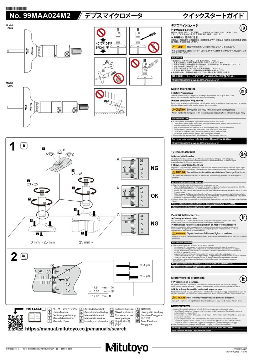
DepthMicrometer
User's ManualNo.99MAA024A
Contents
1. Names of Components ........................................................................................... Page 1
2. Precautions for Use................................................................................................. Page 1
3. Reference Point Setting .......................................................................................... Page 1
4. Changing the Measurement Range ........................................................................ Page 2
5. How to Read Graduations....................................................................................... Page 2
6. Specications.......................................................................................................... Page 2
7. Paid Maintenance ................................................................................................... Page 2
1. NamesofComponents
■
128Series
DMS
④ ⑤
③②①
⑦
⑥
NG
OK
NG
Reference line
Sleeve
Thimble
For 0 to 25 mm measurement range
For measurement range greater than 25 mm
2
Thimble
Ratchet stop
Key wrench
Rotate about three to ve times
Base
Reference surface
Precision surface plate
en
2Date of publication: May 1, 2023
Printed in Japan
Mitutoyo Corporation 20-1, Sakado 1-Chome, Takatsu-ku, Kawasaki-shi, Kanagawa
213-8533, Japan
●129Series
• If the reference point difference is ±0.01 mm or less
1 With the reference point conrmed, x the rod with the spindle clamp.
2Insert the supplied key wrench into the hole on the rear of the reference line on the sleeve, and then rotate the
sleeve until the reference line is aligned with the zero graduation line on the thimble.
• If the reference point difference is approximately ±0.01 mm or more
1 With the reference point conrmed, x the rod with the spindle
clamp.
2 Remove the thimble cap while holding it in place with your ngers
to prevent the thimble from rotating.
3Insert the supplied key wrench into the hole on the side of the
thimble xing nut and loosen the thimble xing nut.
4Rotate the thimble while pushing it toward the ratchet stop and
align the thimble's gradations with the sleeve's reference line.
5 Tighten the thimble xing nut with the key wrench while gently
pushing the thimble in the direction of the sleeve, being careful not
to allow the thimble to rotate.
6Mount the thimble cap and loosen the spindle clamp.
• Rod reference point adjustment
Important
• Dust and other debris adhering to the area where the rod collar contacts the rod end face can cause a reference
point error.
• Check the reference point again after temperature conditioning.
• If the rod is held in the hand for a long period of time during adjustment, the rod will expand, making accurate
reference point adjustment impossible. Please be careful.
• Be sure to adjust the reference point also when the rod is replaced.
• Set the rod into the body slowly. Setting the rod by dropping it rapidly can cause damage.
Although the rods are pre-adjusted for the reference point at the time of shipment, determine if the rod's reference point
needs to be adjusted after checking the reference point following the procedure below.
1 Mount the 0 to 25 mm rod and adjust the reference point of the Depth Micrometer body according to the method
described in "● If the reference point difference is ±0.01 mm or less" or "● If the reference point difference is
approximately ±0.01 mm or more."
2Replace the rod with one in the measurement range to be used and perform "■ Reference Point Conrmation".
3 If there is a reference point difference, adjust the reference point of the rod in accordance with the following
procedure.
• If the reference point difference is positive
1 Hold the thimble steady with your ngers and remove the thimble cap.
2Pull out the mounted rod.
3Insert the supplied key wrench into the hole on the side of the rod
collar and the supplied wrench into the tightening nut respectively.
4Loosen the tightening nut about half a turn in the direction of arrow.
5 Loosen the rod collar set screws (x2) with the supplied hex wrench.
6Move the rod collar to the end face of the tightening nut and lightly
tighten the set screw.
7Insert the supplied key wrench into the hole on the side of the rod
collar and the supplied wrench into the tightening nut respectively.
8Tighten the tightening nut in the direction of arrow.
8
7
7
Key wrench
Tightening nut
Rod collar
Wrench
5
6
Hex wrench
Set screw
Tightening nut
Rod collar
9 Tighten the rod collar set screws (x2) securely.
10 Insert the rod into the body and tighten the thimble cap securely.
11 Check the reference point again, and if further reference point adjustment is required, repeat steps 1- 10
above.
• If the reference point difference is negative
1
Hold the thimble steady with your ngers and remove the thimble cap.
2Pull out the mounted rod.
3
Loosen the rod collar set screws (x2) with the supplied hex wrench.
4Insert the supplied key wrench into the hole on the side of the rod
collar and the supplied wrench into the tightening nut respectively.
5Tighten the tightening nut in the direction of arrow.
» The rod collar moves in the direction of the arrow (Measurement
error amount moves).
6Perform steps 7to 9of "• If the reference point difference is
positive".
7Check the reference point again, and if further reference point
adjustment is required, repeat steps 1- 6above.
4. ChangingtheMeasurementRange
■129Series(128SeriesCannotChangetheMeasurementRange)
Important
• Set the rod into the body slowly. Setting the rod by dropping it rapidly can cause damage.
• Insert the rod carefully until it protrudes from the base.
1 Hold the thimble steady with your ngers and remove the thimble cap.
2Pull out the mounted rod and insert the appropriate rod.
3 Hold the thimble steady with your ngers and mount the thimble cap securely.
5. HowtoReadGraduations
Read the graduations as below.
① Sleeve (outer sleeve) reading 17.5 mm
②Thimble reading   0.37 mm
17.87 mm
Read the thimble at the location where the sleeve reference line matches the graduation line on the thimble.
This is normally read down to 0.01 mm as shown above,
but as shown in the gure below, it can also read by eye down to 0.001 mm.
Sleeve reference line Thimble graduation line Sleeve reference line Thimble graduation line
Approx. -1 µm Approx. -2 µm
6. Specications
• Maximum permissible measurement error : ±3 µm (±0.00015 in) (128 Series)
• Graduation : 0.01 mm (0.001 in)
• Operating temperature : 5 °C to 40 °C
• Storage temperature : -10 °C to 60 °C
5
6
4
4
Key wrench
Tightening nut
Rod collar
Wrench
①
②
7. PaidMaintenance
We recommend periodic inspections to check and maintain the product's accuracy. Also, if any of the following defects
occur, please contact the agent where you purchased the product or a Mitutoyo sales ofce.
・
Inconsistent measured values
Burrs or nicks generated by an impact on the measurement surfaces may affect measurement repeatability.
3
4
3
Key wrench
Rod collar
Tightening nut
Wrench
2
3
Thimble xing nut
Thimble cap
Thimble
Key wrench

This manual suits for next models

1

Other Mitutoyo Measuring Instrument manuals

Mitutoyo 99MAB034A1 User manual

Mitutoyo

Mitutoyo 99MAB034A1 User manual

Mitutoyo IT-012U User manual

Mitutoyo

Mitutoyo IT-012U User manual

Mitutoyo ID-CNX Series User manual

Mitutoyo

Mitutoyo ID-CNX Series User manual

Mitutoyo 500-150-30 User manual

Mitutoyo

Mitutoyo 500-150-30 User manual

Mitutoyo LGF-110ZL-B User manual

Mitutoyo

Mitutoyo LGF-110ZL-B User manual

Mitutoyo EJ-102N User manual

Mitutoyo

Mitutoyo EJ-102N User manual

Mitutoyo BA9700 User manual

Mitutoyo

Mitutoyo BA9700 User manual

Mitutoyo QuantuMike MDE-MX User manual

Mitutoyo

Mitutoyo QuantuMike MDE-MX User manual

Mitutoyo 209 Series User manual

Mitutoyo

Mitutoyo 209 Series User manual

Mitutoyo D/E User manual

Mitutoyo

Mitutoyo D/E User manual

Mitutoyo CONTRACER CV-2100 User manual

Mitutoyo

Mitutoyo CONTRACER CV-2100 User manual

Mitutoyo TI-1XX User manual

Mitutoyo

Mitutoyo TI-1XX User manual

Mitutoyo Digimatic MDC-S User manual

Mitutoyo

Mitutoyo Digimatic MDC-S User manual

Mitutoyo LGH Series User manual

Mitutoyo

Mitutoyo LGH Series User manual

Mitutoyo ID-N User manual

Mitutoyo

Mitutoyo ID-N User manual

Mitutoyo ID-SX User manual

Mitutoyo

Mitutoyo ID-SX User manual

Mitutoyo ID-F125 User manual

Mitutoyo

Mitutoyo ID-F125 User manual

Mitutoyo 700 Series User manual

Mitutoyo

Mitutoyo 700 Series User manual

Mitutoyo ID-C Series User manual

Mitutoyo

Mitutoyo ID-C Series User manual

Mitutoyo ID-C User manual

Mitutoyo

Mitutoyo ID-C User manual

Mitutoyo IMZ-MJ User manual

Mitutoyo

Mitutoyo IMZ-MJ User manual

Mitutoyo ID-N User manual

Mitutoyo

Mitutoyo ID-N User manual

Mitutoyo ID-C X series Service manual

Mitutoyo

Mitutoyo ID-C X series Service manual

Mitutoyo HDM-30AX User manual

Mitutoyo

Mitutoyo HDM-30AX User manual

Popular Measuring Instrument manuals by other brands

Master Meter Allegro installation guide

Master Meter

Master Meter Allegro installation guide

TESTO 816-1 instruction manual

TESTO

TESTO 816-1 instruction manual

ACS contsys DAL-311x3x0S operating instructions

ACS contsys

ACS contsys DAL-311x3x0S operating instructions

Sherwood Scientific CHROMA M260 Operator's manual

Sherwood Scientific

Sherwood Scientific CHROMA M260 Operator's manual

SICK InspectorP61x operating instructions

SICK

SICK InspectorP61x operating instructions

Fluke 985 user manual

Fluke

Fluke 985 user manual

PSI PlantPen/N-Pen N 110 Instruction guide

PSI

PSI PlantPen/N-Pen N 110 Instruction guide

Skil 0580 Original instructions

Skil

Skil 0580 Original instructions

Multiplex MX8120 operating instructions

Multiplex

Multiplex MX8120 operating instructions

BANTE Bante210 instruction manual

BANTE

BANTE Bante210 instruction manual

Geo Duet II user manual

Geo

Geo Duet II user manual

PCE Instruments PCE-HFX 100 user manual

PCE Instruments

PCE Instruments PCE-HFX 100 user manual

Extech Instruments PH220A user guide

Extech Instruments

Extech Instruments PH220A user guide

Keithley 595 instruction manual

Keithley

Keithley 595 instruction manual

wtw photoLab 6100 VIS manual

wtw

wtw photoLab 6100 VIS manual

Rosemount 1199 Reference manual

Rosemount

Rosemount 1199 Reference manual

HBK MP55 operating manual

HBK

HBK MP55 operating manual

NIREOS GEMINI 2D Installation and user technical manual

NIREOS

NIREOS GEMINI 2D Installation and user technical manual

manuals.online logo
manuals.online logoBrands
  • About & Mission
  • Contact us
  • Privacy Policy
  • Terms and Conditions

Copyright 2025 Manuals.Online. All Rights Reserved.