Cisco Catalyst 7500 Series User manual

1
Doc. No.
Copyright © 1996
Cisco Systems, Inc.
All rights reserved.
Replacing the Chassis Interface (CI) Board
in the Cisco 7500 Series Chassis
78-1810-02
Product Number: MAS-7500CI=
This document contains instructions for replacing the chassis interface (CI) board in the Cisco 7500
series routers: Cisco 7505, Cisco 7507, and Cisco 7513. The CI mounts directly to the front side of
the backplane inside each chassis and provides the environmental monitoring (ENVM) and power
supply monitoring functions for the Cisco 7500 series routers. The CI isolates the CPU and system
software from chassis-specific variations. The CI attaches directly to the system backplane and is
considered to be a field-replaceable unit (FRU).
Following are the functions of the CI:
•Reports backplane type
•Reports arbiter type
•Monitors power supply status
•Monitors fan/blower status
•Monitors temperature sensors on the RSP1
•Provides router power up/down control
•Provides power supply power-down control
•Provides temperature output for fan speed control
•Monitors power supply currents
Warning Before working on a system that has an on/off switch, turn OFF the power and unplug
the power cord. (For a translation of this safety warning, refer to the section “Translated Safety
Warnings” on page 32.)
To prevent injury, you must turn off all system power before opening the chassis to access the CI.
The system backplane, which is exposed when the front panels are removed, carries dangerous
current levels. Opening the chassis exposes the power distribution wiring on the backplane. If the
power is not shut down, the high current present on the backplane becomes a hazard. Also, removing
the cover compromises the electromagnetic interference (EMI) integrity of the system. Before
opening the chassis, read the section “Safety Guidelines” on page 2.

2Replacing the Chassis Interface (CI) Board in the Cisco 7500 Series Chassis
Document Contents and Structure
Note The CI is a FRU for the Cisco 7500 series chassis; therefore, we recommend that the
following procedures be performed by Cisco-certified service personnel.
Document Contents and Structure
Following is the recommended order in which to use the information and procedures included in this
publication:
1Before you begin the installation, review the information in the section “Installation
Prerequisites,” which follows.
2To install the CI in your chassis, refer to one of the following three sections for the specific
replacement procedure(s) for your chassis type(s).
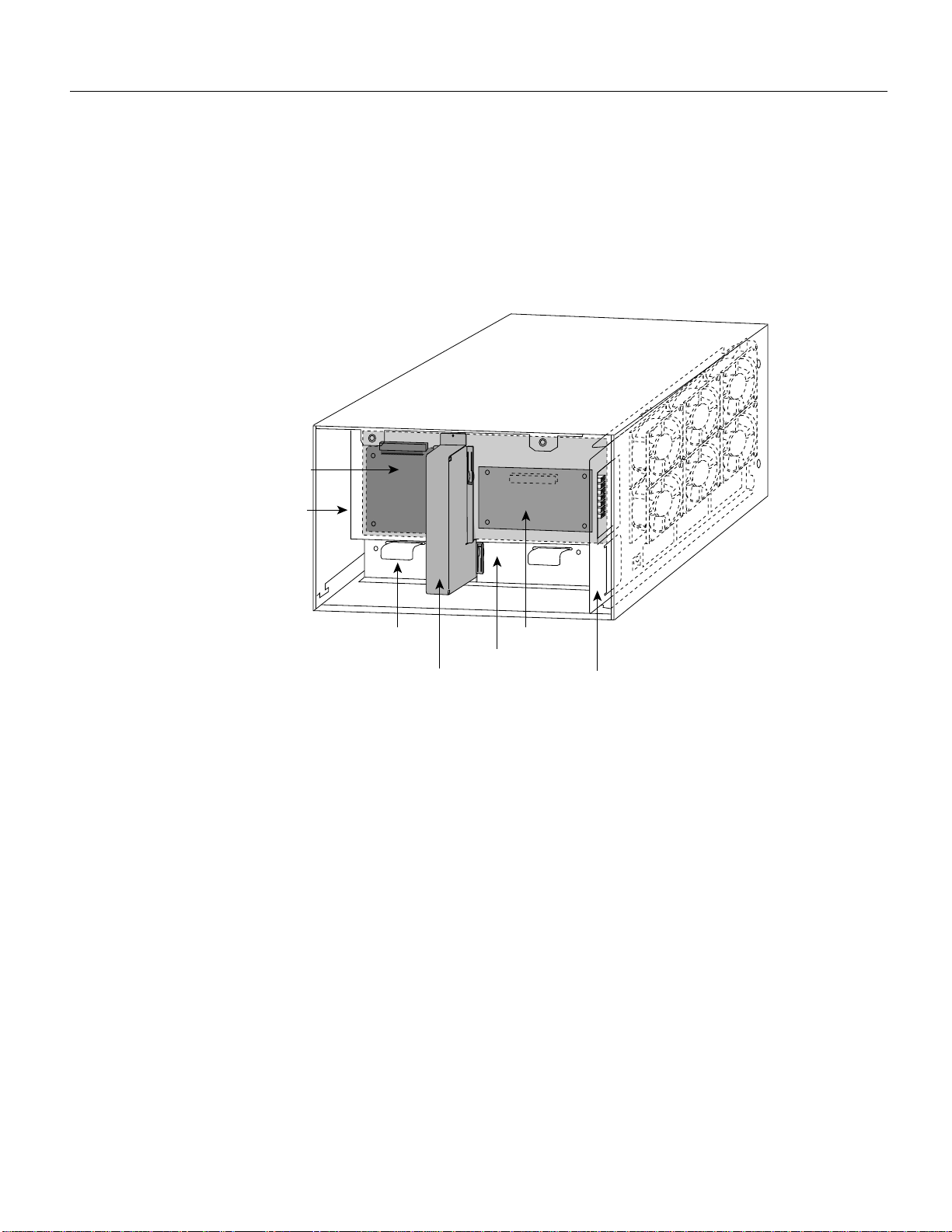
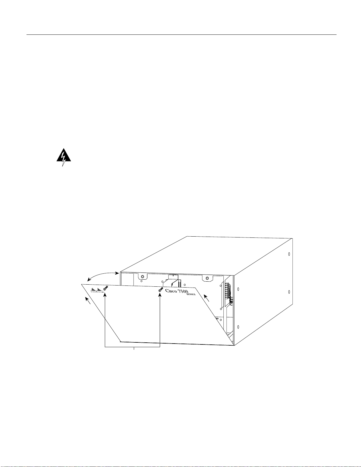
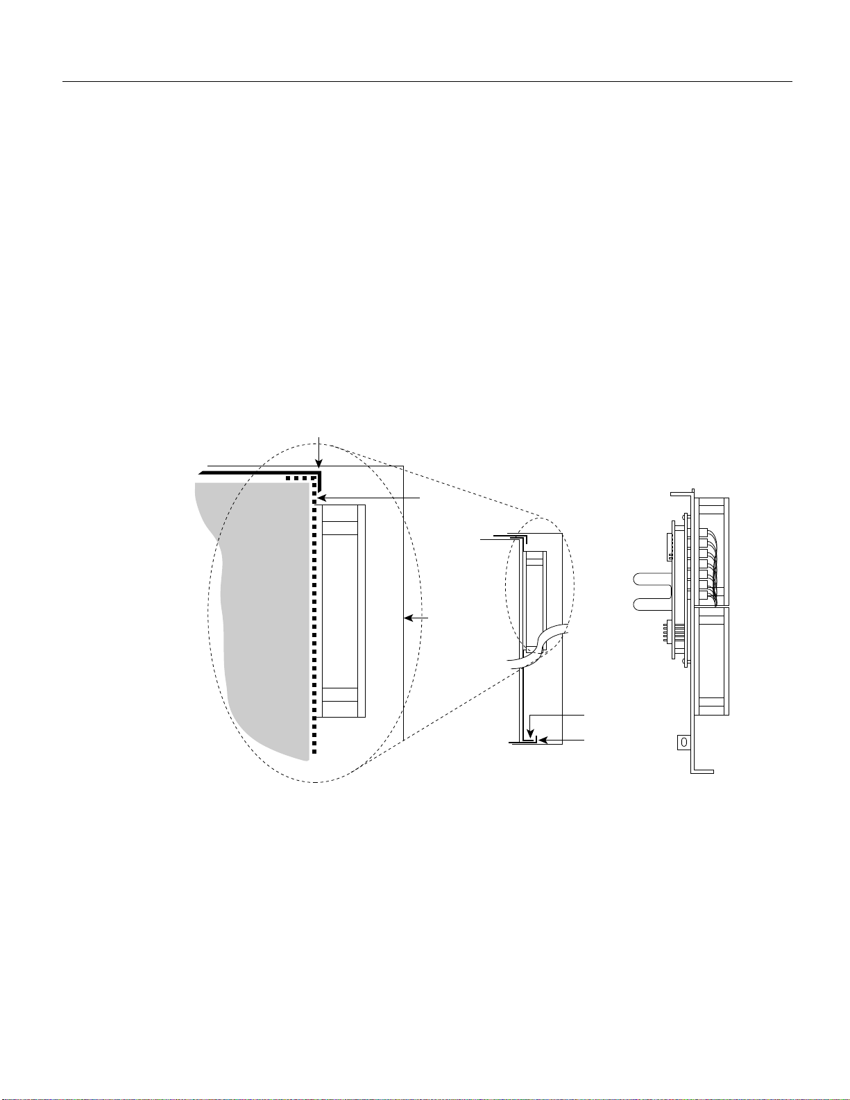
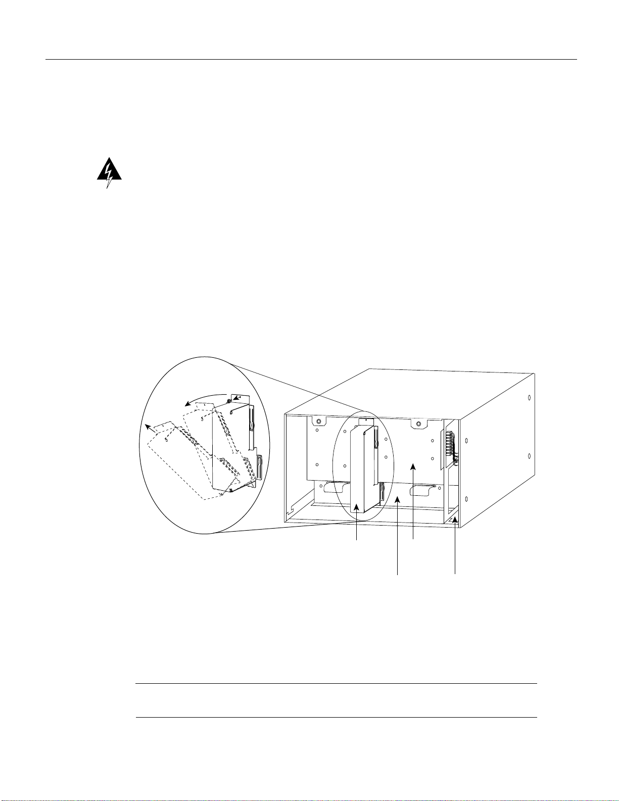
— Replacing the CI in the Cisco 7505, page 5
— Replacing the CI in the Cisco 7507, page 15
— Replacing the CI in the Cisco 7513, page 22
3To verify that the installation was successful, refer to the section “Checking the CI Installation”
on page 29.
4The following two sections contain important safety warning and reference information
respectively; refer to them as required and suggested:
— Translated Safety Warnings, page 32
— Cisco Connection Online, page 39
Installation Prerequisites
The following sections discuss important installation prerequisites.
Safety Guidelines
This section lists safety guidelines you should follow when working with any equipment that
connects to electrical power or telephone wiring.
Warning Read the installation instructions before you connect the system to its power source. (For
a translation of this safety warning, refer to the section “Translated Safety Warnings” on page 32.)
Electrical Equipment Guidelines
Follow these basic guidelines when working with any electrical equipment:
•Before beginning any procedures requiring access to the chassis interior, locate the emergency
power-off switch for the room in which you are working.
•Disconnect all power and external cables before moving a chassis.
Warning Before working on a system that has an on/off switch, turn OFF the power and unplug
the power cord. (For a translation of this safety warning, refer to the section “Translated Safety
Warnings” on page 32.)

Replacing the Chassis Interface (CI) Board in the Cisco 7500 Series Chassis 3
Installation Prerequisites
Warning Before working on a chassis or working near power supplies, unplug the power cord on
AC units; disconnect the power at the circuit breaker on DC units. (For a translation of this safety
warning, refer to the section “Translated Safety Warnings” on page 32.)
Warning Do not touch the power supply when the power cord is connected. For systems with a
power switch, line voltages are present within the power supply even when the power switch is off
and the power cord is connected. For systems without a power switch, line voltages are present
within the power supply when the power cord is connected. (For a translation of this safety warning,
refer to the section “Translated Safety Warnings” on page 32.)
Warning This unit might have more than one power cord. To reduce the risk of electric shock,
disconnect the two power supply cords before servicing the unit. (For a translation of this safety
warning, refer to the section “Translated Safety Warnings” on page 32.)
Note The following warning is for units with DC-input power supplies.
Warning Before performing any of the following procedures, ensure that power is removed from
the DC circuit. To ensure that all power is OFF, locate the circuit breaker on the panel board that
services the DC circuit, switch the circuit breaker to the OFF position, and tape the switch handle of
the circuit breaker in the OFF position. (For a translation of this safety warning, refer to the section
“Translated Safety Warnings” on page 32.)
•Do not work alone if potentially hazardous conditions exist.
•Never assume that power is disconnected from a circuit; always check.
•Do not perform any action that creates a potential hazard to people or makes the equipment
unsafe.
•Carefully examine your work area for possible hazards such as moist floors, ungrounded power
extension cables, and missing safety grounds.
Telephone Wiring Guidelines
Use the following guidelines when working with any equipment that is connected to telephone
wiring or to other network cabling:
•Never install telephone wiring during a lightning storm.
Warning Do not work on the system or connect or disconnect cables during periods of lightning
activity. (For a translation of this safety warning, refer to the section “Translated Safety Warnings”
on page 32.)
•Never install telephone jacks in wet locations unless the jack is specifically designed for wet
locations.
•Never touch uninsulated telephone wires or terminals unless the telephone line has been
disconnected at the network interface; use caution when installing or modifying telephone lines.

4Replacing the Chassis Interface (CI) Board in the Cisco 7500 Series Chassis
Installation Prerequisites
Warning Before opening the chassis, disconnect the telephone-network cables to avoid contact
with telephone-network voltages. (For a translation of this safety warning, refer to the section
“Translated Safety Warnings” on page 32.)
Preventing Electrostatic Discharge Damage
Electrostatic discharge (ESD) damage, which can occur when electronic cards or components are
improperly handled, results in complete or intermittent failures. Following are guidelines for
preventing ESD damage:
•Always use an ESD-preventive wrist or ankle strap and ensure that it makes good skin contact.
•Connect the equipment end of the strap to a captive installation screw on an installed power
supply.
•Handle the CI by the edges only; avoid touching the board or connector.
•Place a removed CI board-side-up on an antistatic surface or in a static shielding bag. If the
component will be returned to the factory, immediately place it in a static shielding bag.
•Avoid contact between the CI and clothing. The wrist strap only protects the board from ESD
voltages on the body; ESD voltages on clothing can still cause damage.
Caution Forsafety, periodically check the resistance value of the antistatic strap. The measurement
should be between 1 and 10 megohms.
List of Parts and Tools
Following are the tools and equipment that you will need to complete the CI replacement:
•ESD-preventive equipment (a disposable wrist strap is included with all spares and upgrade kits)
•Antistatic mat, foam pad, or bag for the removed CI (immediately place a removed board into an
antistatic bag if you will return it to the factory)
•3/16-inch, flat-blade screwdriver; Number 1 and Number 2 Phillips screwdrivers
•CI board for your Cisco 7500 series chassis (MAS-7500CI=)

Replacing the Chassis Interface (CI) Board in the Cisco 7500 Series Chassis 5
Replacing the CI in the Cisco 7505
The following procedures describe how to replace the CI in the Cisco 7505. Depending on your
installation, you might need to remove the Cisco 7505 from the rack in which it is installed. Figure 1
shows the interior of the Cisco 7505 at the front (noninterface processor end) of the chassis, with the
front chassis panel removed to show the internal components.
Figure 1 Internal Chassis Components
Overview of the CI Replacement in the Cisco 7505
In the Cisco 7505, the CI mounts directly to the noninterface processor side of the backplane, behind
the backplane cover. (See Figure 1.) A connector on the back of the CI plugs into a backplane socket,
and the corners of the CI butt up against four standoffs. When the backplane cover is in place, four
long Phillips screws extend through the cover, the CI, and standoffs to secure the cover and the CI
to the backplane. To replace the CI, you must remove the chassis cover panel and remove the fan
tray, power harness cover, and backplane cover.
You must remove the fan tray in order to remove the backplane cover. To remove the fan tray, you
need only remove a single M4 pan-head screw that anchors the fan tray to the interior chassis frame.
The fan tray slides into the right side of the chassis (when viewing the chassis from the noninterface
processor end).
Because the power harness cover straddles both the power supply and backplane cover, you must
remove it to access the CI. The power harness cover shields the wiring harness that delivers DC
power from the power supply to the backplane. A tab at the bottom of the cover fits into a slot in the
chassis floor; a single Phillips screw secures the top of the harness cover to the backplane cover.
The backplane cover shields the noninterface processor side of the backplane and the CI (the CI
cover is integrated with the backplane cover). Fourteen Phillips screws secure the four flanged sides
of the cover to the interior chassis frame and, near the center of the cover, two additional screws
secure the cover to two standoffs mounted to the backplane (behind the cover).
Power harness
cover
Arbiter
Power supply Fan tray
H2864
Power supply
handles
Chassis interface
Backplane cover

6Replacing the Chassis Interface (CI) Board in the Cisco 7500 Series Chassis
Replacing the CI in the Cisco 7505
The CI standoff screws secure the backplane cover and the CI to the four CI standoffs mounted to
the backplane. Removing the backplane cover exposes the entire backplane, including the CI, which
remains attached to the backplane by the 96-pin connector.
Removing and Replacing the Chassis Cover Panel
The two captive slotted screws are the only fasteners on the cover panel. Five shallow tabs at the
bottom edge of the panel fit into slots at the base of the chassis opening. The tabs act as a pivot point
for pulling the top of the panel away from the chassis opening, and as guides to align the panel when
replacing it. If the chassis cover does not seal the end of the chassis, the flow of cooling air inside
the chassis can be misrouted, which can result in an overtemperature condition.
Warning Before working on a system that has an on/off switch, turn OFF the power and unplug
the power cord. (For a translation of this safety warning, refer to the section “Translated Safety
Warnings” on page 32.)
Follow these steps to remove and replace the chassis cover panel:
Step 1 Use a 3/16-inch flat-blade screwdriver to loosen the two captive screws on the front of the
cover panel. (See Figure 2.)
Figure 2 Removing and Replacing the Chassis Cover Panel
Step 2 Pull the top of the panel out about three inches (see Figure 2), then grasp the sides of the
panel and pull it upward and away from the chassis.
Step 3 To replace the cover panel, hold the sides of the panel with both hands and tilt the top of
the panel back slightly (toward you).
Step 4 Slide the guide tabs into the slots into the bottom edge of the chassis.
Step 5 Using the guides as a pivot point, push the top half of the panel back toward the chassis
opening until the panel is flush with the edges of the chassis.
H2869
Captive screws

Replacing the Chassis Interface (CI) Board in the Cisco 7500 Series Chassis 7
Replacing the CI in the Cisco 7505
Step 6 Hold the top front of the panel in place, if necessary, while you tighten the two captive
slotted screws with a 3/16-inch flat-blade screwdriver.
This completes the chassis cover panel removal and replacement procedure.
Removing and Replacing the Fan Tray
When viewing the chassis from the noninterface processor end, the fan tray is on the far right. (See
Figure 3.) A cutout in the front of the tray provides a handle for pulling the tray out of the chassis.
An M4 Phillips-head screw anchors a tab on the lower left side of the tray to the interior chassis
frame, just below the right power supply ear. When the fan tray is fully inserted in the chassis, an
edge connector on the fan control board snaps into the backplane electrical connector. The bottom
of the tray is a metal runner that guides the tray along a metal track on the chassis floor. Also, a
bracket on the chassis ceiling helps guide the tray into the chassis.
Follow these steps to replace the fan tray:
Step 1 Turn OFF the system power switch and unplug the power cable from the power source.
Step 2 To remove the chassis cover panel, follow Steps 1 and 2 in the section “Removing and
Replacing the Chassis Cover Panel” on page 6.
Step 3 Attach an ESD-preventive strap between you and an unpainted surface on the chassis.
Step 4 Locate the fan tray, which is in the far right of the noninterface processor end of the chassis.
(See Figure 3.) On the lower left side of the fan tray, locate the tab that is anchored to the
chassis frame with an M4 Phillips screw.
Step 5 Use a number 2 Phillips screwdriver to remove the M4 Phillips screw from the tab on the
fan tray. (See the cutaway view of this screw in Figure 3.)
Step 6 Grasp the cutout handle in the front of the tray and pull the fan tray straight out of the
chassis. (See Figure 3.) After the fan control board connector frees the backplane socket,
the fan tray will slide easily along the track and out of the chassis.
Step 7 Place the removed fan tray in an antistatic bag for storage or return to the factory.

8Replacing the Chassis Interface (CI) Board in the Cisco 7500 Series Chassis
Replacing the CI in the Cisco 7505
Step 8 Hold the assembly in the position shown in Figure 3. You can hold the handle with either
your right or left hand as long as you use both hands to handle the tray. However, when
inserting the tray, there is little room between the tray and the right side of the chassis. Keep
the tray as straight as possible, or you may have trouble inserting it into the chassis.
Figure 3 Replacing the Fan Tray
Note Before inserting the fan tray, compare the hardware inside the chassis to that shown in
Figure 4. The runner on the bottom of the fan tray has to slide along in the track on the floor. At the
same time, the runner on the top of the tray has to slide through the notch at the top of the chassis
opening, then over the top of the card cage while staying to the left of the L-bracket on the chassis
ceiling.
Removing/replacing
fan tray
H2865

Replacing the Chassis Interface (CI) Board in the Cisco 7500 Series Chassis 9
Replacing the CI in the Cisco 7505
Step 9 Insert the top runner of the fan tray through the notch in the top of the chassis. Continue
pushing the tray into the chassis, and ensure that the bottom runner slides into the track on
the floor of the chassis. If the tray hangs up, pull it back out a few inches and try pushing it
back in again. If the runners seem to be catching on the brackets, push the tray slightly
toward the left when inserting it again.
Step 10 Slide the tray back into the chassis, pushing it all the way in until the circuit board snaps
into the backplane socket.
Step 11 Replace the M4 screw in the tab and tighten it with a number 2 Phillips screwdriver. (See
the cutaway view of this screw in Figure 3, on page 8.)
Step 12 To replace the cover panel, follow Steps 3 through 6 in the section “Removing and
Replacing the Chassis Cover Panel” on page 6.
This completes the fan tray replacement.
Figure 4 Fan Tray Tracks and Guides
L-bracket
Track
Bottom runner
Chassis
enclosure
Fan tray,
side view
H2870
Fan tray,
side view
Card cage

10 Replacing the Chassis Interface (CI) Board in the Cisco 7500 Series Chassis
Replacing the CI in the Cisco 7505
Removing and Replacing the Power Harness Cover and Power Harness
You must remove the power harness cover to access either the power supply or the CI. A single M-3
Phillips screw secures the power harness cover to the backplane cover.
Warning Before working on a system that has an on/off switch, turn OFF the power and unplug
the power cord. (For a translation of this safety warning, refer to the section “Translated Safety
Warnings” on page 32.)
Follow these steps to remove and replace the power harness cover:
Step 1 Turn OFF the system power switch and unplug the power cable from the power source.
Step 2 To remove the chassis cover panel, follow Steps 1 and 2 in the section “Removing and
Replacing the Chassis Cover Panel” on page 6.
Step 3 Use a number 1 Phillips screwdriver to remove the M-3 screw that secures the top of the
harness cover to the backplane. (See the cutaway in Figure 5.)
Figure 5 Removing the Power Harness Cover
Step 4 Holding the cover with one hand, tilt the top of the cover back toward you, then pull it
upward slightly so that the tab clears the slot in the chassis floor.
Step 5 When the tab clears the slot, pull the cover straight back off the harness and out of the
chassis.
Note Move on to the required procedure, depending on the work you need to do. Then to replace
the power harness and power harness cover, proceed to Step 6, which follows.
Power harness
cover Arbiter/chassis
interface board
cover
Power supply Fan tray
Removing power harness cover
H2867

Replacing the Chassis Interface (CI) Board in the Cisco 7500 Series Chassis 11
Replacing the CI in the Cisco 7505
Step 6 To replace the power harness cover, hold the cover with one hand, with the tab on the
bottom and the open side facing away from you. Tilt the top of the panel back slightly
(toward you).
Step 7 Insert the tab on the bottom of the cover into the slot in the chassis floor. (See Figure 5.)
Step 8 While pushing the cover downward slightly to keep the bottom tab in the slot, push the top
of the cover back over the harness wires until the sides are flush against the backplane
cover. Ensure that all of the harness wires are under the cover.
Step 9 Insert the M-3 screw through the top of the harness cover, and use a number 1 Phillips
screwdriver to tighten it. (See the cutaway in Figure 5.)
Step 10 To replace the cover panel, follow Steps 3 through 6 in the section “Removing and
Replacing the Chassis Cover Panel” on page 6.
This completes the power harness cover removal and replacement procedures.
Removing and Replacing the Backplane Cover
The backplane cover provides EMI and ground protection for the backplane, the arbiter, and the CI.
To access these components, you must remove the backplane cover. You need number 1 and
number 2 Phillips screwdrivers to remove the backplane cover screws. Following is the procedure
for removing and replacing the backplane cover.
Note This procedure assumes that you have already removed the chassis cover panel, the fan tray,
the power harness cover, and the power harness. If not, refer to the appropriate sections in this
publication to remove these items.
Step 1 Attach an ESD-preventive strap between you and an unpainted chassis surface.
Step 2 With the fan tray removed, remove the eight, 20-mm M-3 standoff screws that secure the
backplane cover to the arbiter and CI standoffs. These screws are located on the face of the
backplane cover. (See Figure 6.)

12 Replacing the Chassis Interface (CI) Board in the Cisco 7500 Series Chassis
Replacing the CI in the Cisco 7505
Figure 6 Removing and Replacing the Backplane Cover
Step 3 Remove the fifteen, 10-mm M-3 Phillips that secure the backplane cover to the backplane.
These screws are located around the flange of the backplane cover (two on each side, six
along the top, and five along the bottom). (See Figure 6.)
Caution To prevent loosening the backplane from the chassis, remove only those screws that
secure the backplane cover to the backplane. Do not remove any adjacent screws.
Step 4 With all screws removed, carefully guide the backplane cover out and away from the
backplane, arbiter, and CI. (See Figure 6.)
Note Depending on the replacement procedures you need to perform, refer to the appropriate
sections, and then to replace the backplane cover, proceed to Step 5, which follows.
Step 5 To replace the backplane cover, carefully guide the cover into the chassis opening over the
arbiter and CI, over the guide pins on the backplane (see Figure 6), and align the screw
holes in the cover with the holes on the backplane and standoffs.
Step 6 Loosely install the fifteen screws around the flange of the backplane cover. (See Figure 6.)
Do not tighten these screws.
H2872
Six 10-mm M-3 screws on top, five on bottom
Two 10-mm
M-3 screws
each side
Four 20-mm
M-3 screws
Four 20-mm M-3 screws
Guide pin
hole
Guide pin
hole

Replacing the Chassis Interface (CI) Board in the Cisco 7500 Series Chassis 13
Replacing the CI in the Cisco 7505
Step 7 Loosely install the eight standoff screws in the face of the backplane cover. (See Figure 6.)
Step 8 Verify that the cover is aligned; then tighten all screws that secure the backplane cover.
Step 9 To replace the fan tray, follow Steps 8 through 12 in the section “Removing and Replacing
the Fan Tray” on page 7.
Step 10 Reattach the power harness plug to the power harness receptacle. The harness plug and
backplane receptacle are polarized with notches at the top of both guide tabs (top and
bottom) on the plug. Ensure that the plug is fully seated in the receptacle.
Step 11 To replace the power harness cover, follow Steps 6 through 10 in the section “Removing
and Replacing the Power Harness Cover and Power Harness” on page 10.
Step 12 To replace the cover panel, follow Steps 3 through 6 in the section “Removing and
Replacing the Chassis Cover Panel” on page 6.
This completes the backplane cover removal and replacement procedure.
Removing and Replacing the CI
The CI (shown in Figure 7) is a printed circuit board mounted to the noninterface processor side of
the backplane, behind the backplane cover. On the back (backplane side) of the chassis are four
standoffs and a connector that plugs directly into the backplane. When the backplane cover is in
place, four standoff screws extend through the backplane cover, through each corner of the CI and
into the standoffs, to keep both the CI and backplane cover in place.
Figure 7 Chassis Interface (MAS-7500CI=)
Note Replace the CI only if it fails. This procedure assumes that you have already removed the
chassis cover panel, the fan tray, the power harness cover, the power harness, and the backplane
cover. If not, refer to the appropriate procedures in this section to remove these items.
H2877
Chassis interface
Standoff
screw holes Standoff
screw holes

14 Replacing the Chassis Interface (CI) Board in the Cisco 7500 Series Chassis
Replacing the CI in the Cisco 7505
Removing the CI Follow these steps to remove the CI:
Step 1 Turn OFF the system power switch and disconnect the power cable from the power source.
Step 2 Attach an ESD-preventive strap (your own or the one supplied with the FRU) between you
and an unpainted chassis surface.
Step 3 Because you already had to remove the CI standoff screws to remove the backplane cover,
the CI is held in place only by the connector that is connected to the backplane. Grasp the
edges of the CI and pull it straight out at a 90-degree orientation to the backplane to
disconnect the CI connector from the backplane socket. (See Figure 8.) If necessary, gently
rock the CI from side to side very slightly to dislodge the pins from the backplane
connector.
Step 4 Place the CI in an antistatic bag.
This completes the CI removal procedure.
Figure 8 Removing and Replacing the CI
Installing the New CI
When you replace the CI, hold it in the orientation shown in Figure 8, with the connector along the
top and facing the backplane. Position the board over the backplane connector and align the four
standoff holes in the corners of the board with the four standoffs.
Follow these steps to replace the CI:
Step 1 Attach an ESD-preventive strap (your own or the one supplied with the FRU) between you
and an unpainted chassis surface.
Step 2 Place your fingers around the top and side edges of the CI and push it straight in toward the
backplane until the connector is fully seated in the backplane socket and the standoff screw
holesintheCIarealignedwiththestandoffs. (See Figure 8.) Itmightbenecessarytogently
rock the connectors into place.
Step 3 Reconnect the power harness plug to the backplane receptacle; the plug and receptacle are
polarized with notches on the guide tabs. If you have trouble making the connection, ensure
that the notch is at the top on both guide tabs (top and bottom) on the plug.
Chassis
interface
standoffs (4)
H2874

Replacing the Chassis Interface (CI) Board in the Cisco 7500 Series Chassis 15
Replacing the CI in the Cisco 7507
Step 4 To replace the backplane cover, follow Steps 5 through 12 in the section “Removing and
Replacing the Backplane Cover” on page 11.
Step 5 To replace the power harness cover, follow Steps 6 through 10 in the section “Removing
and Replacing the Power Harness Cover and Power Harness” on page 10.
Step 6 To replace the fan tray, follow Steps 8 through 12 in the section “Removing and Replacing
the Fan Tray” on page 7.
Step 7 To replace the chassis cover panel, follow Steps 3 through 6 in the section “Removing and
Replacing the Chassis Cover Panel” on page 6.
This completes the CI replacement procedure for the Cisco 7505.
Replacing the CI in the Cisco 7507
The following procedures describe how to replace the CI in the Cisco 7507. Depending on your
installation, you might need to remove the Cisco 7507 from the rack in which it is installed. To
replace the CI in the Cisco 7507, you must first remove the front chassis panels.
Removing the Front Chassis Panels
You must remove the top and bottom front chassis panels to access the chassis interior to replace the
CI board.
Warning Before working on a system that has an on/off switch, turn OFF the power and unplug
the power cord. (For a translation of this safety warning, refer to the section “Translated Safety
Warnings” on page 32.)
You must remove the bottom front panel before you can remove the top front panel. The plastic
bottom front panel is attached to the chassis with ball studs. The top front panel is attached to the
chassis with two captive screws. The EMI shielding around the outer edge of the top front panel acts
as a spring, and compresses when you push the panel into the chassis to keep the panel fitted tightly
into the chassis opening.

16 Replacing the Chassis Interface (CI) Board in the Cisco 7500 Series Chassis
Replacing the CI in the Cisco 7507
To remove the front panels, perform the following steps:
Step 1 Grasp the bottom edge of the bottom chassis panel.
Step 2 Pull the bottom of the panel out about one inch, then place your fingers behind the sides of
the panel and pull it off the chassis. (See Figure 9.)
Figure 9 Removing the Bottom Front Panel
UPPER
POWER LOWER
POWER NORMAL
Cisco 7000
H1335a

Replacing the Chassis Interface (CI) Board in the Cisco 7500 Series Chassis 17
Replacing the CI in the Cisco 7507
Step 3 On the top front panel, use a screwdriver to loosen the two captive screws at the bottom
edge of the panel frame.
Step 4 Place one hand against the top front center of the panel to brace it. (See Figure 10a.) The
top of the panel acts as a pivot point when you pull the bottom out and away from the
chassis.
Figure 10 Removing the Top Front Panel
Step 5 With your other hand, grasp the front of the panel by inserting your fingers into the opening
on the underside of the bezel. (See Figure 10a.)
Step 6 While pushing slightly against the top of the panel to constrain it, pivot the bottom edge of
the frame outward about two inches. (See Figure 10a.) Because of the tightly compressed
EMI shielding, you will have to use significant force to pull the bottom of the panel
outward. However, be careful that you do not pull the panel more than two inches away
from the chassis, or you can damage the inner bezel or LED board.
Step 7 When the bottom of the frame clears the chassis opening, keep your hands in the same
positions and pull the panel downward and off the chassis. (See Figure 10b.)
With front chassis panels removed, the CI board is exposed to view.
Cisco 7000
UPPER
POWER LOWER
POWER NORMAL
Cisco 7000
UPPER
POWER LOWER
POWER NORMAL
H1459a
ab

18 Replacing the Chassis Interface (CI) Board in the Cisco 7500 Series Chassis
Replacing the CI in the Cisco 7507
Removing and Replacing the CI
The CI (shown in Figure 7) is a printed circuit board mounted to the noninterface processor side of
the backplane. On the back (backplane side) of the chassis is a connector into which the CI plugs
directly into the backplane.
Figure 11 Chassis Interface (MAS-7500CI=)
Note Replace the CI only if it fails. This procedure assumes that you have already removed the
front chassis panels. If not, refer to the appropriate procedures in this section to remove these items.
H2877
Chassis interface
Standoff
screw holes Standoff
screw holes

Replacing the Chassis Interface (CI) Board in the Cisco 7500 Series Chassis 19
Replacing the CI in the Cisco 7507
Removing the CI Follow these steps to remove the CI:
Step 1 Turn OFF the system power switch and disconnect the power cable from the power source.
Step 2 Attach an ESD-preventive strap (your own or the one supplied with the FRU) between you
and an unpainted chassis surface.
Step 3 Refer to Figure 12 and locate the CI board, which is mounted to the back of the backplane.
The CI is oriented vertically, attached to the backplane via the edge connector, and is
located to the right of the dual arbiter, as shown in Figure 12.
Figure 12 Location of the CI on the Cisco 7507 Backplane
Step 4 Carefully remove the CI from its backplane connector.
Step 5 Place the CI in an antistatic bag.
This completes the CI removal procedure.
H13884
LED board
(mounted on horizontal
plane in chassis)
LED board spring
LEDs
Dual arbiter
Blower power
connection
Blower air ducts to
interface processor
compartment
Chassis interface
(mounted on
vertical plane)

20 Replacing the Chassis Interface (CI) Board in the Cisco 7500 Series Chassis
Replacing the CI in the Cisco 7507
Installing the New CI
When you install the new CI, hold it in the vertical orientation shown in Figure 12, with the
connector along the edge of the CI facing the CI backplane connector. Both CI connectors are keyed
soyoucannotinstalltheCIincorrectly;however,topreventdamagetotheconnector pins, determine
the correct connection orientation before you install the CI.
Follow these steps to replace the CI:
Step 1 Attach an ESD-preventive strap (your own or the one supplied with the FRU) between you
and an unpainted chassis surface.
Step 2 Attach the CI’s connector to the CI connector on the backplane via the edge connector on
the CI board. If the edge connector’s keys are aligned, the CI should attach to the backplane
connector with a moderate amount of force. Do not force the CI into the CI connector onto
the backplane connector.
This completes the CI replacement procedure for the Cisco 7507.
Replacing the Front Chassis Panels
To replace the front panels, perform the following steps:
Step 1 Grasp the sides of the top panel with both hands. (See Figure 13a on page 21.)
Step 2 Two guide tabs at the top edges of the panel fit into two slots in the top edges of the chassis
opening. Tilt the top of the panel back (away from you) about 30 degrees from vertical and
slide the two guide tabs into the chassis slots. (See Figure 13a.)
Step 3 Check the top of the panel to make sure it is lined up with the top of the chassis opening.
Failure to align the panel at this point can result in equipment damage when performing the
next step.
Step 4 Push the panel upward to push the tabs into the slots (see Figure 13a) and pivot the bottom
of the panel toward the chassis until the panel frame meets the chassis. (See Figure 13b.)
Maintain a steady upward pressure to keep the guide tabs in the chassis slots.
Step 5 When the panel is flush against the front of the chassis, push the panel upward until the
bottom of the panel is level with the bottom of the chassis opening. (See Figure 13c.)
Step 6 While holding the panel in place, place one palm against the top front center of the panel
to brace it, and place the other against the lip near the bottom edge of the frame. (See
Figure 13d.)
Step 7 Push the panel upward and back into the chassis opening until the tabs on the front sides of
the panel are flush against the front of the chassis. (See Figure 13e.) You will have to use
significant force to compress the EMI shielding enough to fit into the opening. If the panel
resists, pull it slightly downward and make sure that the panel is lined up with the top and
sides of the opening in the chassis.
Step 8 When the tabs on the front sides of the panel are flush against the sides of the chassis,
tighten the two captive screws in the bottom edge of the frame.
Step 9 To replace the bottom front panel, place the ball studs on the back of the panel over the
holes in the front lip of the chassis and push the panel onto the chassis until the ball studs
snap into place.
This completes the CI replacement procedure for the Cisco 7507.
Other manuals for Catalyst 7500 Series
1
This manual suits for next models
1
Table of contents
Other Cisco Recording Equipment manuals

Cisco
Cisco CX-CIP2-ECA2 Series Operating and maintenance instructions

Cisco
Cisco WIC-2T User manual

Cisco
Cisco 4492R Original instructions

Cisco
Cisco VIC-2FXS User manual

Cisco
Cisco T1 Quick start guide

Cisco
Cisco 15310-EIA-HD-A Instruction Manual

Cisco
Cisco Flex 7500 Series User manual

Cisco
Cisco uBR10-MC5X20S User manual

Cisco
Cisco Linksys DMRW1000 User manual

Cisco
Cisco 2500 Series Quick reference guide