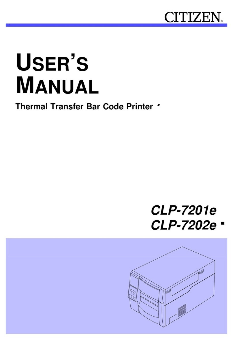
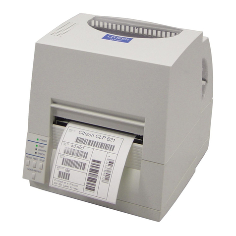
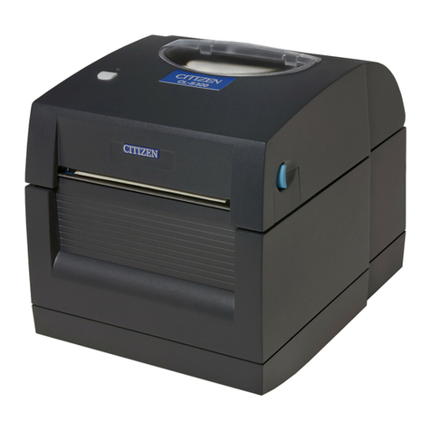
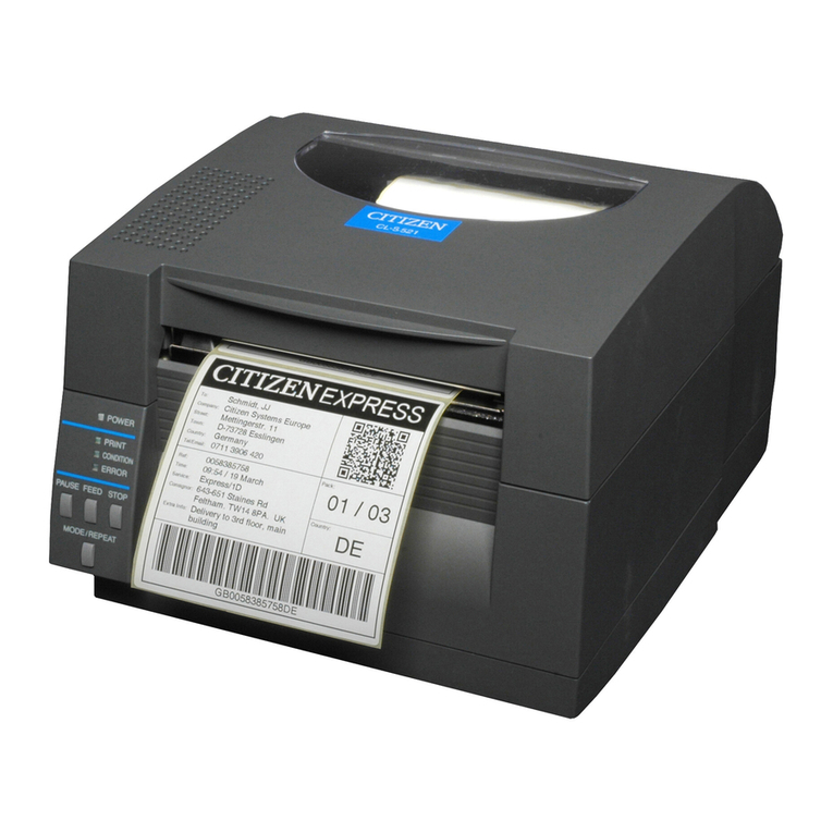
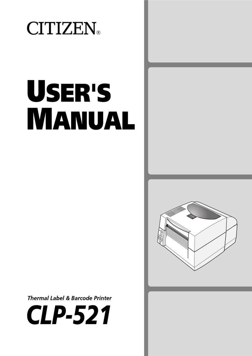
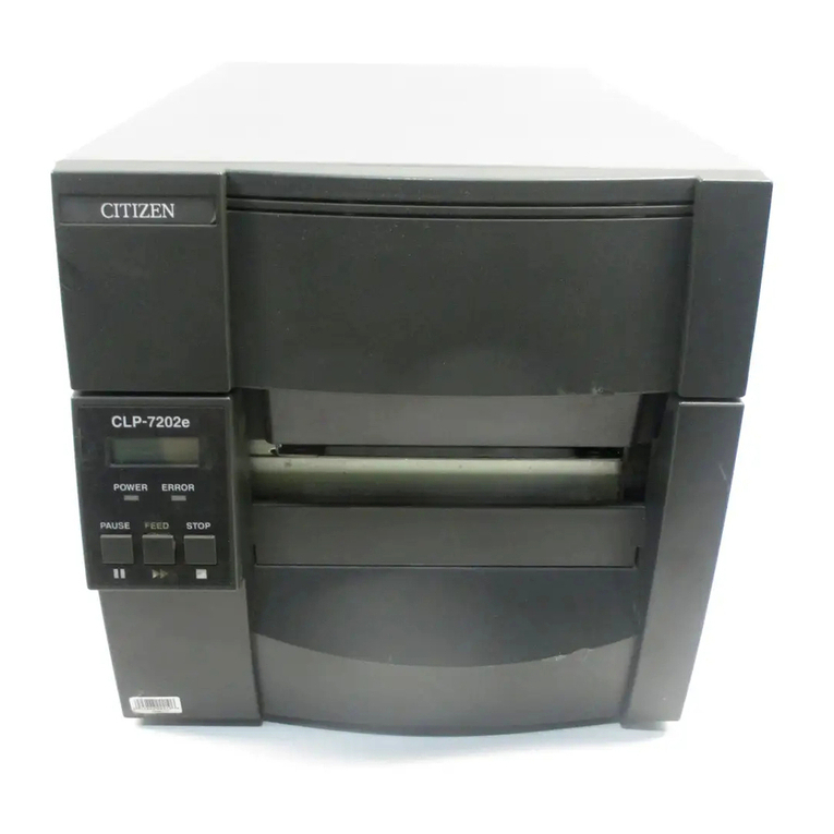
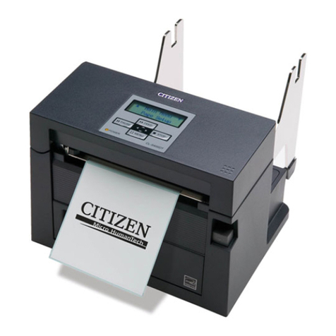
Citizen CLP 621 CLP-621 CLP-621 User manual

CLP-621 & CLP-631
Thermal Transfer Barcode & Label Printer
USER'S MANUAL

2
CONTENTS
Before Operation
INTRODUCTION -------------------------------------------------------------------- 3
COMPLIANCE STATEMENT FOR EUROPEAN USERS----------------------------- 4
FCC COMPLIANCE STATEMENT FOR AMERICAN USERS ----------------------- 4
EMI COMPLIANCE STATEMENT FOR CANADIAN USERS------------------------ 5
ETAT DE CONFORMITE EMI A L’USAGE DES UTILISATEURS CANADIENS ----- 5
IMPORTANT SAFETY INSTRUCTIONS--------------------------------------------- 6
NOTICE ------------------------------------------------------------------------------- 7
SAFETY INSTRUCTIONS ------------------------------------------------------------ 8
Chapter 1 Setup
Confi mation of Ca ton Contents -------------------------------------------------10
Pa t Names and Functions---------------------------------------------------------- 11
Connection to Powe ---------------------------------------------------------------17
D ive Installation -------------------------------------------------------------------17
Connection to a Compute --------------------------------------------------------18
Chapter 2 Printer Operation
Powe ON/OFF ----------------------------------------------------------------------19
No mal Ope ating Mode ---------------------------------------------------------- 20
Setting the Media ------------------------------------------------------------------ 22
Setting the Ribbon ----------------------------------------------------------------- 26
Mode Settings ---------------------------------------------------------------------- 29
Quick Setup of the P int Method ------------------------------------------------- 38
Chapter 3 Printer Adjustments
Senso Adjustments --------------------------------------------------------------- 39
Media Thickness Adjustment ----------------------------------------------------- 42
Media Width Adjustment ---------------------------------------------------------- 43
Adjusting the Ribbon -------------------------------------------------------------- 44
Cleaning ---------------------------------------------------------------------------- 46
Chapter 4 Troubleshootin ----------------------47
Appendixes
Specifications ---------------------------------------------------------------------- 49
Inte faces --------------------------------------------------------------------------- 52
Replacing the Inte face Boa d ---------------------------------------------------- 58

3
❚❚❚ Main Features ❚❚❚
<Hi h-speed, hi h-quality printin >
This p inte can be used fo high-speed high-quality p inting thanks to its di ect the mal method
and the mal t ansfe method that use a line the mal p inthead togethe with its 32 bit RISC CPU
and its 'histo y cont ol IC'.
<Easy operation>
• It is easy to change the p inte ’s settings on the ope ation panel, thanks to its unique and
simple VueP int menu system.
• Its high-lift p inthead and mechanism means that media and ibbon can be loaded with ease
and it is const ucted fo easy the mal p inthead cleaning, etc.
• Media width adjustment, media thickness adjustment, and media senso adjustment can all be
made easily by the use using the colou -coded ope ato cont ols.
<Interface>
A se ial po t, IEEE1284 pa allel po t (ECP mode) and USB a e standa d equipment, fo quick data
t ansfe and p inting.
<Optional interface>
The p inte s have optional inte nally housed netwo k inte faces.
<Optional auto-cutter / peeler unit>
The auto-cutte and peele units a e designed so that they can be installed easily.
<Adjustable sensors>
The adjustable media senso s - which allow the senso s to be positioned in diffe ent locations
ac oss the media - a e standa d featu es making the p inte ideal fo use with special media.
<Installation>
The inte face, powe switch etc. a e installed towa ds the back and the top cove opens and
closes ve tically so that the sides of the p inte a e not est icted.
INTRODUCTION
Thank you fo pu chasing a Citizen CLP label p inte offe ing high pe fo mance p inting at up to 4 inches pe
second on media up to 4.1 inches wide.

4
COMPLIANCE STATEMENT
FOR EUROPEAN USERS
CE ma king shows confo mity to the following c ite ia and p ovisions:
Low Voltage Di ective (73/23/EEC)/EN60950-1
EMC Di ective (89/336/EEC)/EN55022, EN55024, EN61000-3-2 & EN61000-3-3
FCC COMPLIANCE STATEMENT
FOR AMERICAN USERS
This equipment has been tested and found to comply with the limits fo a Class A digital device,
pu suant to Pa t 15 of the FCC Rules. These limits a e designed to p ovide easonable p otection
against ha mful inte fe ence when the equipment is ope ated in a comme cial envi onment. This
equipment gene ates, uses, and can adiate adio f equency ene gy and, if not installed and used in
acco dance with the inst uction manual, may cause ha mful inte fe ence to adio communications.
Ope ation of this equipment in a esidential a ea is likely to cause ha mful inte fe ence in which case
the use will be equi ed to co ect the inte fe ence at his own expense.

5
EMI COMPLIANCE STATEMENT
FOR CANADIAN USERS
This Class A di ital apparatus complies with Canadian ICES-003.
This equipment gene ates and uses adio f equency ene gy and if not installed and used p ope ly,
that is, in st ict acco dance with the manufactu e 's inst uctions, may cause inte fe ence to adio and
television eception. This digital appa atus does not exceed the Class A limits fo adio noise emissions
f om digital appa atus set out in the Radio Inte fe ence Regulations of the Canadian Depa tment of
Communications. This equipment is designed to p ovide easonable p otection against such
inte fe ence in a esidential installation. Howeve , the e is no gua antee that inte fe ence will not
occu in a pa ticula installation. If this equipment does cause inte fe ence to adio o television
eception, which can be dete mined by tu ning the equipment off and on, the use is encou aged to
t y to co ect the inte fe ence by one o mo e of the following measu es:
•Reo ient o elocate the eceiving antenna.
•Inc ease the sepa ation between the equipment and eceive .
•Connect the equipment into an outlet on a ci cuit diffe ent f om that to which the eceive is
connected.
•Consult the deale o an expe ienced adio/TV technician fo help.
CAUTION: Use shielded cables to connect this device to compute s.
Any changes o modifications not exp essly app oved by the g antee of this device could
void the use 's autho ity to ope ate the equipment.
ETAT DE CONFORMITE EMI A L’USAGE
DES UTILISATEURS CANADIENS
Cet appareil numérique de la classe A est conforme à la norme NMB-003 du Canada.
Cet équipment p oduit et utilise l’éne gie à adiof équences et s’iln’est pas installé et utilisé co ectment,
c’esst à di e en acco d st ict avec les inst uctions du fab icant, il isque de p ovoque des inté fe ences
avec la éception de la adio et de latélévision.
Le p ésent appa eil numé ique n’émet pas de b uite adio élect iques dépassant les limites applicables
aux appa eils numé iques de la classe A p esc ites dans le Réglement su le b ouillage adioélect ique
édicté pa le ministè e des Communications du Canada.
Cet équipment est conçu pou fou ni une p otection satisfaisante cont e de telles inte fé ences dans
une installation ésidentielle. Cependant, il n’y a pas de ga antie cont e les inte fé ences avec les
éceptions adio ou télévision, p ovoquées pa la mise en et ho s ci cuit de l’équipment; aussi, il est
demandé a l’utilisateu d’essaye de co ige l’inte fé ence pa l’une ou plus des mesu es suivantes:
•Réo iente l’antenne de éception.
•Installe l’o dinateu aut e pa t, pa éga d pou le écepteu .
•B anche l’o dinateu dans une p ise de cou ant diffé ente de façon à ce que l’o dinateu et le
écepteu soient b anchés su des ci cuits diffé ents.

6
IMPORTANT SAFETY INSTRUCTIONS
•Read all of these inst uctions and save them fo late efe ence.
•Follow all wa nings and inst uctions ma ked on the p oduct.
•Unplug this p oduct f om the wall outlet befo e cleaning. Do not use liquid o ae osol cleane s. Use a damp
cloth fo cleaning.
•Do not use this p oduct nea wate .
•Do not place this p oduct on an unstable ca t, stand o table. The p oduct may fall, causing se ious damage
to the p oduct.
•Slots and openings on the cabinet and the back o bottom a e p ovided fo ventilation.
To ensu e eliable ope ation of the p oduct and to p otect it f om ove heating, do not block o cove these
openings. The openings should neve be blocked by placing the p oduct on a bed, sofa, ug o othe simila
su face. This p oduct should neve be placed nea o ove a adiato o heat egiste . This p oduct should
not be placed in a built-in installation unless p ope ventilation is p ovided.
•This p oduct should be ope ated f om the type of powe sou ce indicated on the ma king label.
If you a e not su e of the type of powe available, consult you deale o local powe company.
•This p oduct is equipped with a th ee-p onged plug, a plug having a thi d (g ounding) pin. This plug will
only fit into a g ounding-type powe outlet. This is a safety featu e. If you a e unable to inse t the plug into
the outlet, contact you elect ician to eplace you obsolete outlet. Do not defeat the safety pu pose of
the g ounding-type plug.
•Do not allow anything to est on the powe co d. Do not locate this p oduct whe e the co d will be walked
on.
•If an extension co d is used with this p oduct, make su e that the total of the ampe e atings on the
p oducts plugged into the extension co d do not exceed the extension co d ampe e ating. Also, make su e
that the total of all p oducts plugged into the wall outlet does not exceed 15 ampe es fo 120V outlet and
7.5 ampe es fo 220V-240V outlet.
•Neve push objects of any kind into this p oduct th ough cabinet slots as they may touch dange ous
voltage points o sho t out pa ts that could esult in a isk of fi e o elect ic shock. Neve spill liquid of any
kind on the p oduct.
•Except as explained elsewhe e in this manual, don't attempt to se vice this p oduct you self. Opening and
emoving those cove s that a e ma ked "Do Not Remove" may expose you to dange ous voltage points o
othe isks. Refe all se vicing on those compa tments to se vice pe sonnel.
•The mains plug on this equipment must be used to disconnect mains powe . Please ensu e that the socket
outlet is installed nea the equipment and shall be easily accessible.
•Unplug this p oduct f om the wall outlet and efe se vicing to qualified se vice pe sonnel unde the following
conditions:
A. When the powe co d o plug is damaged o f ayed.
B. If liquid has been spilled into the p oduct.
C. If the p oduct has been exposed to ain o wate .
D. If the p oduct does not ope ate no mally when the ope ating inst uctions a e followed. Adjust only
those cont ols that a e cove ed by the ope ating inst uctions since imp ope adjustment of othe cont ols
may esult in damage and will often equi e extensive wo k by a qualified technician to esto e the p oduct
to no mal ope ation.
E. If the p oduct has been d opped o the cabinet has been damaged.
F. If the p oduct exhibits a distinct change in pe fo mance, indicating a need fo se vice.

7
NOTICE
•Befo e use, be su e to ead this manual. And keep it handy fo efe ence when needed.
•The contents of this manual may change without p io notice.
•Rep oduction, t ansfe , o t ansmission of the contents of this manual without p io consent is st ictly
p ohibited.
•We a e not liable fo any damage esulting f om the use of the info mation contained he ein, ega dless of
e o s, omissions, o misp ints.
•We a e not liable fo any p oblems esulting f om the use of optional p oducts and consumable supplies
othe than the designated p oducts contained he ein.
•Do not handle, disassemble o epai the pa ts othe than those specified in this manual.
•We a e not liable fo any damage caused by use 's e oneous use of the p inte and inadequate envi onment.
•Data esiding in the p inte is tempo a y. The efo e, all data will be lost if powe is lost. We a e not liable fo
any damage o loss of p ofits caused by data loss due to failu es, epai s, inspections, etc.
•Please contact us if the e a e any mistakes o ambiguities within this manual.
•If the e a e missing o inco ectly collated pages in this manual, contact us to obtain a new manual.
CITIZEN is a registered trade mark of CITIZEN WATCH CO., LTD., Japan.
CITIZEN es una marca registrada de CITIZEN WATCH CO., LTD., Japón.
Copyright © 2006 by CITIZEN SYSTEMS JAPAN CO., LTD.

8
Indicates a situation which, if not observed and handled
properly, could result in death or serious injury.
Indicates a situation which, if not observed and handled
properly, could result in injury.
SAFETY INSTRUCTIONS
which must be strictly observed !
Caution
•To prevent personal injury or property dama e, the followin shall be strictly observed.
•The de ree of possible injury and dama e due to incorrect use or improperly followin
instructions is described below.
Warnin
Never perform the following. If not avoided, these may cause damage or trouble to the
printer or cause the printer to overheat and release smoke and cause burns or an electrical
shock. If the printer is damaged or is malfunctioning, be sure to turn the printer off
immediately and remove the power cord from the outlet, then consult our service
personnel.
•Do not place the p inte in a poo ly ventilated a ea, o shut off the ai vent of the p inte .
•Do not place the p inte whe e chemical eactions occu , such as in labo ato ies o whe e ai is mixed
with salt o gas.
•Do not use a powe voltage o f equency othe than those specified.
•Do not plug/unplug the powe co d o attach/detach the inte face cable by simply g abbing the
powe co d o inte face cable. Do not pull o ca y the p inte when the tension of the powe co d o
inte face cable is inc eased.
•Do not d op o put fo eign matte such as clips and pins into the p inte . This may cause p oblems.
•Do not plug the powe co d into an outlet with many loads.
•Do not spill d inks such as tea, coffee and juice on the p inte o sp ay insecticide on the p inte . If
d ink o wate is spilled, fi st be su e to tu n the powe off and emove the powe co d f om the
outlet, then consult ou se vice pe sonnel.
•Do not disassemble o modify the p inte .
Discard or safely store the plastic packing bag. This bag should be kept away from children.
If the bag is pulled over a child’s head, it may cause suffocation.
Warnin
: This is a mark to call attention to the reader.

9
•P io to ope ation, ead the safety inst uctions ca efully and obse ve them.
•Do not d op o put fo eign matte such as clips and pins into the p inte . This may cause p oblems.
•Be ca eful when moving o ca ying the p inte . D opping the p inte may cause inju y o p ope ty
damage.
•Make su e if you open the top cove , it is opened all the way. If only pa tially open, the cove could
slam shut, possibly causing inju y.
•When the cove is open, be ca eful of the co ne s of the cove . They could cause inju y.
•Do not open the p inte du ing p inting.
•When cleaning the su face of the p inte case, do not use the cloth that is soaked in thinne ,
t ichlo oethylene, benzine, ketone o simila chemicals.
•Do not use the p inte whe e the e is a lot of oil, i on pa ticles, o dust.
•Do not spill liquids o sp ay insecticide on the p inte .
•Do not jolt o impact to the p inte by stepping on, d opping o hitting the p inte .
•Ope ate the cont ol panel p ope ly. A ca eless, ough handling may cause p oblems o malfunction.
Do not use such sha p-edged tool as a ballpoint pen fo ope ation.
•Be ca eful of the edges of the plates so inju y o p ope ty damage is possible.
•If a p oblem occu s du ing p inting, stop the p inte immediately and unplug the powe co d f om
the outlet.
•When p inte t ouble occu s, do not t y to dissemble it. Instead, consult ou se vice pe sonnel.
•P io to ope ation, ead the safety inst uctions ca efully and obse ve them.
•Do not use o sto e the p inte nea fi e, excessive moistu e, in di ect sunlight, nea an ai conditione
o heate o othe sou ce of unusually high o low tempe atu e o humidity o excessive dust.
•Do not place the p inte whe e chemical eactions occu , such as in a labo ato y.
•Do not place the p inte whe e ai is mixed with salt o gas.
•The p inte must sit on a fi m, level su face whe e the e is ample ventilation. Neve allow the
p inte 's ai vent to be blocked by a wall o othe object.
•Do not put anything on the top of p inte .
•Do not place the p inte nea a adio o television, and do not use the same wall outlet fo the
p inte and adio o television. Radio o television eception could be adve sely affected.
•Do not put anything on the powe co d o step on it.
•Do not d ag o ca y the p inte with the powe co d o inte face cable.
•Avoid plugging the powe co d into an outlet with many loads.
•Do not bundle the powe co d when inse ting the plug.
•Always g ip the plug housing, not the co d, to plug/unplug the powe co d.
•Make ce tain the powe is tu ned off befo e connecting/disconnecting the inte face cable.
•Avoid lengthening the signal cable o connecting it to any noise-p oducing device. If it is unavoidable,
use the shielded cable o twisted pai fo each signal.
•Place the p inte nea the outlet whe e the powe co d can be unplugged easily to shut off powe .
•Use the AC outlet that accepts a th ee-p onged plug. Othe wise, static elect icity may be gene ated
and the e will be dange of elect ic shock.
Caution
Caution
General Precautions
Precautions When Installin the Printer

1
Setup
10
Confirmation of Carton Contents
Note: The empty ca ton and packing mate ials should be sto ed fo futu e
shipping of the p inte .
Removin the Packin Material
The p inte is shipped with adhesive tape in place to hold the top cove
closed. Simply emove the two pieces of tape on eithe side of the top cove .
Then simply open the cove by lifting up and tipping it backwa ds.
The e is anothe st ip of adhesive tape that must be emoved which holds
the mechanism closed fo shipping. Remove the tape and attached pape by
ca efully peeling f om the plastic case.
Retain the tape should you need to t anspo t the p inte again. A fu the
piece of packing pape is inside the mechanism and you can emove this
when the head is opened as explained below.
CD-ROM Quick-sta t Guide
Media holde baMedia holde guide
Head cleane
Pape Co eSample RibbonRibbon Holde
Test label media Powe co d
P inte
Check that the following accesso ies a e included with the p inte
in the ca ton.

11
Setup
Part Names and Functions
Front View
3
1
2
4
5
Operation anel (p.15)
1Top cover
Is opened ve tically to set media o ibbon.
2Heat dischar e vent
It allows wa m ai to vent f om the p inte .
Be su e not to block it with media etc.
3Operation panel
This is used to make changes and adjustments to the p inte and its
configu ation.
4Ribbon window
The amount of ibbon emaining can be checked th ough this window.
5Media window
The amount of media emaining can be checked th ough this window.
•Be ca eful when moving o ca ying the p inte and when taking the
p inte out of the ca ton. The p inte may cause inju y o p ope ty
damage if d opped. Be su e to g ip the p inte housing fi mly when
taking it out of the ca ton. Do not g ip the p inte by the foam packing
mate ial which may b eak, causing the p inte to d op.
•When opening the cove , open it all the way. If only pa t way open,
the cove could slam shut, possibly causing inju y.
•Be ca eful of the edge of the cove when the cove is opened. It may
cause inju y o p ope ty damage.
•Be ca eful of the edges of the metal plates so inju y o p ope ty
damage is possible.
Caution

1
Setup
12
3
2
5
4
1
Part Names and Functions
1Ribbon windin selection switch
This switch allows selection of inside-wound ibbons (also known as "ink
in") and outside wound ibbons ("ink out"). Remembe , the inked su face
should be facing AWAY f om the p inthead su face!
Citizen Hint: To test which su face of the ibbon has ink on it, gently
stick a small piece of adhesive label to the su face of the ibbon.
When you emove the label, you should see ink on the adhesive label - if the
label was touching the inked su face.
2Ribbon drive unit
3Head close knob
Push the head close knob to lock the mechanism closed. If you push on
anothe pa t of the mechanism, the p inte may not lock closed co ectly.
4Ribbon holder
It is used to attach the ibbon and pape co e.
5Front cover
It is emoved to install optional units such as the peele o cutte .
Inside the printer
•To use an inside wound ibbon,
push the switch up.
Setting the Ribbon (p.26)
•To use an outside wound ibbon,
push the switch down.

13
Setup
3
25
6
7
4
1
Part Names and Functions
1Front (windin side) ribbon tension adjustment knob
This is adjusted acco ding to the width of the ibbon that is used. It is
also used when the ibbon is w inkled o slips.
2Front (windin side) ribbon left-ri ht balance adjustment knob
It is used to pe fo m an adjustment when the ibbon is w inkled. No mally
set it to the cente position.
3Media width adjustment dial
It is adjusted to match the width of the media.
4Back (feedin side) ribbon tension adjustment knob
This is adjusted acco ding to the width of the ibbon that is used. Use it
basically in the same way as the f ont adjustment knob.
5Back (feedin side) ribbon left-ri ht balance adjustment knob
It is used to pe fo m an adjustment when the ibbon is w inkled. No mally
set it to the cente position.
6Media thickness adjustment dial
It is adjusted to match the thickness of the media.
7Lar e blue-head open lever
The head unit can be aised to install media by pushing this leve .
It locks the head unit du ing p inting.
Media Width Adjustment
(p.43)
Media Thickness Adjustment
(p.42)
Ribbon Tension Adjustment
(p.44)
Ribbon Balance Adjustment
(p.45)
Ribbon Tension Adjustment
(p.44)
Ribbon Balance Adjustment
(p.45)

1
Setup
14
-1
-1
-2
-2
2
3
4
1
3
4
57
8
6
Part Names and Functions
1Thermal printhead
This is the p inthead. Avoid touching this with you finge tips and leaving
g ease o di t on the p inthead su face.
2Sensor arm
The media can be installed by aising this a m.
The media can be held in place by lowe ing this a m.
3Upper sensor (3-1) and bottom sensor (3-2)
When used as a t anspa ent senso (fo labels and tags with notches), it
is used by matching the senso ma kings of the uppe senso and the
bottom senso . When used as a eflective senso , it is used by matching
the senso ma king on the bottom senso with the position of the black
ma k on the line o media backing.
4Media uides
(Left fixed media uide (4-1) and ri ht movable media uide (4-2))
The end of the media is matched to the left fixed media guide, then the
ight side movable media guide is moved ho izontally to match it to the
media size. And the movable media guide is used as a guide to match the
uppe senso and bottom senso when using the t anspa ent senso s.
5Platen
Inte locked with the the mal p inthead, it feeds media backwa ds o
fo wa ds.
6Optional unit connector cover
It is opened when the cables of the cutte unit and the peele unit a e
connected. Do not emove du ing no mal use.
7Media holder uide
This guide is moved ho izontally to match the media size.
The guide can be sliding it f om the holde ba .
8Media holder bar
The media is suppo ted by the media holde ba when installed in the
p inte .
Setting sensor positions
(p.24)
Sensor Adjustments (p.39)
Installing the Media (p.25)

15
Setup
Part Names and Functions
Operation Panel
1
2
3
4
5
6
8
7
1POWER LED
This is lit when the p inte powe is on. (g een)
2PRINT LED
This is lit when the p inte is able to p int. (g een)
3CONDITION LED
This is on when selecting settings. (o ange)
4ERROR LED
This is lit o flashes when the p inte is in an ala m o e o status. ( ed)
5PAUSE key
This tempo a ily stops p inting.
6FEED key
This key feeds the media to the top of the next label o fo m.
7STOP key
This stops p inting o cancels the ala m.
8MODE/REPEAT key
This key exits cu ent status in the menu setting mode o ep ints the
final label, depending on p inte status.
LED Functions (p.21)
Normal Operating Mode
(p.20)

1
Setup
16
Part Names and Functions
1
2
3
4
5
Rear View
1Serial interface (RS232C)
This eceives se ial t ansmission of data f om a host compute .
2Parallel interface (Centronics parallel or IEEE1284)
This eceives pa allel t ansmission of data f om a host compute .
3USB interface
This eceives USB t ansmission of data f om a host compute .
4Power switch
The is the powe switch fo the p inte .
5Power cord inlet
The connecto of the enclosed powe co d is connected he e.
Serial Interface (p.52)
arallel Interface (p.54)
USB Interface (p.57)
ower ON/OFF (p.19)
Connection to ower (p.17)

17
Setup
Connection to Power
1. Check that the power switch to the printer is turned OFF.
2. Connect the connector of the power cord to the power cord
inlet on the printer.
3. Insert the plug of the power cord in the AC outlet.
Caution
Use an AC outlet that accepts a th ee-p onged plug. Othe wise, static
elect icity may be gene ated and the e will be dange of elect ic shock.
AC Outlet
Powe Co d Inlet
Powe Switch
Driver Installation
The compute may automatically detect the p esence of the new p inte when
it is fi st sta ted, depending on the compute type, inte face and ope ating
system. Follow any on-sc een inst uction and also inst uctions supplied with
any additional CD-ROM o floppy disk included with you p inte .
You supplie will assist you with the co ect d ive s and softwa e which a e
compatible with you pa ticula compute system.

1
Setup
18
Connection to a Computer
This p oduct has th ee inte faces that can be used to eceive p inting data: a
se ial po t (RS232C), pa allel po t (IEEE1284, Non-L. P. S.), and a USB po t
(USB1.1). An optional inte nal netwo k inte face can be added by you
deale .
To connect the cable, p oceed as follows:
1. Turn OFF both power switches of the printer and the computer.
2. Connect one end of the interface cable to the interface
connector on the back of the printer and secure it with locks or
locking screws, where available.
3. Connect the other end of the interface cable to the interface
connector on the computer and secure it with locks or locking
screws, where available.
Se ial Inte face Cable
USB Inte face Cable
Pa allel Inte face Cable
Note: If an optional netwo k inte face is used, the standa d pa allel po t is
emoved f om the p inte , so the pa allel inte face cannot be used.
Serial Interface (p.52)
arallel Interface (p.54)
USB Interface (p.57)
Replacing the Interface
Board (p.58)

19
Printer Operation
Power ON/OFF
Turning on the power
1. Turn on the power switch on the back of the printer.
2. The POWER and PRINT LED are it.
Turning off the power
1. Turn off the power switch on the back of the printer.
2. The POWER and PRINT LED go off.
Power Switch
Power Switch
Operation Panel
2
Printer Operation

2
Printer Operation
20
1PAUSE key: Temporarily pauses printing
• When this key is pushed once, the PRIN LED turns off and the printer
temporarily pauses.
• When it is pushed during printing, the printer pauses after the label
currently being printed is issued. Pressing the key a second time restarts
printing and the remaining number of designated labels are printed.
2FEE key: Feeds media
• Pressing this key feeds media to the print start position. he distance
it is fed is determined by automatically detecting the front end of the
media when using label media, and when continuous media has been
designated, a fixed quantity is fed, then feeding stops.
• When the EAR OFF setting is effective, feeding stops when the media
has been fed to the EAR OFF location.
• When the optional cutter unit is installed, the media is fed to the cut
position then it is cut.
Regardless of whether there is or is not a cut operation setting on the
setting menu, if the unit is installed, the media is cut each time it is fed.
• If the optional peeler unit is installed, the media is fed to the peeling
location. When the media is pausing at the peeling position, feeding
does not occur, even if the FEED key is pushed.
3STOP key: It stops printing and cancels the alarm
Pushing this key once during printing puts the printer in pause mode
after the label is issued. It is possible to cancel 1 batch of label issuing
data by pressing the S OP key for 4 seconds or longer in pause status.
( he PRIN LED flashes at high speed during cancel.)
4MO E/REPEAT key:
Pressing this key reprints the last label in PRIN status (when the PRIN
LED is lit) he last label issued depends on the selection of the”MODE/
REPEA key” menu.
Normal Operating Mode
When the power is turned on, the printer enters normal operating mode.
he control keys activate the following functions.
1
2
4
3
Menu Setup Mode (p.31)
This manual suits for next models
2
Table of contents
Other Citizen Barcode Reader manuals

Citizen
Citizen CLP 7202e User manual

Citizen
Citizen Peeler CL-S6621 User manual

Citizen
Citizen CLP-7201e User manual

Citizen
Citizen CL-S300 User manual

Citizen
Citizen CLP-8301 User manual

Citizen
Citizen CL-S400DT User manual

Citizen
Citizen CL-S400DT User manual

Citizen
Citizen CLP-7200 Series User manual

Citizen
Citizen OPTICAL MOUSE User manual

Citizen
Citizen CLP-621 User manual