QUICK-START
G
UIDE
This Quick-Start Guide covers basic
operation. For detailed operating
instructions, please see the User’s
Manual supplied with the printer.
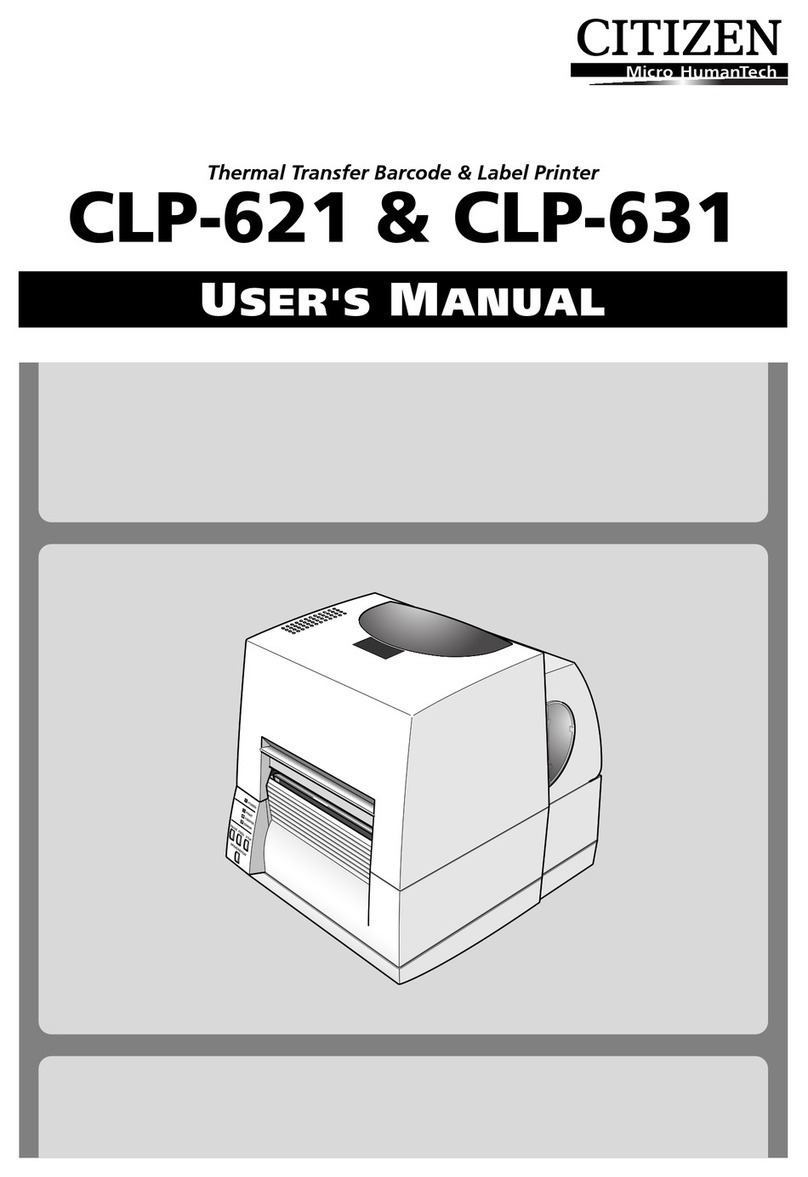
ThermalLabel&BarcodePrinter
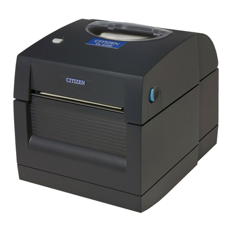
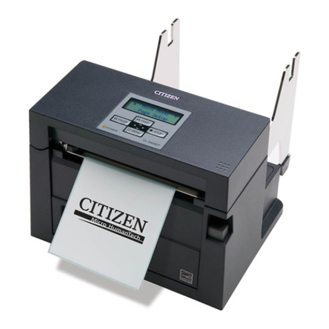
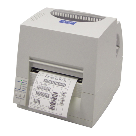
CLP-8301
For the safe operation of your printer, please read the following important operation and safety instructions
carefully. Failuretoobservetheseprecautionscanresultinpersonalinjuryor property damage or, in extreme
situation,serious injury or death.
1. Readall of these instructions and save them for later reference.
2. Follow all warnings and instructions marked on the product.
3. Unplugthis product from thewall outlet before cleaning. Donotuse liquid or aerosolcleaners, thinner,
trichloroethylene,benzine, ketone or similar chemicals. Instead use a dampclothfor cleaning, when
theprinter is disconnected from the mains supply.
4. Donot use this product near water orwhere a chemical reaction can occur suchasin a laboratory or
wherethereisalotofoil,dust,saltorironparticles.
5. Donot place this product on an unstable cart, stand or table. The product may fall, causing serious
damageto the product and people around it.
6. Slots and openings on the cabinet and the back or bottom are provided for ventilation.
7. Toensure reliable operation of the product and to protect it from overheating,donotblock or cover
theseopenings. The openings should never beblockedby placing the product onabed, sofa, rug or
othersimilar surface. This product shouldneverbe placed near or overa radiator or heat source. This
productshouldnot be placed in a built-in installation unless proper ventilation is provided.
8. Thisproduct should be operatedfrom the type of powersourceindicated on the marking label. Ifyou
are not sure of the type of power available, consult your dealer or local power company.
9. Thisproduct is equippedwitha three-pronged plug,aplug having a thirdgrounding pin. This plug will
onlyfit into agrounding-typepower outlet. This is asafetyfeature. If you are unabletoinsert the plug
into the outlet, contact your electrician to replace your obsolete outlet. Do not defeat the safety
purposeof the grounding-type plug.
10. Donotallowanythingtorestonthepower cord. Do not locate this product where the cord will be
walked on. Do not pull on the power cord or data cables or keep them under tension.
11. If an extension cord is used with this product, make sure that the total of the ampere ratings on the
productsplugged into the extensioncorddo not exceed theextension cord ampere rating. Also, make
surethat the total of all products plugged intothewall outlet does not exceed 7.5 amperes for 220/
240V outlet and 15 amperes for a 120Voutlet.
12. Neverpush objects of any kindinto this product through cabinet slotsas they may touch dangerous
voltagepoints or short out parts that could result inarisk of fire or electric shock. Never spill liquid
of any kind on the product.
13. Except as explained elsewhere in this manual, don’t attempt to service or disassemble this product
yourself. Openingand removing those covers that are marked“DoNot Remove” may expose you to
dangerousvoltage points orother risks. Refer allservicing on thosecompartmentsto service personnel.
14. The mains plug on this equipment must be used to disconnect mains power. Please ensure that the
socketoutlet is installed near the equipmentandshall be easily accessible.
15. Unplugthis product from the wall outlet and refer servicingtoqualified service personnel under the
followingconditions:
a. When the power cord or plug is damaged or frayed.
b. Ifliquid, aerosol chemicals or other chemicals have been spilled intothe product.
c. If the product has been exposed to rain or water or excessive humidity.
d. If the product does not operate normally when the operating instructions are followed. Adjust only
those controls that are covered by the operating instructions since improper adjustment of other
controlsmay result indamageand will often requireextensive work by aqualified technician to restore
the product to normal operation.
e. If the product has been dropped or knocked or the cabinet has been damaged.
f. If the product exhibits a distinct change in performance, indicating a need for service.
16. Discardor safely store theplastic packing bag. This bag shouldbe kept away fromchildren. Ifthe bag
ispulled over child’s head, it may cause suffocation.
17. Make sure if you open the top cover, it is opened all the way. If only partially open, the cover could
slamshut, possibly causinginjury.
18. When the cover is open, be careful of the corners of cover. They could cause injury.
19. Do not open the printer during printing.
20. Operate the control panel properly. A careless, rough handling may cause problems or malfunction.
Donot use such sharp-edged tool as a ballpoint for operation.
21. Ifa problem occurs during printing,stop the printer immediately andunplug the power cord fromthe
outlet.
22. Thecontentsof this manual may be changed without prior notice.
23. Reproduction,transfer, or transmission of thecontents of this manual without priorconsent is strictly
prohibited.
24. Weare not liable foranydamage resulting from theuse of the informationcontainedherein, regardless
oferrors, omissions, or misprints.
25. Weare not liableforany problems resultingfromthe use ofoptionalproducts and consumablesupplies
other than the designated products contained herein.
26. We are not liable for any damage caused by user’s erroneous use of the printer and inadequate
environment.
27. Data residing in the printer is temporary. Therefore, all data will be lost if power is lost. We are not
liablefor any damage or loss of profitscaused by data loss due to failures,repairs,inspections, etc.
28. Pleasecontact us if there are any mistakes orambiguitieswithin this manual.
29. Ifthere are missing or incorrectly collated pages in this manual, contact us to obtain a new manual.
30. Trademarks or registered trademarks of other companies and products are included in this manual.
Citizenacknowledges all trademarks.
COMPLIANCE STATEMENT
FOR EUROPEAN USERS
CE marking shows conformity to the following criteria and provisions:
LowVoltage Directive (73/23/EEC)/EN60950
EMCDirective (89/336/EEC)/EN55022, EN55024, EN61000-3-2 & EN61000-3-3
SAFETY INSTRUCTIONS
Removing Adhesive Tapes
a. The printer is shipped with adhesive tape in place to hold
the top cover closed. Simply remove the two pieces of
tape on either side of the top cover. Then open the top
cover by lifting up and tipping it backwards.
b. Thereare twopieces oftape onthe rightside ofthe printer
preventing the head release levers from being pressed.
Carefully remove these pieces of tape.
c. Lastly, there is another strip of adhesive tape holding the
mechanism closed for shipping. Remove the tape and
attached paper by carefully peeling from the case. A piece
of paper is also inside the mechanism to protect the
printhead.
Connection to Power
a. Ensure the power switch is turned OFF.
b. Connect the power cord supplied to the printer’s power cord inlet.
c. Insert the plug of the power cord in the AC outlet.
d. Turn the power switch on and the LCD panel on the front of the
printer will display “Power On” and, after a few seconds of testing,
it will display “Ready”.
Connection to a Computer
This product has two interfaces as standard that can be used to receive printing data: a serial
port(RS232C) and a parallelport. Anoptional internal Ethernet (LAN)port,an internal Wireless
LANport or enhanced “1284” parallel port can be added by yourdealer. Withthe exception of
awireless LAN connection, an interface cable is necessary to connect the printertoa computer.
a. With the power turned off, connect one end of the interface cable
to the interface connector on the back of the printer and secure it
with locks or locking screws, where available.
b. Connect the other end of the interface cable to the interface
connector on the computer and secure it with locks or locking
screws, where available.
Caution Usean AC outlet thatacceptsa three-pronged plug.
Otherwise, static electricity may be generated and
there will be danger of electric shock.
3Connection
2Remove Packing
Power Switch
Power Cord Inlet
PC card socket
(notusually
installed)
Mediaviewing
window
Embossedpattern
to make opening
easier
Front of printer
SerialPort
Parallel port (or
network card
option)
Blankingplate
Congratulations....
On your choice of a Citizen CLP 8301 label printer.
Pleasetake a moment to read this Quick Start Guidewhichwill familiarise yourself with the
printerand its operation. Theprinter is a sophisticatedbut easy-to-use label printerfeaturing
simplemedia loading, quick connection anda powerful LCD configuration system.
We will guide you through unpacking of the printer from its carton, connection to your
computer system and installation of the media including a quick self-test of the printer to
ensure it is working.
Safety
Butfirst, please carefully readthe safety instructions includedinthis Quick Start Guideand in
moredetail in the user manual. Failureto observe the safety precautionscouldcause serious
injury or damage to both you and your property.
Unpacking Your Printer
Carefully openthe carton and lift out the upper foam damper containing the accessories.
Withtwo hands and, ifnecessary with someone else’sassistance, lift the printeroutof the box
holdingthe bottom of theprinterfirmly. Ensure there is spacetoset the printer down before
you lift it from the packing. Keep the carton, packing materials and printer mechanism
travellingtape for future shipment.
Insome cases, yoursupplier or Citizenmayhave added extraitems required for yourparticular
installation such as additional CD-ROM, cable or manuals. Instructions for each of these
itemswill be included within theindividualpackages.
Ifyou have any questions,orif you find anyof the items are missing,please initially refer back
toyour supplier. Otherwise, contact detailsfor our offices areshown on the backpage of this
QuickStart Guide.
1Read This First!
Carton Contents - Accessories
Windows®Driver Installation
Ifyou are using Windows®98, NT4, 2000,XPor 2003 or any newerversionsof Windows®, the
latestprinter drivers will usually besuppliedon CD in the boxby your dealer. If the drivers are
notincluded with the printer, youcandownload the latest version free-of-chargefrom our web
site,details of which are on the back of this Quick Start Guide.
Under the latest versions of Windows®, the computer will often automatically detect the
presence of the printer. Therefore it is advisable to download the drivers from our web site
beforeinstalling theprinterso the filesare ready forinstallation. Follow any on-screeninstruction
andalsoinstructionssuppliedwithanyadditionalCD-ROMorfloppydisk included with your
printer.
Your supplier will assist you with the correct drivers and software which are compatible with
your particular computer system if you are not using Windows®. Windows®is a trademark of
Microsoft®Corporation.
ForFurther Information ...
For further information and more detailed instructions on the use of
your new printer, please refer to the complete user manual accompanying
your printer.
Alternatively, please contact one of our local sales offices:
Citizen Systems Europe GmbH
Mettinger Strasse 11
D-73728 Esslingen
Germany
Tel: +49 (0) 711 3906 400
http://www.citizen-europe.com
Citizen Systems Europe UK
Park House, 643-651 Staines Road
Feltham, Middlesex, TW14 8PA
United Kingdom
Tel: +44 (0) 20 8893 1900
http://www.citizen-europe.com
Citizen America Corporation
2102 Alton Parkway, Unit A
Irvine, CA 92606. U.S.A.
Tel: (949) 428-3700
http://www.citizen-america.com
Ribbonbobbins
(2pieces)
Sampleribbon
Cardboardcore
Power cord
UserManual
Samplemedia
Head
cleaningpen
Mediaholder disks
(2pieces)
Mediaholder shaft
Upperfoam damper including
accessories,detailed above
Printer
Lower foam damper
(Thisdoes not need to be
removed from the carton)
Carton
