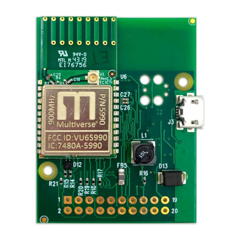
City Theatrical 5792 SHoW DMX Neo User manual

SHoW DMX Neo® OEM Guide
Rev 2.2
©2014 City Theatrical Inc.
SHoW DMX Neo device are covered by U.S. Patent #7,432,803.

Table of Contents
1 Revision History .............................................................................................................. 5
2 Product Overview ........................................................................................................... 6
2.1 Part Number ................................................................................................................... 6
2.1.1 5792 SHoW DMX Neo Radio Module for OEM ......................................................... 6
2.1.2 5794 SHoW DMX Neo Radio Module for W-DMX .................................................... 6
3 About this Manual .......................................................................................................... 7
Specifications ................................................................................................................. 8
4.1 Regulatory Specification ................................................................................................. 8
4.1.1 FCC Part 15 ................................................................................................................ 8
4.1.2 Radio Frequency Notification .................................................................................. 9
5 Neo Operation Mode Implementation .......................................................................... 13
5.1 SHoW DMX Neo Radio for OEM (P/N 5792) .................................................................. 13
Table : SHoW DMX Neo Radio for OEM Signal Descriptions ................................................ 1
5.1.1 De cription of Signal Pin ........................................................................................ 14
5.1.2 Recommended Interface Connection Example ..................................................... 20
5.2 SHoW DMX Neo Radio for W-DMX (P/N 5794) ............................................................. 22
5.2.1 De cription of Signal Pin ........................................................................................ 24
6 Classic Operation Mode Implementation ...................................................................... 26
7 Serial Configuration Protocol ........................................................................................ 27
7.1 SHoW ID to Regi ter Table ............................................................................................ 37

List of Figures
Figure 1: SHoW DMX Neo Radio for OEM to Ho t Interface ........................................................ 13
Figure 2: SHoW Baby 5 Signal Implementation ............................................................................ 21
Figure 3: Minimum Signal Implementation .................................................................................. 22
Figure 4: Config Regi ter Read & Write Protocol ......................................................................... 28

List of Tables
Table 1: Revi ion Hi tory ................................................................................................................. 5
Table 2: Radio Module Specification ............................................................................................. 8
Table 3: Li t of Approved Antenna .............................................................................................. 10
Table 4: SHoW DMX Neo Radio for OEM Signal De cription ...................................................... 14
Table 5: Signal Strength Truth Table ............................................................................................. 15
Table 6: GPI RDM Per onality Selection ....................................................................................... 17
Table 7: GPI Function after Power-Up .......................................................................................... 18
Table 8: SHoW DMX Neo Mode Selection Table .......................................................................... 20
Table 9: SHoW DMX Radio for W-DMX Signal De cription ......................................................... 24
Table 10: Statu LED function ....................................................................................................... 24
Table 11: Config Error Code ........................................................................................................ 27
Table 12: Overview of Configuration Regi ter ............................................................................ 28
Table 13: Detailed De cription of Configuration Regi ter .......................................................... 29
Table 14: SHoW DMX Neo ID to Radio Regi ter .......................................................................... 37
Table 15: SHoW DMX Cla ic ID to Radio Regi ter ...................................................................... 38

1Revision History
Table 1: Revision History
Revision
Date
Description
Author/Changed
1.0
Oct. 12, 2011
Initial Relea e
P. Klei ler
1.1
Oct. 24, 2011
Moved Logic Level Specification in
Table
2
to DC
Characteri tic ection. Updated Table 4 for internal
pull-up and removed 3.3v reference
P. Klei ler
2.0
May 12, 2014
Split Cla ic from Neo. Added Neo example
P. Klei ler
2.1
June 30, 2014
Minor edit and revi ion
V. Ti dale
2.2
Dec 08, 2014
Added extended
frequency range and 5
-
channel ub
-
band
Updated approved antenna li t
Removed “and other patent pending” from cover
page
B. Au

2Product Overview
The SHoW DMX Neo (Neo) radio module wa de igned by City Theatrical, Inc. (CTI) to u e in the
SHoW DMX line of wirele theatre lighting control equipment. Thi equipment i u ed for
wirele tran mi ion and reception of DMX512-A and RDM protocol data.
The Neo radio module wa de igned to provide enhanced interference rejection, to reduce
latency of both DMX and RDM packet delivery and provide an ea ier interface to implement.
The Neo radio module can operate in two different mode : Neo and Cla ic. It i recommended,
however, to implement only Neo mode. Cla ic mode i backward compatible with the
previou generation technology, formally known a SHoW DMX. .
The SHoW DMX product line u e SHoW ID to allow device to communicate with each other.
A long a two (or more) device are programmed to hare a SHoW ID, they will be able to
communicate. The SHoW ID i programmed into the module via the “config” protocol, RDM or
an external button.
2.1 Part Nu bers
The Neo radio module come in two different ver ion . The part number and difference are
found below.
2.1.1 5792 SHoW DMX Neo Radio Module for OEM
The 5729 u e a 40-pin low profile header. The header contain all ignal allowing the unit to
be integrated in the mo t flexible way. The ignal are all TTL (tran i tor –tran itor logic) and
the voltage ource i fixed at 5Vdc.
2.1.2 5794 SHoW DMX Neo Radio Module for W-DMX
The 5794 u e a 10-pin header. The header contain ignal that directly map to the W-DMX
module. Thi ver ion ha an on board RS-485 driver and can accept voltage of 5Vdc fixed or 7-
30Vdc u ing the onboard witching regulator.

3About this Manual
Section 4 provide the pecification , notification and regulation nece ary for afe and
effective operation of the SHoW DMX Neo Radio.
Thi manual divide the two operating mode into eparate ection : Neo operation mode
implementation and Cla ic operation mode implementation. It i not recommended to
implement the latter.
Section 5 de cribe implementing Neo mode. The ection i broken into two ub ection , one
for the 5792 (SHoW DMX Neo Radio for OEM) and one for 5794 (SHoW DMX Neo Radio for W-
DMX). Neo mode implementation are the preferred method of integration.
Section 5.1.2 give example of common implementation . It i ugge ted to follow one of
the e example .
Section 6 wa intended to de cribe the implementation of Cla ic mode. However, CTI trongly
recommend it cu tomer avoid implementing Cla ic mode and thu ha excluded ection 6
from thi manual. If compatibility to older SHoW DMX product i required, Cla ic mode mu t
be implemented a an addition to Neo mode. If you are intere ted in pur uing uch
functionality, plea e contact City Theatrical at (201)-549-1160.
Section 7 de cribe the protocol and command et for the configuration mode.

4Specifications
Table 2: Radio Module Specifications
Physical Characteristics
Size 1.90 x 2.65 x 0.20 inches
Connector 40 pin header – Amp P/N 177986-1
Antenna connector Horizontal MMCX coaxial receptacle
Operating Temperature -20 to +70 deg C
Storage Temperature -40 to +85 deg C
DC Characteristics
Input Voltage 5 Volts DC ±2%, ±5mV ripple
Current draw 0.18 Amps maximum
Sleep mode current 20mA maximum
Logic levels 3.3 Volt / 5V Tolerant
Transmitter Characteristics
TX power Selectable 1mW to 72mW in four
steps
Frequency range 2406 to 2480 MHz
Modulation FSK frequency hopping
Over-the-air data rate 1 Mbps
Channel coding 8B/10B line coding See note 1
Hopping patterns 2 sets of 36 full band, 2 sets of 16 low,
mid, & high partial band selectable
patterns with low cross-correlation
and selectable adaptive hopping
algorithms; 2 sets of partial band fixed
patterns
Receiver Characteristics
RX sensitivity -95 dBm @ 1% PER
Error checking CRC32
Serial Interface
Bit rate Classic: 1.25 Mbps
Neo: 250Kbps
Data Format Classic: 8 N 1; Neo: 8 N 2
Flow Control None
Note 1: The effective bit rate will be 800Kbp rather than 1Mbp u ing 8B/10B coding.
4.1 Regulatory Specifications
4.1.1 FCC Part 15
Thi equipment ha been te ted and found to comply with the limit for a Cla B digital device,
pur uant to part 15 of the FCC Rule . The e limit are de igned to provide rea onable
protection again t harmful interference in a re idential in tallation. Thi equipment generate

u e and can radiate radio frequency energy and, if not in talled and u ed in accordance with
the in truction , may cau e harmful interference to radio communication . However, there i
no guarantee that interference will not occur in a particular in tallation. If thi equipment doe
cau e harmful interference to radio or televi ion reception, which can be determined by
turning the equipment off and on, the u er i encouraged to try to correct the interference by
one or more of the following mea ure :
•Re-orient or re-locate the receiving antenna.
•Increa e the eparation between the equipment and receiver.
•Connect the equipment into an outlet on a circuit different from that to which the
receiver i connected.
•Con ult the dealer or an experienced radio/TV technician for help.
4.1.2 Radio Frequency Notifications
4.1.2.1 FCC Notifications
RF Radiation: The Product i an intentional radiator of Radio Frequency (RF) energy. In order to
limit RF expo ure to per onnel in the immediate area, the Product hould be located and
in talled uch that a eparation of at lea t 20 centimeter i maintained between the Product’
antenna and per onnel in the vicinity of the device. The antenna u ed for thi tran mitter mu t
not be co-located or operated in conjunction with any other antenna or tran mitter.
Modification warning: Caution - change or modification to thi equipment, not expre ly
approved by City Theatrical, Inc. could void the u er’ authority to operate the equipment.
4.1.2.2 Industry Canada Notifications
Thi Cla B digital apparatu complie with Canadian ICES-003. Operation i ubject to the
following two condition : (1) thi device may not cau e interference, and (2) thi device mu t
accept any interference, including interference that may cau e unde ired operation of the
device.
Cet appareil numérique de la cla e B e t conforme à la norme NMB-003 du Canada.
4.1.2.3 Approved Antennas
To reduce potential radio interference to other u er , the antenna type and it gain hould be
o cho en that the equivalent i otropically radiated power (e.i.r.p.) i not more than that
required for ucce ful communication. Thi device ha been de igned to operate with the
antenna li ted in
Table 3 below. Antenna not included in thi li t are trictly prohibited for u e with thi device.
The required antenna impedance i 50 ohm .

The device can be configured with any one of the approved antenna li ted in Table 3 for fixed,
point-to-point (one erver and one client) configuration. When the device i configured for
point-to-multipoint (one erver and multiple client , client talk to erver only one at a time)
configuration, the client can u e any of the approved antenna erver can u e any approved
antenna li ted in Table 3 except the 14dBi Yagi directional antenna.
Table 3: List of Approved Antennas
Manufacturer Model Type Connector Gain
(dBi)
1 Near on S151AH-2450S Omni whip SMA plug rever e polarity 5
2 Near on DG102N-2.4/5.25 Omni whip SMA plug rever e polarity via
provided antenna cable
5
3 Tekfun F40-N Omni whip SMA plug rever e polarity via
provided antenna cable
4.5
4 Near on S152AH-2450S Omni whip SMA plug rever e polarity 4
5 Near on S141AH-2450 Omni whip SMA plug rever e polarity 2
6 Near on S131AH-2450S Omni whip SMA plug rever e polarity 2
7 Centurion WCP2400-MMCX4 Omni whip MMCX jack on 4” coax pigtail
2.5
8 Near on SPCB07257 Omni
Printed
Trace
MMCX jack on 4” coax pigtail 2
9 PCTEL Maxrad MP24008XFPT Panel SMA plug rever e polarity via
provided antenna cable
8
10 PCTEL Maxrad MYP24010PT Yagi SMA plug rever e polarity via
provided antenna cable
10
11 PCTEL Maxrad MYP24014PT Yagi SMA plug rever e polarity via
provided antenna cable
14

4.1.2.4 FCC & IC ID Label
The FCC & Indu try Canada (IC) ID label on the CTI # 5792/5794 module mu t be vi ible through
a window on the final product or it mu t be vi ible when an acce panel, door or cover i ea ily
removed. If not, a econd label mu t be placed on the out ide of the final product that contain
the following text : “Contain FCC ID: VU65792M” and “Contain IC ID: 7480A-5792M”.
4.1.2.5 CE Mark Confor ity
City Theatrical Inc. declare that thi product conform to the pecification li ted in the
manual, following the provi ion of the European R&TTE directive 1999/5/EC.
City Theatrical Inc. vakuuttaa täten että die e produkt tyyppinen laite on direktiivin 1999/5/EY
oleelli ten vaatimu ten ja itä ko kevien näiden direktiivien muiden ehtojen mukainen.
City Theatrical Inc. déclare que le produit e t conforme aux condition e entielle et aux
di po ition relative à la directive 1999/5/EC.
•EN 301 489-1, 301-489-17 General EMC requirement for radio equipment.
•EN 60950 Safety.
•EN 300 328 Technical requirement for radio equipment.
CAUTION – This equipment is intended to be used in all EU and EFTA countries. Outdoor use may
be restricted to certain frequencies and or may require a license for operation. Contact local
authority for procedure to follow.
Note: ESD precaution hould be u ed when attaching or removing the antenna.
Note: Combination of power level and antenna re ulting in a radiated power level of above
100mW equivalent i otropic radiated power (EIRP) are con idered a not compliant with the
above mentioned directive and are not allowed for u e within the European community and
countrie that have adopted the European R&TTE directive 1999/5/EC. For more detail on
legal combination of power level and antenna , contact City Theatrical Inc.
Do not u e thi product near water, for example, in a wet ba ement or near a wimming pool.
Avoid u ing thi product during an electrical torm. There may be a remote ri k of electric hock
from lightning.

4.1.2.6 Regulatory Infor ation
Radio Frequency Notification
Belgique Dan le ca d'une utili ation privée, à l'extérieur d'un bâtiment, au-de u d'un e pace
public, aucun enregi trement n'e t néce aire pour une di tance de moin de 300m. Pour une
di tance upérieure à 300m un enregi trement auprè de l'IBPT e t requi e. Pour une utili ation
publique à l'extérieur de bâtiment , une licence de l'IBPT e t requi e. Pour le enregi trement
et licence , veuillez contacter l'IBPT.
France 2.4 GHz Bande : le canaux 10, 11, 12, 13 (2457, 2462, 2467, et 2472 MHz
re pectivement) ont complètement libre d'utili ation en France (en utili ation intérieur). Pour
ce qui e t de autre canaux, il peuvent être oumi à autori ation elon le département.
L'utili ation en extérieur e t oumi e à autori ation préalable et trè re treint. Vou pouvez
contacter l'Autorité de Régulation de Télécommunication (http://www.art-telecom.fr) pour
de plu ample ren eignement .
5Neo Operation Mode I ple entation
Thi ection will cover the 5792 and 5794 module eparately.
When operating in Neo mode, the radio module output TTL DMX/RDM protocol on it
TxD/RxD erial line . An RS-485 direction control line i available for connection to a driver IC if
nece ary. If RDM i enabled in the module, it will al o perform RDM di covery of any RDM
enabled wired device connected to it erial port. Configuration i performed by witching the
module to "config" mode u ing the MODE0/MODE1 ignal line bit .
5.1 SHoW DMX Neo Radio for OEM (P/N 5792)
Below i a block diagram of the complete ignal connection that make up the interface. See
5.1.1 for de cription of ignal pin . It i not nece ary to u e all pin . See ection 5.1.2 for other
option .
Figure 1: SHo DMX Neo Radio for OEM to Host Interface
Ho t Radio Module
LN Mode
Tx/Rx mode
In Range
Signal Low
Signal Med.
Signal High
485 Direction
Tx Data
Rx Data
29
15
28
9
11
13
31
14
16
UART Rx; Driver
UART Tx;
Driver
17
19
DMX Valid
7
GPI1
GPI0
Mode 0
Mode 1
32
34
GND
GND; I/O
GND; I/O
NC; I/O
NC; LED; I/O
NC; LED; I/O
NC; LED; I/O
NC; LED; I/O
NC; LED; I/O
NC; Driver
NC; GND; I/O
NC; GND;
I/O

Table 4: SHo DMX Neo Radio for OEM Signal Descriptions
Pin
Type Signal Name Function Notes
1 GND GND Signal Ground
3 VCC VCC 5VDC
5 VCC VCC 5VDC
7 O DMX_VALID DMX Valid 1/2sec toggle rate when not present
9 O SIG_LOW Signal Strength Low Active high
11 O SIG_MED Signal Strength Medium Active high
13 O SIG_HI Signal Strength High Active high
14 O TxD Transmit data from radio
15 I Tx/Rx Selects Tx/Rx mode low = Tx, high = Rx, Internal Pull-up
16 I RxD Received data from host
17 I GPI1 General input Bit 1 Controls RDM personality, see docs
19 I GPI0 General input Bit 0 Controls RDM personality, see docs
20 GND GND Ground
21 GND GND Ground
23 O RED RGB LED Red SHoW Baby 5 SHoW ID Indication
26 O BLUE RGB LED Blue SHoW Baby 5 SHoW ID Indication
27 O GREEN RGB LED Green SHoW Baby 5 SHoW ID Indication
28 O IN_RANGE Rx in range of Tx Active High
29 I LN Mode Classic/Neo mode low = Neo, Internal Pull-Up
30 I 485 Rx Only Wired RDM Responder
mode Active Low, Internal Pull-Up
31 O 485 Dir RS485 Direction Control RX = Low, TX = High
32 I Mode Bit 0 Mode Bit 0 Internal Pull-Up
34 I Mode Bit 1 Mode Bit 1 Internal Pull-Up
36 I WakeUp Take radio out of sleep Active Low, Internal Pull-Up
37 I Bootload Enter Boot Loader mode Active low, Internal Pull-Up
38 I µP_RESET Radio Reset Active Low
39 VCC VCC 5VDC
40 GND GND Signal Ground
5.1.1 Description of Signal Pins
Pin 7 – DMX_VALID: Thi pin indicate the pre ence of valid DMX frame at the input when
operating in erver mode or valid DMX frame at the output when operating in client mode.
When no valid frame are pre ent, the pin toggle at a ½ econd rate.
Pin 9, 11 & 13 – SIG_LOW, MED, HI: The e pin provide an indication of ignal trength. The
flowing chart define the tate of the output .

Table 5: Signal Strength Truth Table
Signal Range
State
Pin 9
Pin 11
Pin 13
-
30dbm
–
-
60dbm
HI
High
High
High
-
61dbm
–
-
75dbm
MED
High
High
Low
-
76dbm
–
-
90dbm
LOW
High
Low
Low
-
91dbm
–
-
120dbm
No
Signal
Low
Low
Low
Pin 1 – TxD: Thi pin i the TTL erial data output from the radio module. The data conform to
DMX/RDM when in “Neo” mode or configuration protocol when in “config” mode. Mode are
elected via the MODE0/MODE1 pin de cribed in

Table 8.
Pin 15 – Tx/Rx: Thi pin i an input to et the radio to either tran mitter mode or receiver
mode. In tran mitter mode the radio tran mit data wirele and receive DMX data wired. In
receiver mode the radio earche for a tran mitter from which to receive wirele data and
generate wired DMX/RDM data ba ed on the SHoW ID etting. See Table 4 for more detail .
Pin 16 – RxD: Thi pin i the TTL erial data input to the radio module. The data conform to
DMX/RDM when in “Neo” mode or configuration protocol when in “config” mode. Mode are
elected via the MODE0/MODE1 pin de cribed in

Table 8.
Pins 17 & 19 – General Input Bits: The e two pin control the per onality of the internal RDM
re ponder. The e input are only read at power up, and then depending on mode are u ed for
other purpo e . The e input have internal pull-up and can be left unconnected for per onality
SHoW Neo. See Table 6 for de cription of the different per onalitie . Table 7 de cribe the
function the pin take on after power up ha completed.
Table 6: GPI RDM Personality Selection
GPI1, GPI0 Personality Description
0, 0 Ho t Ho t mu t a ume radio’ UID and an wer all me age .
0, 1 SHoW Baby Radio Module an wer all RDM me age a defined for a SHoW
DMX SHoW Baby product. Ho t i treated a a di covered device.
1, 0 Vero Radio Module an wer all RDM me age a defined for a SHoW
DMX Vero product. Ho t i treated a a di covered device.
1, 1 SHoW Neo Full RDM Mode. Full et of upported PID re ponded to by radio.

Table 7: GPI Function after Power-Up
RDM Personality
GPI1 Function
GPI0 Function
Ho t
None
None
SHoW Baby
None
Toggle SHoW ID
Vero
Re et ID to 201
if held low for .5
None
SHoW Neo
None
Re et ID to 201 if held low for .5
Pin 23 & 26 & 27 – Red/Blue/Green: The e pin are only u ed when the RDM per onality i
SHoW Baby. SHoW Baby indicate it current SHoW ID by di playing a color on an RGB LED. Pin
23 control the Red element, 26 control the Blue and 27 control the Green.
Pin 28 – IN_RANGE: Thi pin i an output that i only active when the radio i in receiver mode.
It indicate whether the radio module i receiving and i ynchronized to a tran mitter or not by
going high when it i ynched.
Pin 29 – LN_MODE: Thi pin elect the operational mode , active low for SHoW DMX Neo. Thi
pin i internally pulled high. Thi pin mu t be pulled low to enable “Neo” operation. Thi pin i
latched at re et in regi ter 0x15, after re et, the mode can be changed by writing to regi ter
0x15.
Pin 30 – 85RX_ONLY: Thi pin put the SHoW DMX Neo into RDM wired re ponder mode. Thi
pin i internally pulled high. When pulled low, the SHoW DMX Neo will drive the “485 Dir”
ignal low. Thi can be connected to a witch to effectively deactivate the SHoW DMX Neo from
the 485 bu and allow the SHoW DMX Neo to act like a RDM re ponder on the 485 bu .
Note: Thi pin can only be driven active during a DMX/RDM break through byte 23 of
current the DMX/RDM frame. Driving thi pin active at other time can cau e
undefined re ult .
Pin 31 – 85DIR: Thi pin allow an off board RS485 driver to be connected directly to the TTL
erial ignal and allow the SHoW DMX Neo to communicate on the DMX/RDM bu without the
need of a ho t proce or.
Pin 32 & 3 – Mode Selection: The e two pin are input that control whether the radio i in
“Neo” mode or “config” mode. Neo mode i for normal DMX/RDM operation. Config mode i
u ed to configure the internal radio regi ter via the erial configuration protocol found in
ection 7. The e pin have weak pull-up . See

Table 8 below for the mode election truth table.

Table 8: SHo DMX Neo Mode Selection Table
Bit 1
Bit 0
Mode
De cription
0
0
Neo Mode
Normal operation DMX/RDM
0
1
N/A
Invalid
1
0
Config Mode
Read/Write internal configuration regi ter
1
1
N/A
Invalid
Notes:
•When the mode bit change, the radio abort it current operation and enter the newly
elected mode.
•You can only change to “config” mode during a DMX/RDM break through byte 23 of the
current DMX/RDM frame. Selecting “config” mode active at other time can cau e
undefined re ult .
Pin 36 – Wakeup: After the radio ha been put into leep mode by writing to the leep regi ter,
thi pin i u ed to wake the radio back up. The pin i held high with an internal pull-up re i tor
and the ho t mu t pull it low to wake up the radio.
Pin 37 – Bootload: Thi pin tell the radio to enter bootloader mode. It i read on power up /
re et. If logic 0, radio enter bootloader mode. Contact CTI if you need information on how to
load new code into the radio module.
Pin 38 – Reset: Thi pin i connected directly to the re et pin of the microcontroller in the radio
and i u ed by the ho t CPU to force the radio to perform a re et. After pulling thi pin low and
then relea ing it the radio’ firmware will tart running from the beginning and will load all the
configuration regi ter with the default value . After relea ing the re et pin the radio take
approximately 60mS before it i ready to communicate with the ho t proce or.
5.1.2 Reco ended Interface Connection Exa ples
5.1.2.1 Exa ple: SHoW Baby 5 Receiver
Thi example how how to integrate the functionality of a SHoW DMX SHoW Baby 5 receiver
into your application. Figure 2 below how the connection required to imulate the feature
et of the SHoW DMX SHoW Baby 5 product operating a a SHoW DMX receiver.
In thi mode the LN_MODE ignal i tied low to put the radio module into “Neo” operation
mode. Leaving the Tx/Rx ignal input unconnected cau e the module to operate a a receiver.
Both mode bit are tied to common to permanently leave the module in the “Neo” operation,
a we will not be u ing the configuration protocol in thi example. GPI0 i connected to a
normally open witch o that we can toggle thru the 5 SHoW Baby ID that are available in thi
configuration. An RS-485 half duplex driver i connected to the TxD/RxD and 485 direction line .
The remaining ignal left all connect to LED indicator .
This manual suits for next models
1
Table of contents
Other City Theatrical Control Unit manuals
Popular Control Unit manuals by other brands

IFM Electronic
IFM Electronic Ecomot300 AC2630 operating instructions

Waters
Waters 2545 Binary Gradient Module Operator's guide

BERMAD
BERMAD 720 manual

Cooper Notification
Cooper Notification SP4-RMX installation instructions

Bennett
Bennett PULSER manual

Moog
Moog D765 series Mounting and Installation Notes

Lindab
Lindab Airy Assembly instructions

Icop
Icop VSX-6127-V2 user manual

IME
IME Nemo SX manual

National Instruments
National Instruments 2591 installation guide

GEM
GEM iComLine CleanStar C57 HPW Installation, Operating and Maintenance Instruction

Datakom
Datakom DKG-153 Installation and operating instructions