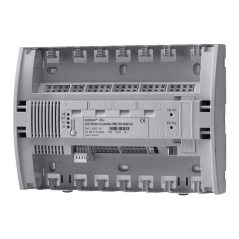
Clauss CIRCON 4260007480120 User manual

Der elektronische Zirkulationscontroller
The electronic circulation controller
Le dispositif de contrôle électronique de circulation
De elektronische circulatiecontroller

1
Sparprogramm/Economy program/Programme économique/Energiebesparend programma:
Position / Positie 0 1 2 3 4
max. Laufzeit / max. running time /
Temps de fonctionnement maximal /
Maximale inschakelduur
5 min 10 min 15 min 20 min 30 min
Automatikprogramm/Automatic program/Programme automatique/Automatisch programma:
Position / Positie 5 6 7 8 9
max. Laufzeit / max. running time /
Temps de fonctionnement maximal /
Maximale inschakelduur
5 min 10 min 15 min 20 min 30 min
Komfortprogramm/Comfort program/Programme de confort/Comfortabel programma:
Position / Positie ABC D EF
Intervall / Interval /
Intervalle / Tussentijd 5 min 10 min 15 min 20 min 30 min 40 min
max. Laufzeit / max. running
time / Temps de
fonctionnement maximal /
Maximale inschakelduur
2 min 5 min 8 min 10 min 15 min 20 min

2
Scope of supply
Basic device with 2 temperature sensors,
Cable fastener, adhesive fabric tape,
Operating Manual
Functional description
The circulation controller CIRCON is a modern, microcontroller-controlled device for activating the
circulation of hot water in a heating system depending on consumption.
Two temperature sensors monitor the changes in the flow and return temperatures in the circulation circuit.
When water is withdrawn from the cooled down circuit, hot water rises from the heat storage tank into the
flow pipe so that the pipe heats up rapidly. The temperature rise signals to CIRCON that water has been
withdrawn, causing it to start the circulation pump. Thus, just briefly opening a hot-water tap at any point
in the circuit will suffice for initiating circulation. Circulation stops automatically after a predetermined
operating time is reached or after the water in the return pipe has also become sufficiently heated,
whatever occurs earlier. If no return-line sensor has been connected, circulation always is switched off
after the predetermined operating time.
In case of excess temperature of the water in the flow pipe, starting of the circulation pump is prevented.
To avoid the multiplication of Legionella and putrefaction, the circulation pump is automatically activated
once after every 48 hours during periods in which no water has been withdrawn.
Controls and indicators
All operating states are signalled via three coloured LEDs:
Flashing light green: Basic device ready for operation, flow and return temperatures are monitored.
Steady light yellow: Circulation pump is on.
Steady light red: Excess temperature in flow pipe.
Flashing light red: Flow-pipe sensor fault (not connected, line interruption or short-circuit)

3
Operating mode selector switch (works setting = 7, operation with screwdriver) (_ page 2):
Economy program:
Function: Circulation starts after water has been withdrawn for a short time.
Advantage: Maximum energy saving effect.
Disadvantage: Hot water not immediately available at any time.
Important: Never let the water run until hot water comes out of the tap. Briefly turning on the
hot-water tap for one or a few seconds suffices for activating circulation. After a
certain time, which depends on the flow rate of the water (volumetric delivery of pump),
hot water can be withdrawn immediately after the tap is turned on.
Automatic program:
Function: As economy program. In addition, recurrent consumption times are learned and
continually updated.
Advantage: No waiting time required for periodically recurring water consumption patterns. Energy
saving effect is nevertheless high.
Disadvantage: If hot water is needed outside the regular pattern, hot water is not available immediately at
any time.
Comfort program:
Function: As automatic program. Additionally, a cyclic activation function which activates the pump
in certain intervals irrespective of consumption .
Advantage: Depending on the length of the interval, hot water is immediately available at any time.
Disadvantage: Only moderate energy saving effect (will be the higher the longer the intervals are)

4
For an optimum utilisation of the advantage offered by the circulation controller, do not turn on any hot-
water tap unless you do not want to wait for the hot water to come (e.g. if you just wish to briefly wash
your hands). To remind the users of this, the scope of supply also includes stickers.
Installation
Important ! Read and observe safety hints before starting the installation !
Selecting the temperature measuring positions
The appropriate selection of the installation position and correct attachment of the temperature
sensors is of decisive importance for the proper functioning of the device.
Identifying the appropriate pipes on the hot-water storage tank:
1) All pipes directly connecting the hot-water storage tank to the heating and hot-water boiler or heating
circuit should not come up for closer consideration.
2) Characteristic features of the flow pipe (riser):
- is usually not connected to the top side of the hot-water storage tank
- is not directly connected to the cold-water pipe
- is not fitted with a pump
- in most cases, a three-way mixer valve (thickened T-piece) is installed
3) Characteristic features of the return pipe (circulation line):
- may be connected to the hot-water storage tank from the side or from the top
- has often a smaller cross-section than the flow pipe
- is fitted with the circulation pump
4) To be on the safe side:
- feel the temperature on the pipes coming into question with the circulation pump running
- switch off circulation pump for about 30 min; do not withdraw hot water during this time (the two
pipes of the hot-water circuit will now slowly cool down).

5
Adhesive fabric tape
Sensor
Pipe
- switch on circulation pump again; now, first the flow pipe and then the return pipe will heat up.
Selecting the measuring position in the flow pipe:
If the sensor is fitted closer to the hot-water storage tank, the water quantity required for activating the
circulation pump will be smaller. However, the temperature changes in the storage tank itself will also
have a greater impact. In particular with continuous copper pipes, it is advisable to position the sensor at a
sufficiently large distance from the tank. If there is a mixer valve in the circuit, install the flow sensor
between the valve and the storage tank. Practical experience has shown that distances to the storage tank
of about 20 to 40 cm are appropriate. With copper pipes, a somewhat greater distance, and with plastic
pipes, a somewhat smaller distance should be chosen.
For systems including different materials, the following applies: Prefer metal to plastics and thin-walled to
thick-walled parts for fitting the sensors.(Further useful hints can be found at www.dr-clauss.de/circon).
The measuring point in the return pipe is not critical, but it should be located as far away as possible from
the hot-water storage tank.
Important: If you have changed the locations at which the sensors have been mounted, you have to
newly start CIRCON. (Pull device out of socket outlet for a few seconds.)
Attaching and connecting the temperature sensors
Fasten sensors by means of adhesive fabric tape (included in scope of supply) longitudinally relative to the
pipe so that the silicone sheath is uniformly pressed over its entire length with its concave contact surface
onto the surface of the pipe. Make sure that no adhesive tape or other foreign matter comes to be placed
between the sheath and the pipe and that the ends of the sensors are not bent.

6
Please mind the following:
♦Use only the adhesive tape supplied for this purpose for fastening the sensors! Do not use
cable fasteners or any other adhesive tapes!
♦Do not tear the silicone sheath. Do not expose to tensile forces!
♦Exercise greatest care when fastening the sensors. Insufficient heat contact with the pipe
may severely affect the proper functioning of the device.
Lay the connecting leads in the direction of the basic device along the pipes or pump connection line so
that persons cannot become caught or trip. Tighten the supplied cable fasteners only slightly so as not to
constrict the cables.
Plug in the two sensor connectors on the side of the circulation controller in accordance with the colour
marking.
red = temperature sensor on flow pipe
blue = temperature sensor on return pipe
Putting into operation
-Set desired operating mode on selector switch.
-Connect sensors.
-Plug mains plug of circulation pump into socket outlet of basic device.
-Plug basic device into 230V/50Hz wall-mounted socket outlet.
Functional test
-Green LED flashes and signals readiness for operation.
-If the hot-water line has already sufficiently cooled down, the pump must be activated when hot
water is withdrawn from the circuit at any point in the house (activation is signalled by the lighting up
of the yellow LED). The pump must be deactivated on expiry of the selected running period or prior
to this when the temperature of the water in the return pipe has become sufficiently high.

7
Maintenance
The device is completely maintenance-free. Use exclusively a dry cleaning cloth for cleaning. Solvents or
sharp-edged tools must not be used.
Troubleshooting
Fault Possible cause Remedy
•After the pump switches on,
the time it takes till hot water
is available at the various taps
differs, sometimes by many
minutes
•Controller switches off
although hot water has not
yet been supplied to all taps
•Fault in the piping system:
No optimum cross-
sections in partial circuits
or bypasses exist in the
system
•Pump capacity too low
•Let controller operate
without return sensor:
Switch off pump after a
fixedly set time
•Use pump with a greater
capacity
•Pump switches on during
heating up of the water in the
hot-water storage tank
although no tap has been
turned on
•Flow sensor arranged too
close to the hot-water
storage tank. Heat contact
to storage tank too close
•Hot-water storage tank
heats up very fast
•Install flow sensor at a
point located farther away
from storage tank
•Do not make any changes
(if no water is withdrawn,
the storage tank will also
be heated only infrequent-
ly; an additional circula-

8
Fault Possible cause Remedy
tion phase is acceptable)
•Pump switches on after
prolonged standstill without
any noticeable cause
•Legionella protection
feature has become
activated, or self-
calibration feature has
tripped
•System operates properly
- no changes required
•Pump does not start although
hot water is withdrawn from
system
•There is already hot water
in the circuit
•Water in hot-water
storage tank is not or only
slightly heated
•Controller operates
properly. In this situation,
no cause for starting the
pump exists
•Pump switches on only after
greater quantities have been
withdrawn or does not switch
on at all
•Pump switches on frequently
without any noticeable cause
•Flow sensor not properly
attached on flow pipe
•Insufficient heat contact
between flow sensor and
pipe
•Draught on sensor
•Sensor has not been fitted
to pipe but to large fittings
which heat up only slowly
•Sensor located too far
away from hot-water
•Properly and very
carefully position and
fasten flow sensor (see
installation instructions)
•Provide sensor together
with pipe with heat
insulation
•Select small wall
diameters for fastening

9
Fault Possible cause Remedy
storage tank
•No LED display
•Pump does not start although
yellow LED lights
•Program run has been
disturbed by short
disturbances in the power
supply grid.
•Defect, e.g. after
overloading
•Disconnect basic device
for a few seconds from
socket outlet.
•Return device to
manufacturer for repair
•Pump switches on again
shortly after deactivation •Deactivation criteria are
already detected in the
hot-water circuit while the
activation criteria are still
active
•No changes required, the
controller automatically
corrects the erroneous
information
Technical data
Mains voltage 230 V AC 50 Hz (own power consumption max. 0.5 W)
Permissible output current max. 1.6 A
Dimensions (LxWxH) 86 mm x 56 mm x 45 mm
Sensor connection leads 2x2.5 m with one connector each
Protective quality to DIN VDE 0701

10
Safety hints
The circulation controller has been shipped from the manufacturer's works in a condition meeting all
safety requirements. To ensure a safe operation, observe the following safety hints. We do not accept any
liability for damage to property or personal injury caused by inappropriate handling and operation or non-
observance of these safety hints.
Purpose, operating conditions
The basic device is exclusively intended, and has been approved only, for use in safety class I (with
earthing contact) 230 V / 50 Hz AC grids in connection with the supplied temperature sensors and a
circulation pump (230 V / max. 1.6 A). The circulation controller may not be used on human beings or
animals.
The device and its accessories must not be opened, modified or reconstructed. Connecting other devices or
components to the terminals designed for connection to the temperature sensors and circulation pump may
cause personal injury or damage to the basic device or other equipment and is, therefore, not permitted.
The device must not be used in damp locations or outdoors or under severe environmental conditions
(moisture or high humidity, dust and flammable gases, vapours or solvents, strong vibrations).
Installation
If the circulation pump is not fitted with a supply lead with fitted mains plug, a qualified electrician will
have to fit this plug. Unqualified persons are not allowed to perform such works.
Install the temperature sensors so that existing devices and piping installations will not be damaged.
Special caution will have to be exercised in the proximity of installed gas lines.
The leads for connecting the temperature sensors and the circulation pump shall be laid and fastened so

11
that they do not cause a tripping hazard or that persons may not get caught.
After a sudden temperature change, e.g. after the device has been transported or stored, allow the device to
acclimatise for at least 15 minutes before putting it into operation.
Operation
Make sure that the enclosure and insulation are neither damaged nor destroyed. The circulation controller
must not be covered during operation to allow its own heat to dissipate at all times!
Keep children away from electronic devices operated at mains voltage!
In commercial facilities, the accident prevention regulations issued by the association for electrical
installations and equipment shall be complied with, and the protective quality shall be tested in regular
intervals in accordance with VDE 0701. In schools, training facilities, DIY and self-help workshops,
trained personnel shall be assigned to supervise the operation of power supply units.
Important!
Where there are doubts as to the safe operation of the circulation controller, or where safe operation is no
longer possible, switch off the device immediately and secure it against unintentional operation, in
particular when: the circulation controller is visibly damaged,
the temperature of the basic device rises excessively, or when it gives off a strong
smell,
malfunctioning of the controller occurs or the controller fails completely.
Under no circumstances may the enclosure be opened or enclosure parts removed!

12
Guarantee
This device is warranted by Dr. Clauß Bild- und Datentechnik GmbH within Germany for a period of 24
months, starting with the date of purchase from a dealer (a note of purchase should be produced as
evidence). Dr. Clauß Bild- und Datentechnik GmbH will rectify during the warranty period free of charge
any faults caused by defective material or workmanship and will at its own discretion repair or replace the
defective part. Replaced parts/devices shall become our property. The original warranty period will not be
extended by repairs or replacements. Any work performed by persons not authorised by us will make the
guarantee null and void. This guarantee does not cover any damage caused by improper use, non-
observance of the operating instructions, tampering by third parties or events of force majeure. We do not
accept any liability for consequential damage resulting therefrom. This warranty does also not cover minor
defects which have only an insignificant impact on the value or serviceability of the device.
Manufacturer: Dr. Clauß Bild- und Datentechnik GmbH
Zwönitzer Gasse 35
D-08297 Zwönitz
www.dr-clauss.de
Fax: 037754 - 507 – 28
eMail: [email protected]
Other manuals for CIRCON 4260007480120
1
Table of contents
Other Clauss Controllers manuals

