Clayton Warthog WGP Series Guide

WARNING
Respiratory protection is recommended
operating this equipment.
WARNING
Eye protection is required when operating this
equipment.
WARNING
Hearing protection is recommended when
operating this equipment.
WARNING
Read and understand operator’s manual before
using this equipment.
SAFETY LEGEND
WARNING
WGP-0 August 03, 2021
Safety – Operation – Maintenance
Keep this document in a safe place
Read and understand this manual before operating your air tool
• A HEPA Filter must be installed in this vacuum at all times.
• If this vacuum is used to collect hazardous material, appropriate personal protective equipment may be required.
• Any alteration to this equipment by a third party will nullify its warranty.
WartHog WGP Power Head
Electric Industrial HEPA Vacuum with Pneumatic Tool Sync
Models: WGP-107G-0, WGP-115G-0, WGP-205G-0, WGP-215G-0
• Designed for general cleanup, housekeeping, and vacuum sanding
• Dry Recovery Only
Scan this QR code for
online instructions and
documentation, or visit
www.ClaytonHowTo.com
WGP-0_cover

TABLE OF CONTENTS
Repair or Warranty Contact Clayton Associates, Inc. • 1650 Oak Street • Lakewood, New Jersey 08701 • P.+1-732-363-2100 F.+1-732-364-6084
WGP-0 www.DustlessMadeSimple.com • [email protected]
Page 2
Important Safety Instructions...............................................................................................3
Applications & Environments...............................................................................................4
What’s In the Box ................................................................................................................4
............................................................................................4
Getting Started ....................................................................................................................5
Compressed Air Fittings ......................................................................................................7
Pneumatic Tool Sync ...........................................................................................................8
Before Each Use .................................................................................................................9
Bag Filter Change..............................................................................................................10
Pre‑Filter Change ..............................................................................................................11
HEPA Filter Change...........................................................................................................12
Illustrated Parts Breakdown...............................................................................................13
Limited Lifetime Warranty Terms And Conditions ..............................................................18
EC Declaration of Conformity............................................................................................19

Repair or Warranty Contact Clayton Associates, Inc. • 1650 Oak Street • Lakewood, New Jersey 08701 • P.+1-732-363-2100 F.+1-732-364-6084
WGP-0 www.DustlessMadeSimple.com • [email protected]
Page 3
READ ALL INSTRUCTIONS BEFORE USING THIS APPLIANCE
When using an electrical appliance, basic precautions should always be followed, including the following:
WARNING
• Do not leave appliance when plugged in. Unplug from outlet when not in use and before servicing.
• This unit is to be used only indoors and in a dry location.
• Use only as described in this manual. Use only manufacturer’s recommended attachments.
• Do not use with damaged cord or plug. If appliance is not working as it should, has been dropped, damaged, left outdoors,
or dropped into water, return it to a service center.
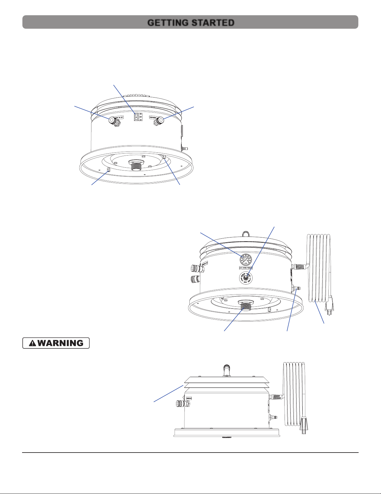
• Handle provided on power head is used only for removal of power head during maintenance.
• Before separation of power head from tank, users must disengage draw latches on tank.
• Do not pull or carry by cord, use cord as a handle, close a door on cord, or pull cord around sharp edges or corners.
• Do not run appliance over cord. Keep cord away from heated surfaces.
• Do not unplug by pulling on cord. To unplug, grasp the plug, not the cord.
• Do not handle plug or appliance with wet hands.
• Do not put any object into openings. Do not use with any opening blocked; keep free of dust, lint, hair, and anything that may
•
•
• Do not
• Connect to a properly grounded outlet only. Refer to “EARTHING/GROUNDING INSTRUCTIONS” on page 3.
• Do not pick up anything that is burning or smoking, such as cigarettes, matches, or hot ashes.
• Do not
• Do not allow to be used as a toy. Close attention necessary when used by or near children.
EARTHING/GROUNDING INSTRUCTIONS
This appliance must be earthed/grounded. If it should malfunction or breakdown, earthing/grounding provides a path of least resistance
conductor and earthing/grounding plug. The plug must be inserted into an appropriate outlet that is properly installed and earthed/grounded in
accordance with all local codes and ordinances.
WARNING
electrician or service person if you are in doubt as to whether the outlet is properly earthed/grounded. Do not modify the plug provided with the
Refer to Name Plate for electrical requirements.
• USA 120 V
This appliance has a earthing/grounding attachment plug that looks like the
plug illustrated in Figure 1. Make sure that the appliance is connected to an
with this appliance.
• International 120 V
This appliance has an IEC 60309 120 V earthing/grounding attachment plug.
Make sure that the appliance is connected to an outlet having the same
• International 220 V – 240 V
This appliance has an IEC 60309 250 V earthing/grounding attachment plug.
Make sure that the appliance is connected to an outlet having the same
IMPORTANT SAFETY INSTRUCTIONS
SAVE THESE INSTRUCTIONS
Figure 1: Earthed/Grounded Outlet and Plug
GL_002
Grounded
Outlet Box
Grounded Outlet
Grounding Pin

Repair or Warranty Contact Clayton Associates, Inc. • 1650 Oak Street • Lakewood, New Jersey 08701 • P.+1-732-363-2100 F.+1-732-364-6084
WGP-0 www.DustlessMadeSimple.com • [email protected]
Page 4
• Designed for general cleanup, housekeeping, and vacuum sanding.
• Dry recovery only.
Do not use this equipment for cleaning or extracting fuel residues from any vehicle or equipment.
Do not use this equipment for cleaning or extracting live sparks or burning embers.
Do not use this equipment in combustible dust or gas atmospheres.
NOTE:
both a power head and an appropriate Clayton vacuum tank. Refer to the instruction manual included with the vacuum tank for
additional information.
PHYSICAL:
Weight....................................................................................................................................................................................TBD lbs (TBD kg)
Dimensions (Diameter x Height) .......................................................................................................................... 17.5 x 12 in (44.5 x 30.5 cm)
Sound Level........................................................................................................................................................................................... 67 dBA
POWER CONSUMPTION:
Power Rating ..............................................................................................................................................................................................2 hp
Power Consumption.............................................................................................................................................................. 13.5 A @ 120 Vac
TBD A @ 220 – 240 Vac
Pressure...................................................................................................................................................................................90 psi (621 kPa)
Flow ....................................................................................................................................................................................Determined by Tool
FILTRATION:
...............................................................................................................................................
............................................................................................................................................................. 95% @ 0.5 micron
PERFORMANCE:
120 Vac
Vacuum Flow.......................................................................................................................................................... 120 CFM (204 SCMH)
Vacuum Suction ..........................................................................................................................................................120 inH
2
O (30 kPa)
220 – 240 Vac
Vacuum Flow.......................................................................................................................................................... 115 CFM (196 SCMH)
Vacuum Suction .......................................................................................................................................................... 115 inH
2
O (29 kPa)
APPLICATIONS & ENVIRONMENTS
WHAT’S IN THE BOX
WGP-0_001
WartHog WGP Power Head
SPECIFICATIONS & REQUIREMENTS

Repair or Warranty Contact Clayton Associates, Inc. • 1650 Oak Street • Lakewood, New Jersey 08701 • P.+1-732-363-2100 F.+1-732-364-6084
WGP-0 www.DustlessMadeSimple.com • [email protected]
Page 5
1. The vacuum power head and the vacuum tank ship in separate boxes.
2. Unbox the vacuum power head.
3. Visually inspect the power head to verify that no parts are missing or damaged.
4. Familiarize yourself with the power head.
5. Power Head Vents:
• NEVER BLOCK THE POWER HEAD VENTS.
• NEVER WRAP THE POWER CORD AROUND THE POWER
HEAD VENTS.
GETTING STARTED
WGP-0_005
Compressed Air
Coupler (Air Out)
Compressed Air
Coupler (Air Out)
HEPA Wire Lock
HEPA Wire Lock
Power Switch
WGP-0_006
Pneumatic Tool
Sync Gauge
Delay Valve
Power Cord
Compressed Air Plug
(Air In)
Filter Adapter
WGC-0_007
Power Head
Vents

Repair or Warranty Contact Clayton Associates, Inc. • 1650 Oak Street • Lakewood, New Jersey 08701 • P.+1-732-363-2100 F.+1-732-364-6084
WGP-0 www.DustlessMadeSimple.com • [email protected]
Page 6
Prepare the vacuum for use.
1.
•
•
• Grasp the sides of the cardboard collar and push it all the way onto the inlet tube.
• Verify the bottom of the collar is past the opening on the underside of the inlet tube.
2.
• Remove the Clayton HEPA timer card from the box and set aside.
• Remove the HEPA cable lock from the box and set aside.
•
3.
•
•
–If it is not, rotate it clockwise until fully seated.
• Refer to the instructions included with the HEPA cable lock to install the cable lock.
4. Attach the power head.
• Position the power head on the tank.
• Rotate the power head so that the power switch on the power head is aligned with
the inlet port on the vacuum tank.
• Latch the power head to the tank.
5.
• Attach the new HEPA timer card with a zip tie (included) to the top handle of the
vacuum.
• Follow the directions on timer card to activate it.
GETTING STARTED
GL_005
Filter Bag
Bottom and top of
Cardboard Bag Collar
Push Cardboard Bag Collar
past this point
Tank Wall
Tank Wall
Inlet Port
aligned with …
Power Switch …
WGP-0_008

Repair or Warranty Contact Clayton Associates, Inc. • 1650 Oak Street • Lakewood, New Jersey 08701 • P.+1-732-363-2100 F.+1-732-364-6084
WGP-0 www.DustlessMadeSimple.com • [email protected]
Page 7
• Compressed air must be clean, dry, and oil free to prevent blockage of the pneumatic system.
•
Compressed Air Plug (Air In)
•
•
•
• Install a new compressed air plug.
Compressed Air Coupler (Air Out)
•
• This coupler provides convenient pass through compressed air for an air tool connected to the vacuum.
•
•
• Install a new compressed air coupler.
COMPRESSED AIR FITTINGS

Repair or Warranty Contact Clayton Associates, Inc. • 1650 Oak Street • Lakewood, New Jersey 08701 • P.+1-732-363-2100 F.+1-732-364-6084
WGP-0 www.DustlessMadeSimple.com • [email protected]
Page 8
Principle of Operation
Pneumatic Tool Sync senses the ow of compressed air to a connected tool and activates the vacuum.
• When the compressed air tool is activated, the compressed air line pressure closes a pneumatic electric relay which activates the
power head.
• The auto system pressure in the relay should be approximately 90 psi while the tool is running.
•
Delay valve.
• When the tool sync pressure reaches approximately 15 psi the relay opens and deactivates the power head.
• The Tool Sync Pressure Gauge helps the user visualize the time delay by displaying the pressure in the pneumatic valve as it drops
from 90 psi to 0 psi.
Requirements
• A compressed air supply must be connected to the Compressed Air Plug (Air In) on the power head.
• The tool must draw its compressed air from a Compressed Air Coupler (Air Out) on the power head.
• Compressed air must be clean, dry, and oil free to prevent blockage of the pneumatic system.
•
1. Attach the compressed air line source to the vacuum.
• Verify the power switch on the vacuum is in the OFF position.
• Connect one end of the compressed air line to a compressed air source.
• Connect the other end of the compressed air line to the Compressed Air Plug (Air In) on the vacuum head.
2. Attach the compressed air tool.
• Insert the compressed air line plug into a Compressed Air Coupler (Air Out) on the power head.
the airline has been connected.
• Connect the compressed air line coupler to the tool’s compressed air plug/input.
3. Test Pneumatic Tool Sync.
• Toggle the power switch on the vacuum to the AUTO position and activate the air tool.
• The power head will activate.
• Deactivate the air tool.
• The vacuum will deactivate after a short delay.
4.
The Shut O Delay is preset at the factory to approximately 5 seconds.
•
•
• Toggle the power switch on the vacuum to the AUTO position and activate the air tool.
• The vacuum will power on.
• Deactivate the air tool.
• The vacuum will remain running.
•
Gauge begins to drop.
• When the tool sync pressure reaches approximately 15 psi the relay opens and
deactivates the power head.
• Continue to test Pneumatic Tool Sync by activating the compressed air tool.
•
•
delay, tighten the jam nut by rotating it clockwise to lock the valve in place.
5. Multiple Tools
• Pneumatic Tool Sync will work with one or two tools simultaneously.
PNEUMATIC TOOL SYNC
GL_008
Jam Nut
Delay Valve

Repair or Warranty Contact Clayton Associates, Inc. • 1650 Oak Street • Lakewood, New Jersey 08701 • P.+1-732-363-2100 F.+1-732-364-6084
WGP-0 www.DustlessMadeSimple.com • [email protected]
Page 9
1. Connect the compressed air source.
• Verify the power switch on the vacuum is in the OFF position.
• Connect a compressed air line coupler to the Compressed Air Plug (Air In) on the power head.
• Connect the other end of the compressed air line to the compressed air source.
2. Attach a vacuum hose or combination air/vacuum work hose.
• Open the Inlet Port on the vacuum tank.
• Insert the metal sleeve of the vacuum hose into the Inlet Port on the vacuum tank.
3. Attach the compressed air output hose(s).
• When using a combination air/vacuum work hose, the compressed air output hose is part of the work hose assembly.
•
the airline has been connected.
4. Attach a tool (optional).
•
been connected.
5. Plug the power head/vacuum into an appropriate outlet.
Activate the vacuum.
• Pneumatic Tool Sync Mode:
activated.
–Toggle the Power Switch to the AUTO position for Pneumatic Tool Sync.
•
–Toggle the power switch to the ON position.
BEFORE EACH USE

Repair or Warranty Contact Clayton Associates, Inc. • 1650 Oak Street • Lakewood, New Jersey 08701 • P.+1-732-363-2100 F.+1-732-364-6084
WGP-0 www.DustlessMadeSimple.com • [email protected]
Page 10
1. Safe the vacuum.
• Disconnect the vacuum from the power source.
• Remove all tools and hoses from the vacuum.
2. Remove the power head.
• Unlatch the power head from the tank.
•
•
3.
•
• Holding your hand over the opening on the bag, lift the bag out of the tank.
• Dispose of the bag according to company policy.
4.
•
•
• Grasp the sides of the cardboard collar and push it all the way onto the inlet tube.
• Verify the bottom of the collar is past the opening on the underside of the inlet tube.
5.
•
•
–If it is not, rotate it clockwise until fully seated.
Replace the power head.
• Position the power head on the tank.
• Rotate the power head so that the power switch on the power head is aligned with the inlet port on the vacuum tank.
• Latch the power head to the tank.
BAG FILTER CHANGE
GL_005
Tank Wall
Tank Wall
Bottom and top of
cardboard bag collar
Push cardboard bag
collar past this point
Filter Bag

Repair or Warranty Contact Clayton Associates, Inc. • 1650 Oak Street • Lakewood, New Jersey 08701 • P.+1-732-363-2100 F.+1-732-364-6084
WGP-0 www.DustlessMadeSimple.com • [email protected]
Page 11
1. Safe the vacuum.
• Disconnect the vacuum from the power source.
• Remove all tools and hoses from the vacuum.
2. Remove the power head.
• Unlatch the power head from the tank.
•
•
3.
•
• Find the seam and carefully peel the Velcro apart.
•
4.
•
•
•
5.
•
•
–If it is not, rotate it clockwise until fully seated.
Replace the power head.
• Position the power head on the vacuum tank.
• Rotate the power head so that the power switch on the power head is aligned with the inlet port on the vacuum tank.
• Latch the power head to the tank.
PRE‑FILTER CHANGE

Repair or Warranty Contact Clayton Associates, Inc. • 1650 Oak Street • Lakewood, New Jersey 08701 • P.+1-732-363-2100 F.+1-732-364-6084
WGP-0 www.DustlessMadeSimple.com • [email protected]
Page 12
Never attempt to clean
the HEPA lter as this will damage it.
1. Safe the vacuum.
• Disconnect the vacuum from the power source.
• Remove all tools and hoses from the vacuum.
2. Remove the power head.
• Unlatch the power head from the vacuum tank.
•
•
3.
• Remove the Clayton HEPA timer card from the box and set aside.
• Remove the HEPA cable lock from the box and set aside.
•
4.
• Holding the power head on its side cut the HEPA cable lock and remove it.
•
•
5. Install a new HEPA Filter.
•
•
–If it is not, rotate it clockwise until fully seated.
• Refer to the instructions included with the HEPA cable lock to install the cable lock.
Replace the power head.
• Carefully position the power head on the vacuum tank.
• Rotate the power head so that the power switch on the power head is aligned with the inlet port on the vacuum tank.
• Latch the power head to the vacuum tank.
7.
• Remove the old HEPA timer card from the power head.
• Attach the new HEPA timer card with a zip tie (included) to the top handle of the vacuum.
• Follow the directions on the timer card to activate.
HEPA FILTER CHANGE

Repair or Warranty Contact Clayton Associates, Inc. • 1650 Oak Street • Lakewood, New Jersey 08701 • P.+1-732-363-2100 F.+1-732-364-6084
WGP-0 www.DustlessMadeSimple.com • [email protected]
Page 13
603-WGP-0 (Sheet 1 of 5)
ILLUSTRATED PARTS BREAKDOWN
Seq Item No Description
1 350-023 Strain Relief For 20 Amp Cord
2 605-310A HH Vac Head Handle Cap SS Black
3 605-310D HH Vac Head Exhaust Bafe SS Black
4 605-310E WGP Vac Enclosure Auto-Air 120V SS Black
5 900-143N515P-30 Cord 14/3 15A Cord Lock Plug 30ft Yel
6 900-M14R3 Molex Receptacle, 14 ga, 3 Position
7 900-M14S Molex Socket Terminal, 14 ga
8 900-SW-SPDT-01 Switch Rocker Rect 20A 120V SPDT On-Off-On Black
9 918-04BH Bulkhead Adapter, Brass, 1/4in.
10 924-04CV Check Valve, 1/4 MNPT
11 930-027 Handle, Carry, Flex Rubber
12 940-011 Fitting Coupler 1/4in Hiow x 1/4 MNPT
13 940-016 Fitting Plug 1/4in Hiow x 1/4in MNPT
14 FE103212-HZSM-Z Hex Standoff, 10-32 MF x 3/4 in SS
15 NE10320608-HNSZ Nut 10-32 Nylon Lock SS Short
16 RE0620-SDSSS-Z Rivet Blind 3/16 x 0.625 Sealed SS (.251-.375)
17 SE103206-XPSM-Z Screw 10-32 x 3/8in SS TORX
18 WE133203-RFS-Z Washer .203ID x .500OD .047H Round Stainless Steel
19 WE481803-RZSZ Shim .750 ID x 1.125 OD x .048 Round Stainless
WGP-0_012
1
7
11
16
2
6
12
17
3
8
13
18
4
9
14
14 19
5
10
15

ILLUSTRATED PARTS BREAKDOWN
Repair or Warranty Contact Clayton Associates, Inc. • 1650 Oak Street • Lakewood, New Jersey 08701 • P.+1-732-363-2100 F.+1-732-364-6084
WGP-0 www.DustlessMadeSimple.com • [email protected]
Page 14
ILLUSTRATED PARTS BREAKDOWN
603-WGP-0 (Sheet 2 of 5)
Seq
Item No Description
1 600-A276T Auto System Flow Sensor Valve Threaded
2 900-033 Faston Cap .187 Tab
3 900-SW-SPST-03 Switch Pneumatic Relay 100PSI 15A 120V
4 922-T.25GN 1/4 in OD. Nylon Tubing Green
5 922-T.50BK Tubing, 1/2 OD, High Temp per ft
6 924-04FC-01 Alpha Flow Control Valve
7 925-P24R160-01 Gauge Pressure 1.5in 0-160 PSI Panel Mount
8 927-04FA-02 Female Adapt, 1/4 PC x 1/8 FNPT
9 927-04L-02 PC Elbow 1/8 MNPT x 1/4 Tube
10 927-04L-02F FTG Elbow 1/8 FNPT To 1/4 PC
11 927-04T Tee, 1/4 PC
12 927-08L-04 FTG Elbow 1/2 PC To 1/4 MNPT
13 927-08L-04F FTG Elbow 1/2PC To 1/4FNPT
14 927-08MA-04 1/2 PC x 1/4 MPT Straight FTG
15 927-08Y Union Y, 1/2PC
1
2
3
4
5
6
7
8
9
9
9
10
11
12
12
13
13
14
15
WGP-0_014

Repair or Warranty Contact Clayton Associates, Inc. • 1650 Oak Street • Lakewood, New Jersey 08701 • P.+1-732-363-2100 F.+1-732-364-6084
WGP-0 www.DustlessMadeSimple.com • [email protected]
Page 15
ILLUSTRATED PARTS BREAKDOWN
603-WGP-0 (Sheet 3 of 5)
WGP-0_013
1
2
3
4
5
Seq Item No Description
1
911-803-1 Handle Cap Sound Control Foam
2
911-803-2 Exhaust Bafe Sound Control Foam
3
911-803-3 Enclosure Top Sound Control Foam
4
911-803-4 Base Ring Sound Control Foam
5
911-803-6 Enclosure Foam 1 Sound Control
5
911-803-7 Enclosure Foam 2 Sound Control
5
911-803-8 Enclosure Foam 3 Sound Control

ILLUSTRATED PARTS BREAKDOWN
Repair or Warranty Contact Clayton Associates, Inc. • 1650 Oak Street • Lakewood, New Jersey 08701 • P.+1-732-363-2100 F.+1-732-364-6084
WGP-0 www.DustlessMadeSimple.com • [email protected]
Page 16
ILLUSTRATED PARTS BREAKDOWN
603-WGP-0 (Sheet 4 of 5)
Seq Item No Description
1 600-A108-120 Motor Assembly 120V
2 601-021 Filter Adapter, WartHog
3 601-121 Mesh Disc, 3 in Diameter
4 605-310B16 HH Vac Head Base 16in SS Black
5 911-011 Gasket, Filter Adapter
6 911-Q6600-220T Conical Motor Gasket Silica Gel
7 FE103208-HZSM-B Hex Standoff, 10-32 MF x 1/2 SS With Bore
8 NE10320615-HNSZ Nut, 10-32 Nylon Lock, SS, High
9 NE16201420-HNSZ Nut 1/4-20 Hex Lock SS
10 SE162005-PPSM-Z Screw, 1/4-20 x 5/16 PH, SS
11 SE162064-HHSM-Z Screw 1/4-20 x 4in SS Hex
12 600-WF-1364F Washer Fiber 13/64 ID x 3/8OD
13 900-WH004 Wiring Harness, WGP Pneumatic Relay
14 NE10320608-HNSZ Nut 10-32 Nylon Lock SS Short
WGP-0_009
1
4
7
10
2
5
8
11
3
6
9
12
WGP-0_010
13
14

Repair or Warranty Contact Clayton Associates, Inc. • 1650 Oak Street • Lakewood, New Jersey 08701 • P.+1-732-363-2100 F.+1-732-364-6084
WGP-0 www.DustlessMadeSimple.com • [email protected]
Page 17
ILLUSTRATED PARTS BREAKDOWN
603-WGP-0 (Sheet 5 of 5)
Seq Item No Description
1 600-Q6600-220T Motor Bypass 120V 13.5A 2HP 120CFM
2 605-310C HH Vac Head Motor Collar SS
3 911-04G08 Grommet 7/32 ID, 1/2 OD
4 911-803-5 Motor Plate Sound Control Foam
5 SE101212-PPSS-Z Screw, Sheet Metal, #10 X .750, Phillips, SS
6 WE133203-RFS-Z Washer .203ID X .500OD .047H Round Stainless Steel
WGP-0_011
4
1
5
2
6
3

Repair or Warranty Contact Clayton Associates, Inc. • 1650 Oak Street • Lakewood, New Jersey 08701 • P.+1-732-363-2100 F.+1-732-364-6084
WGP-0 www.DustlessMadeSimple.com • [email protected]
Page 18
Warranty Terms
Clayton Associates, Inc. guarantees its manufactured products against defects in materials or workmanship and will either repair or replace
all parts that prove defective under normal use during the lifetime of the products. The warranty period shall commence from the date of paid
invoice.
This warranty does not cover (a) repairs due to normal wear, accident, neglect, misuse, or use other than as indicated in the instruction booklet
(b) products manufactured by third parties and distributed by Clayton (c) wear items such as bearings, rotor blades, regulators, valve stems,
levers, shrouds, guards, O‑rings, seals, gaskets, motor brushes, and other wearable parts.
Repair within the Continental US
associated with returning the products for repair to a Clayton selected service location and repair the product at no charge. Clayton personnel
will determine the best way to repair the product.
Past 90 days, Clayton will provide parts to the customer’s site at no charge or the customer may ship the product to a Clayton selected service
location at customer’s expense and Clayton will repair the product at no charge and provide return shipping.
Repair Outside the Continental US
Clayton will provide parts to the customer’s site at no charge or the customer may ship the product to a Clayton selected service location at
customer’s expense and Clayton will repair the product at no charge and provide return shipping.
Limitation of Liability
or its failure to operate.
Clayton Associates, Inc. makes no other warranty or representation of any kind, except that of title, and all other warranties, express or implied,
LIMITED LIFETIME WARRANTY TERMS AND CONDITIONS

Brad Clayton
President
Clayton Associates, Inc.
Repair or Warranty Contact Clayton Associates, Inc. • 1650 Oak Street • Lakewood, New Jersey 08701 • P.+1-732-363-2100 F.+1-732-364-6084
WGP-0 www.DustlessMadeSimple.com • [email protected]
Page 19
Clayton Associates, Inc. of 1650 Oak Street, Lakewood New Jersey 08701 U.S.A. declare on our own responsibility that the
Industrial HEPA Filtered, Electrically Powered Vacuum Cleaners and Accessories for Dry Recovery
•
WGX‑XXXX‑0, WGP‑XXXX‑0, WTX‑XXXX‑0, WTP‑XXXX‑0
WGX‑XXXX‑1, WGP‑XXXX‑1, WTX‑XXXX‑1, WTP‑XXXX‑1
• 115G,115T,205G, 205T, 215G, 215T
• With serial numbers ranging from WH0000001 through WH9999999
•
• The Electromagnetic Compatibility Directive 2004/108/EC
• EN ISO 12100:2010‑11
•
•
collection of hazardous dusts
• EN 55014‑1:2017
• EN 55014‑2:2015
Way, Wrexham Industrial Estate, Wrexham, LL13 9UZ, United Kingdom.
File Number: 18FILE0423
Subject to use for the purpose for which it was designed in accordance with relevant standards and with the manufacturer’s
EC DECLARATION OF CONFORMITY

Brad Clayton
President
Clayton Associates, Inc.
Repair or Warranty Contact Clayton Associates, Inc. • 1650 Oak Street • Lakewood, New Jersey 08701 • P.+1-732-363-2100 F.+1-732-364-6084
WGP-0 www.DustlessMadeSimple.com • [email protected]
Page 20
EC DECLARATION OF CONFORMITY
Clayton Associates, Inc. of 1650 Oak Street, Lakewood New Jersey 08701 U.S.A. declare on our own responsibility that the
Industrial HEPA Filtered, Electrically Powered Vacuum Cleaners
•
WGX‑XXXX‑0, WGP‑XXXX‑0, WTX‑XXXX‑0, WTP‑XXXX‑0
WGX‑XXXX‑1, WGP‑XXXX‑1, WTX‑XXXX‑1, WTP‑XXXX‑1
• 115G,115T,205G, 205T, 215G, 215T
• With serial numbers ranging from WH0000001 through WH9999999
Test Procedure:
• The test was performed using an aerosol generator and a photometer.
•
•
Test Results:
•
•
Declaration:
•
Other manuals for Warthog WGP Series
1
This manual suits for next models
4
Table of contents
Other Clayton Vacuum Cleaner manuals

Clayton
Clayton WTP-107T-4 Guide

Clayton
Clayton WartHog WGX Series Guide

Clayton
Clayton Scorpion SC-100 Series Guide

Clayton
Clayton WGX-107G-0 Troubleshooting guide

Clayton
Clayton Warthog WGP Series Guide

Clayton
Clayton 603-105T Guide

Clayton
Clayton Hornet 500-400 Guide

Clayton
Clayton WartHog 603-105G Guide

Clayton
Clayton Warthog WTX Series Guide

Clayton
Clayton WartHog WTX-107T-0 Guide