Clayton Warthog WGP Series Guide

Scan this QR code for
online instructions and
documentation, or visit
www.ClaytonHowTo.com
October 2019
WARNING
SAFETY LEGEND
Hearing protection is recommended when
operating this equipment.
Respiratory protection is recommended when
operating this equipment.
Read and understand operator’s manual before
using this equipment.
Eye protection is required when operating
this equipment.
WARNING WARNING
WARNING
WARNING
WARNING
•
A HEPA Filter must be installed in this vacuum at all times
•
If this vacuum is used to collect hazardous material, appropriate personal protective equipment may be required
•
Any alteration to this equipment by a third party will nullify its warranty
Safety – Operation – Maintenance
Keep this document in a safe place
Read and understand this manual before operating your vacuum
Warthog WGP
Industrial Vacuum 120V / 220V with Pneumatic Tool Sync
Models with Prex: WGP-115G-0, WGP-205G-0, WGP-215G-0
• Designed for general cleanup, housekeeping, vacuum sanding
• Dry Recovery Only

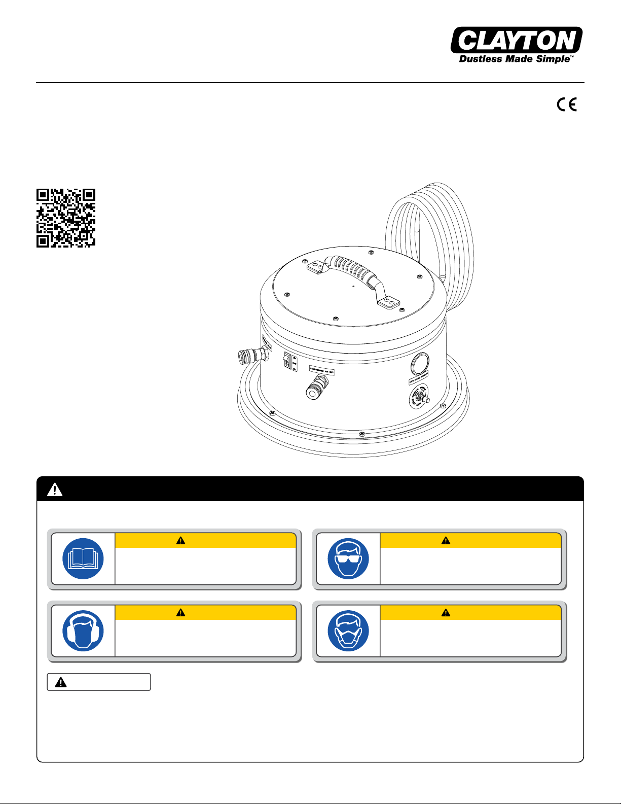
IMPORTANT SAFETY INSTRUCTIONS
READ ALL INSTRUCTIONS BEFORE USING THIS APPLIANCE
When using an electrical appliance, basic precautions should always be followed, including the following:
WARNING
• To reduce the risk of re, electric shock, or injury:
• Do not leave appliance when plugged in. Unplug from outlet when not in use and before servicing.
• This unit is to be used only indoors and in a dry location.
• Use only as described in this manual. Use only manufacturer’s recommended attachments.
• Do not use with damaged cord or plug. If appliance is not working as it should, has been dropped, damaged, left outdoors,
or dropped into water, return it to a service center.
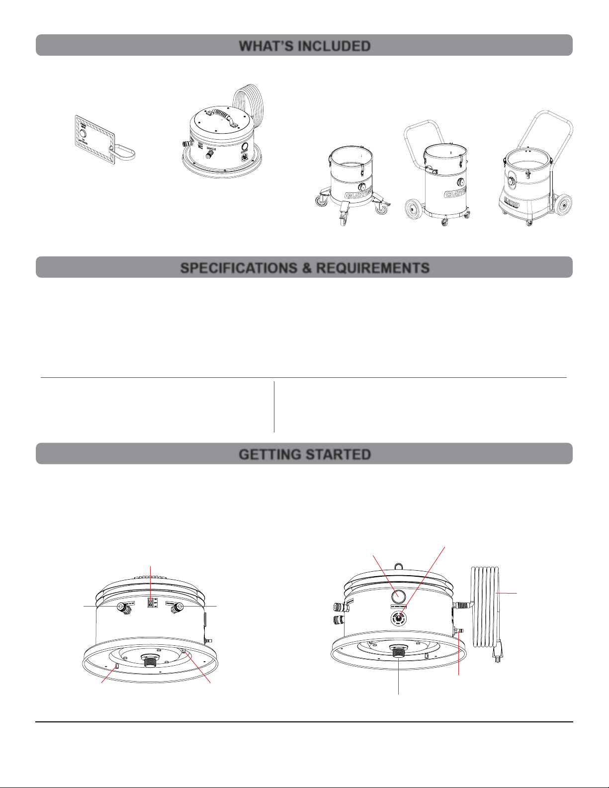
• Handle provided on power head is used only for removal of power head during maintenance.
•Before separation of power head from tank, users must disengage draw latches on tank.
• Do not pull or carry by cord, use cord as a handle, close a door on cord, or pull cord around sharp edges or corners.
• Do not run appliance over cord. Keep cord away from heated surfaces.
• Do not unplug by pulling on cord. To unplug, grasp the plug, not the cord.
• Do not handle plug or appliance with wet hands.
• Do not put any object into openings. Do not use with any opening blocked; keep free of dust, lint, hair, and anything that may
reduce air ow.
• Keep hair, loose clothing, ngers, and all parts of body away from openings and moving parts.
• Turn off all controls before unplugging.
• Do not use to pick up ammable or combustible liquids, such as gasoline, or use in areas where they may be present.
• Connect to a properly grounded outlet only. See Grounding Instructions.
• Do not pick up anything that is burning or smoking, such as cigarettes, matches, or hot ashes.
• Do not use without all lters in place.
• Do not allow to be used as a toy. Close attention necessary when used by or near children.
SAVE THESE INSTRUCTIONS
EARTHING/GROUNDING INSTRUCTIONS
This appliance must be earthed/grounded. If it should malfunction or breakdown, earthing/grounding provides a path of least resistance
for electric current to reduce the risk of electric shock. This appliance is equipped with a cord having an equipment-earthing/grounding
conductor and earthing/grounding plug. The plug must be inserted into an appropriate outlet that is properly installed and earthed/grounded
in accordance with all local codes and ordinances.
WARNING – Improper connection of the equipment-earthing/grounding conductor can result in a risk of electric shock. Check with a
qualied electrician or service person if you are in doubt as to whether the outlet is properly earthed/grounded. Do not modify the plug
provided with the appliance – if it will not t the outlet, have a proper outlet installed by a qualied electrician.
See Power Head Name Plate for electrical requirements
USA 120V
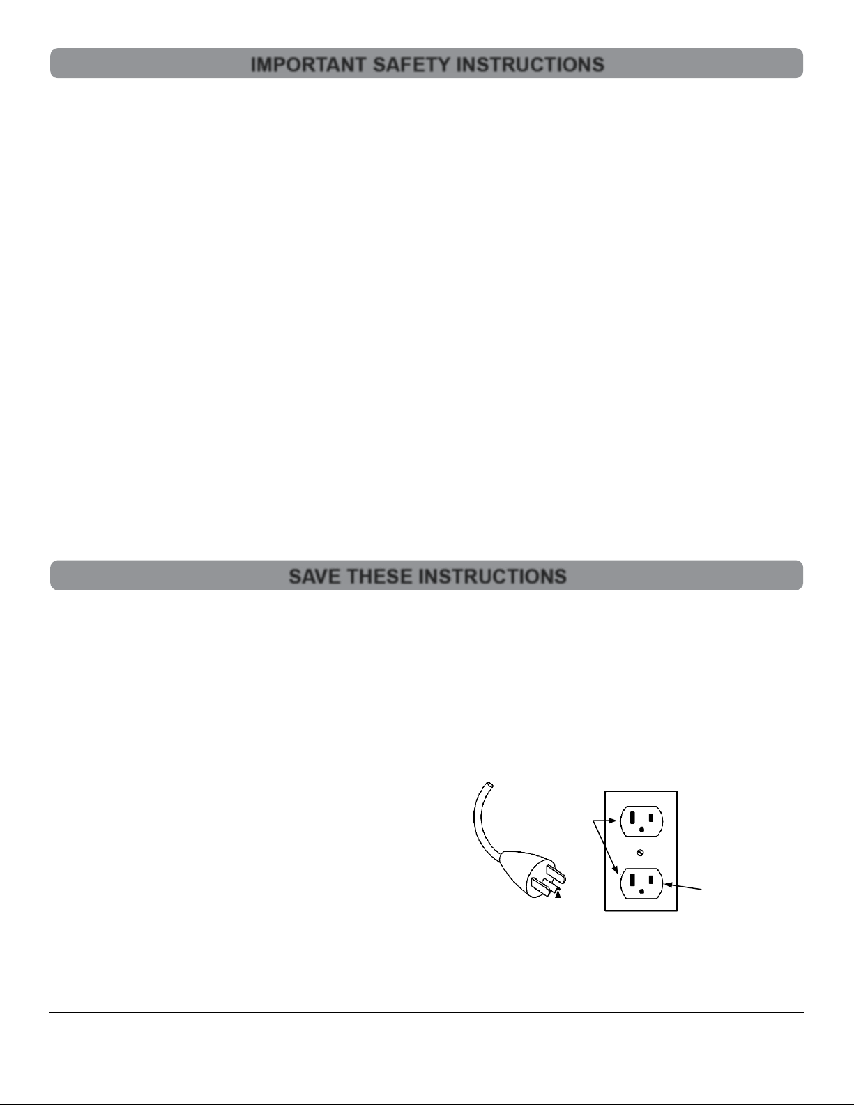
This appliance has a earthing/grounding attachment plug that looks
like the plug illustrated in Figure 1. Make sure that the appliance is
connected to an outlet having the same conguration as the plug.
No adaptor should be used with this appliance.
International 120V
This appliance has a IEC 60309 125V earthing/grounding attachment plug.
Make sure that the appliance is connected to an outlet having the same
conguration as the plug. No adaptor should be used with this appliance
International 220-240V
This appliance has a IEC 60309 250V earthing/grounding attachment plug.
Make sure that the appliance is connected to an outlet having the same
conguration as the plug. No adaptor should be used with this appliance.
Earthed/Grounded
Outlet
Repair or Warranty Contact Clayton Associates, Inc. • 1650 Oak Street • Lakewood, New Jersey 08701 • P.+1-732-363-2100 F.+1-732-364-6084
Page 2
Figure 1: Earthed/Grounded Outlet and Plug
Earthed/Grounded
Outlet Box

TABLE OF CONTENTS
APPLICATIONS & ENVIRONMENTS
• Designed for general cleanup and housekeeping
• Dry Recovery Only
Do not use this equipment for cleaning or extracting fuel residues from any vehicle or equipment
Do not use this equipment for cleaning or extracting live sparks or burning embers
Do not use this equipment for use in combustible dust or gas atmospheres
WARNING
Important Safety Instructions.............................................................................................. 2
Save These Instructions ..................................................................................................... 2
Table of Contents................................................................................................................ 3
Applications & Environments.............................................................................................. 3
What’s Included .................................................................................................................. 4
Specications & Requirements........................................................................................... 4
Getting Started ................................................................................................................... 4
Compressed Air Fittings ..................................................................................................... 5
Pneumatic Tool Sync .......................................................................................................... 6
Before Each Use ................................................................................................................ 7
Bag Filter Change............................................................................................................... 8
Pre-Filter Change ............................................................................................................... 9
HEPA Filter Change............................................................................................................ 9
Illustrated Parts Breakdown.............................................................................................. 10
Limited Lifetime Warranty Terms and Conditions .............................................................14
Declaration of Conformity .................................................................................................15
Repair or Warranty Contact Clayton Associates, Inc. • 1650 Oak Street • Lakewood, New Jersey 08701 • P.+1-732-363-2100 F.+1-732-364-6084
Page 3

603-115G603-205G 603-215G
Repair or Warranty Contact Clayton Associates, Inc. • 1650 Oak Street • Lakewood, New Jersey 08701 • P.+1-732-363-2100 F.+1-732-364-6084
Page 4
WHAT’S INCLUDED
GETTING STARTED
1. The vacuum Power Head and the Vacuum Tank ship in separate boxes
2. Unbox the Vacuum Power Head
3. Visually inspect Power Head to ensure that no parts are missing or damaged
4. Familiarize yourself with the Power Head
Power Cord
Filter Adapter
Pneumatic
Tool Sync Gauge
Pneumatic
Tool Sync Adjustment
Compressed Air Plug
(Air In)
HEPA Wire Lock
Hex Standoff
HEPA Wire Lock
Hex Standoff
Power Switch
Compressed
Air Coupler
(Tool Air Out)
Compressed
Air Coupler
(Tool Air Out)
Clayton Warthog Power Heads ship with the following items:
• Warthog WGP Power Head
• HEPA 12 Month Timer Card
Clayton Vacuum Tanks ship separately and include
Bags, Filters, and other components.
These instructions
asume you have both a Power Head and one of
the following Clayton Vacuum Tanks
SPECIFICATIONS & REQUIREMENTS
Weight ...........................................................................21.7 lbs (9.8 kg)
Dimensions....................................................................17.5 x 17.5 x 12 in (44.5 x 44.5 x 30.5 cm)
HEPA Filter Efciency....................................................99.995% @ 0.3 μm (H14)
Filter Bag Efciency.......................................................95% @ 0.5 micron
Sounds Pressure Level .................................................<70 dBA
Compressed Air Consumption.......................................Determined by Tool
Compressed Air Supply Pressure..................................90-120 PSI (6.2 - 8.3 bar)
120 Volt
Power Consumption ...... 120VAC~ 12.5A
Vacuum Flow ................. 120 CFM (204 SCMH)
Vacuum Suction............. 120 in/H
2
O (30 kPa)
220-240 Volt
Power Consumption ...... 220-240VAC~ 5.5-6A
Vacuum Flow ................. 120 CFM (204 SCMH)
Vacuum Suction............. 120 in/H
2
O (30 kPa)

COMPRESSED AIR FITTINGS
The vacuum has the following Compressed Air Requirements to function properly.
• Compressed air must be clean, dry, and oil free to prevent blockage of the pneumatic system
• Compressed air line and ttings must have a minimum diameter of 1/4in (7mm)
Compressed Air Plug (air in)
• The Vacuum is supplied with a 1/4in (7mm) industrial interchange compressed air plug for connection to your compressed air supply
The Compressed Air Plug may be changed to another nominal 1/4in (7mm) style if required.
• Hold the brass bulkhead tting with a 1in (26mm) open end wrench
• Remove the compressed air plug with either a 9/16in (15mm)deep socket or 9/16in (15mm)open end wrench
• Install a new compressed air plug
Compressed Air Coupler (air out)
• The Vacuum is supplied with two 1/4in (7mm) brass high ow compatible industrial interchange compressed air couplers
• This coupler provides convenient pass through compressed air for an air tool connected to the vacuum
The Compressed Air Coupler may be changed to another nominal 1/4in (7mm) style if required.
• Hold the brass bulkhead tting with a 1in (26mm) open end wrench
• Remove the compressed air coupler with a 3/4in (19mm) open end wrench
• Install a new compressed air coupler
WARNING
Repair or Warranty Contact Clayton Associates, Inc. • 1650 Oak Street • Lakewood, New Jersey 08701 • P.+1-732-363-2100 F.+1-732-364-6084
Page 5
5. Power Head Vents
• NEVER BLOCK THE POWER HEAD VENTS
• NEVER WRAP THE POWER CORD AROUND THE POWER HEAD VENTS
GETTING STARTED
Vents
Preparing the Vacuum for Use
1. Install a Filter Bag
• Unfold and uff a new Filter Bag
• Push the inlet tube into the hole on the cardboard collar of the Filter Bag
• Grasp the sides of the cardboard collar and push it all the way on to the inlet tube
• Ensure the bottom of the collar is past the opening on the underside of the inlet tube
2. Unbox a new HEPA Filter
• Remove the Clayton HEPA Timer Card from the box and set aside
• Remove the HEPA Cable Lock from the box and set aside
• Remove the HEPA Filter from the box and remove from plastic bag
3. Install a new HEPA Filter
• Holding the power head on its side, screw the new HEPA Filter onto the threaded nipple
• Ensure the white inner ring of the HEPA Filter is in contact with the underside of the power head
• If it is not, turn it clockwise until it comes in contact with the underside of the power head
• See the instructions included with the HEPA Cable Lock
4. Attach the Power Head
• Sit the Power Head on the tank
• Rotate the Power Head so that the switch on the Power Head is in line with the inlet port on the vacuum tank
• Latch the Power Head to the tank

PNEUMATIC TOOL SYNC
1. Principle of Operation
Pneumatic tool sync senses the ow of compressed air to a connected tool and activates the vacuum
• When the compressed air tool is activated, the compressed air line pressure closes a pneumatic electric relay which activates the
power head
• The auto system pressure in the relay is approximately 90 psi while the tool is running
• When the compressed air tool is deactivated the pressure will bleed down to 0 psi, at a rate based on the adjustment of the Shutoff
Delay Valve
• When the tool sync pressure reaches approximately 15 psi the relay opens and deactivates the power head
• The tool sync pressure gauge helps the user visualize the time delay by displaying the pressure in the pneumatic electric relay as it
changes from 90 psi to 0 psi
2. Requirements
• A compressed air supply must be connected to the compressed air in plug on the power head
• The tool must draw its compressed air from the compressed air out coupler on the power head
• Compressed air must be clean, dry, and oil free to prevent blockage of the pneumatic system
• Compressed air line and ttings must have a minimum diameter of 1/4in
3. Attach the Compressed Air Line
• Ensure that the power switch on the vacuum is in the off position
• Connect the compressed air line to a compressed air source
• Connect the compressed air line to the compressed air in plug on the vacuum
4. Attach the Compressed Air Tool
• Ensure that the power switch on the vacuum is in the off position
• Connect the tool compressed air line to the compressed air out coupler on the power head
• Connect the tool compressed air line to the compressed air plug on the tool
5. Testing Pneumatic Tool Sync
• Toggle the power switch to the Auto position
• Activate the air tool
• The power head will activate
• Deactivate the air tool
• The vacuum will deactivate after a short delay
6. Adjusting the Pneumatic Tool Sync Shutoff Delay
The Shutoff Delay is factory set to approximately 5 sec
• Loosen the jam nut
• Turn the Shutoff Delay valve clockwise until it stops.
• Toggle the power switch to the Auto position.
• Activate the air tool
• The vacuum will power on
• Deactivate the air tool
• The vacuum will remain running
• Slowly turn the Shutoff Delay valve counterclockwise until the Tool Sync Pressure Gauge begins to drop
• When the Tool Sync Pressure reaches approximately 15 psi the relay opens and deactivates the power head
• Continue to test Pneumatic Tool Sync by activating the compressed air tool
• Adjust the Shutoff Delay Valve until the pressure bleeds down as slow or as fast as required using the tool sync pressure gauge
as a guide
Repair or Warranty Contact Clayton Associates, Inc. • 1650 Oak Street • Lakewood, New Jersey 08701 • P.+1-732-363-2100 F.+1-732-364-6084
Page 6

Repair or Warranty Contact Clayton Associates, Inc. • 1650 Oak Street • Lakewood, New Jersey 08701 • P.+1-732-363-2100 F.+1-732-364-6084
Page 7
BEFORE EACH USE
1. Attach the Vacuum Hose (optional)
• Open the Vacuum Inlet
• Insert the metal sleeve of the vacuum hose into the inlet on the vacuum
2. Attach a Combination Air/Vac Hose (optional)
• Open the Vacuum Inlet
• Insert the metal sleeve of the vacuum hose into the inlet on the vacuum
• Connect the compressed air line to the compressed air coupler on the vacuum
3. Attach the Compressed Air Line (optional)
• Ensure that the power switch on the vacuum is in the off position
• Connect the compressed air line to a compressed air source
• Connect the compressed air line to the compressed air plug on the vacuum
4. Activating the Vacuum
Pneumatic Tool Sync Mode
This vacuum is equipped with Pneumatic Tool Sync (Auto Mode) which activates the vacuum automatically when a compressed air tool is activated.
The pass through compressed air connection is required for Pneumatic Tool Sync operation.
• Toggle the Power Switch to the Auto Position for Pneumatic Tool Sync
Manual On/Off Mode
This vacuum is equipped with Manual Mode (ON Mode) which activates the vacuum when the switch is set to ON
• Toggle the Power Switch to the ON Position

BAG FILTER CHANGE
If this vacuum is used to collect hazardous material, appropriate personal protective equipment may be required.
The bag lter should be replaced then ¾ full
1. Safe the Vacuum
• Disconnect the Vacuum from power source
2. Remove the Power Head
• Unlatch the Power Head from the tank
• Lift the Power Head and attached HEPA lter off the tank by the top handle
• Carefully sit the Power Head on the oor - avoid damaging the HEPA lter
3. Remove the Filter Bag
• Grasp the cardboard collar of the bag lter and slide it off the inlet
• Holding your hand over the opening on the bag, lift the bag out of the tank
• Dispose of the bag according to your company policy
4. Install a Filter Bag
• Unfold and uff a new Filter Bag
• Push the inlet tube into the hole on the cardboard collar of the lter bag
• Grasp the sides of the cardboard collar and push it all the way on to the inlet tube
• Ensure the bottom of the collar is past the opening on the underside of the inlet tube
5. Ensure the HEPA Filter is sealed
• Holding the power head on its side, look at the HEPA Filter
• Ensure the white inner ring of the HEPA Filter is in contact with the underside of the power head
• If it is not, turn it clockwise until it comes in contact with the underside of the power head
6. Replace the Power Head
• Sit the Power Head on the tank
• Rotate the Power Head so that the switch on the Power Head is in line with the inlet port on the vacuum tank
• Latch the Power Head to the tank
Repair or Warranty Contact Clayton Associates, Inc. • 1650 Oak Street • Lakewood, New Jersey 08701 • P.+1-732-363-2100 F.+1-732-364-6084
Page 8

HEPA FILTER CHANGE
If this vacuum is used to collect hazardous material, appropriate personal protective equipment may be required.
The HEPA lter should be replaced when it is damaged, clogged, or when the HEPA timer card has reached
12 months.
1. Safe the Vacuum
• Disconnect the Vacuum from power source
2. Remove the Power Head
• Unlatch the Power Head from the tank
• Lift the Power Head and attached HEPA lter off the tank by the top handle
• Carefully sit the Power Head on the oor - avoid damaging the HEPA lter
3. Unbox a new HEPA Filter
• Remove the Clayton HEPA Timer Card from the box and set aside
• Remove the HEPA Cable Lock from the box and set aside
• Remove the HEPA Filter from the box and remove from plastic bag
4. Remove the HEPA Filter
• Holding the Power Head on its side cut the HEPA Cable Lock and remove
• Unscrew the HEPA Filter
• Dispose of the HEPA Filter according to your company policy
5. Install a new HEPA Filter
• Holding the power head on its side, screw the new HEPA Filter onto the threaded nipple
• Ensure the white inner ring of the HEPA Filter is in contact with the underside of the power head
• If it is not, turn it clockwise until it comes in contact with the underside of the power head
• See the instructions included with the HEPA Cable Lock
6. Replace the Power Head
• Sit the Power Head on the tank
• Rotate the Power Head so that the switch on the Power Head is in line with the inlet port on the vacuum tank
• Latch the Power Head to the tank
7. Activate the HEPA Filter Timer
• Remove the old HEPA timer card from the power head
• Attach the new HEPA timer card with a zip tie (included) to the top handle of the vacuum
• Follow the directions on Timer Card to activate
PRE-FILTER CHANGE
If this vacuum is used to collect hazardous material, appropriate personal protective equipment may be required.
The pre-lter should be replaced if clogged or visibly dirty
1. Safe the Vacuum
• Disconnect the vacuum from power source
2. Remove the Power Head
• Unlatch the Power Head from the tank
• Lift the Power Head and attached HEPA lter off the tank by the top handle
• Carefully sit the Power Head on the oor - avoid damaging the HEPA lter
3. Remove the Pre-Filter
• The Pre-Filter is wrapped around the HEPA lter and secured with Velcro
• Find the seam and carefully peel the Velcro apart
• Dispose of the Pre-Filter according to your company policy
4. Install a new Pre-Filter
• Unfold a new Pre-Filter and remove the thin Velcro cover strip from the Velcro hooks
• Wrap the Pre-Filter tightly around the HEPA lter
• Secure the Pre-Filter by adhering the Velcro hooks to the side of the Pre-Filter
Repair or Warranty Contact Clayton Associates, Inc. • 1650 Oak Street • Lakewood, New Jersey 08701 • P.+1-732-363-2100 F.+1-732-364-6084
Page 9

ILLUSTRATED PARTS BREAKDOWN
603-WGP-0
SEQ ITEM NO DESCRIPTION
1 600-A108-120 MOTOR ASSEMBLY 120V
2 601-021 FILTER ADAPTER, WARTHOG
3 601-121 MESH DISC, 3 IN DIAMETER
4 605-310B16 HH VAC HEAD BASE 16IN SS BLACK
5 900-WH004 WIRING HARNESS, WGP PNEUMATIC RELAY
6 911-011 GASKET, FILTER ADAPTER
7 911-Q6600-220T CONICAL MOTOR GASKET SILICA GEL
8 FE103208-HZSM-B HEX STANDOFF, 10-32 MF X 1/2 SS WITH
BORE
9NE10320608-HNSZ NUT 10-32 NYLON LOCK SS SHORT
10 NE10320615-HNSZ NUT, 10-32 NYLON LOCK, SS, HIGH
11 NE16201420-HNSZ NUT 1/4-20 HEX LOCK SS
12 SE162005-PPSM-Z SCREW, 1/4-20 X 5/16 PH, SS
13 SE162064-HHSM-Z SCREW 1/4-20 X 4IN SS HEX
14 600-WF-1364F WASHER FIBER 13/64 ID X 3/8OD
Repair or Warranty Contact Clayton Associates, Inc. • 1650 Oak Street • Lakewood, New Jersey 08701 • P.+1-732-363-2100 F.+1-732-364-6084
Page 10
10
12
13 8
14
4
3
7
1
5
11
6
2
WIRING HARNESS REPRESENTATIVE
ACTUAL HARNESS MAY DIFFER IN APPEARANCE
9

ILLUSTRATED PARTS BREAKDOWN
603-WGP-0
SEQ ITEM NO DESCRIPTION
1 350-023 STRAIN RELIEF FOR 20 AMP CORD
2 605-310A HH VAC HEAD HANDLE CAP SS BLACK
3 605-310D HH VAC HEAD EXHAUST BAFFLE SS BLACK
4 605-310E WGP ENCLOSURE GENERAL CLEANUP AUTO-P ELEC SS
BLACK
5 900-143N515P-30 CORD 14/3 15A CORD LOCK PLUG 30FT YEL
6 900-M14R3 MOLEX RECETACLE, 14 GA, 3 POSITION
7 900-M14S MOLEX SOCKET TERMINAL, 14 GA
8 900-SW-SPDT-01 SWITCH ROCKER RECT 20A 120V SPDT ON-OFF-ON BLACK
9918-04BH BULKHEAD ADAPTER, BRASS, 1/4IN.
10 924-04CV CHECK VALVE, 1/4 MNPT
11 930-027 HANDLE, CARRY, FLEX RUBBER
12 940-011 FITTING COUPLER 1/4IN HIFLOW X 1/4 MNPT
13 940-016 FITTING PLUG 1/4IN HIFLOW X 1/4IN MNPT
14 FE103212-HZSM-Z HEX STANDOFF, 10-32 MF X 3/4 IN SS
15 NE10320608-HNSZ NUT 10-32 NYLON LOCK SS SHORT
16 RE0620-SDSSS-Z RIVET BLIND 3/16 X 0.625 SEALED SS (.251-.375)
17 SE103206-XPSM-Z SCREW 10-32 X 3/8IN SS TORX
18 WE133203-RFS-Z WASHER .203ID X .500OD .047H ROUND STAINLESS STEEL
19 WE481831-RZSZ SHIM .750 ID X 1.125 OD X .048 ROUND STAINLESS
Repair or Warranty Contact Clayton Associates, Inc. • 1650 Oak Street • Lakewood, New Jersey 08701 • P.+1-732-363-2100 F.+1-732-364-6084
Page 11
4
9
8
9
3
2
1
6 7
5
9
15
12
10
14
14
17
16
18 11
19
13
12

ILLUSTRATED PARTS BREAKDOWN
603-WGP-0
SEQ ITEM NO DESCRIPTION
1 911-803-1 HANDLE CAP SOUND CONTROL FOAM
2 911-803-2 EXHAUST BAFFLE SOUND CONTROL FOAM
3 911-803-3 ENCLOSRE TOP SOUND CONTROL FOAM
4 911-803-5 MOTOR PLATE SOUND CONTROL FOAM
5 911-803-4 BASE RING SOUND CONTROL FOAM
6 911-803-6 ENCLOSURE FOAM 1 SOUND CONTROL
6 911-803-7 ENCLOSURE FOAM 2 SOUND CONTROL
6 911-803-8 ENCLOSURE FOAM 3 SOUND CONTROL
Repair or Warranty Contact Clayton Associates, Inc. • 1650 Oak Street • Lakewood, New Jersey 08701 • P.+1-732-363-2100 F.+1-732-364-6084
Page 12
1
2
3
4
5
6

ILLUSTRATED PARTS BREAKDOWN
603-WGP-0
SEQ ITEM NO DESCRIPTION
1 600-A276T AUTO SYSTEM FLOW SENSOR VALVE THREADED
2 900-SW-SPST-03 SWITCH PNEUMATIC RELAY 100PSI 15A 120V
3 922-T.25GN 1/4 IN OD. NYLON TUBING GREEN
4 922-T.50BK TUBING, 1/2 OD, HIGH TEMP PER FT
5 924-04FC-01 ALPHA FLOW CONTROL VALVE
6 925-P24R160-01 GAUGE PRESSURE 1.5IN 0-160 PSI PANEL MOUNT
7 927-04L-02 PC ELBOW 1/8 MNPT X 1/4 TUBE
8 927-04L-02F FTG ELBOW 1/8 FNPT TO 1/4 PC
9927-04T TEE, 1/4 PC
10 927-08L-04 FTG ELBOW 1/2 PC TO 1/4 MNPT
11 927-08L-04F FTG ELBOW 1/2PC TO 1/4FNPT
12 927-08MA-04 1/2 PC X 1/4 MPT STRAIGHT FTG
13 927-08Y UNION Y, 1/2PC
Repair or Warranty Contact Clayton Associates, Inc. • 1650 Oak Street • Lakewood, New Jersey 08701 • P.+1-732-363-2100 F.+1-732-364-6084
Page 13
13
12
11
11
10
10
2
8
6
9
3
1
7
7
4
5
7

LIMITED LIFETIME WARRANTY TERMS AND CONDITIONS
Warranty Terms
Clayton Associates, Inc. guarantees its manufactured products against defects in materials or workmanship and will either repair or replace
all parts that prove defective under normal use during the lifetime of the products. The warranty period shall commence from the date
of paid invoice.
This warranty does not cover (a) repairs due to normal wear, accident, neglect, misuse, or use other than as indicated in the instruction
booklet (b) products manufactured by third parties and distributed by Clayton (c) wear items such as bearings, rotor blades, regulators,
valve stems, levers, shrouds, guards, O-rings, seals, gaskets, motor brushes, and other wearable parts.
Repair within the Continental US
During the rst 90 days of the warranty period, Clayton will provide parts and labor to the customer’s site at no charge or pay freight
costs associated with returning the products for repair to a Clayton selected service location and repair the product at no charge.
Clayton personnel will determine the best way to repair the product.
Past 90 days, Clayton will provide parts to the customer’s site at no charge or the customer may ship the product to a Clayton selected
service location at customer’s expense and Clayton will repair the product at no charge and provide return shipping.
Repair Outside the Continental US
Clayton will provide parts to the customer’s site at no charge or the customer may ship the product to a Clayton selected service location at
customer’s expense and Clayton will repair the product at no charge and provide return shipping.
Limitation of Liability
Clayton shall not in any event be liable for any damages, loss of production time or prots, whether based on contract, warranty, negligence,
strict liability or otherwise, including without limitation any consequential, incidental or special damages, arising with respect to the equipment
or its failure to operate.
Clayton Associates, Inc. makes no other warranty or representation of any kind, except that of title, and all other warranties,
express or implied, including warranties of merchantability or tness for any particular purpose, are hereby expressly disclaimed.
Repair or Warranty Contact Clayton Associates, Inc. • 1650 Oak Street • Lakewood, New Jersey 08701 • P.+1-732-363-2100 F.+1-732-364-6084
Page 14

Clayton Associates, Inc. of 1650 Oak Street, Lakewood New Jersey 08701 U.S.A. declare on our own responsibility that the
following equipment:
Industrial HEPA Filtered, Electrically Powered Vacuum Cleaners and Accessories for Dry Recovery
• Vacuum Models (where XXXX is the Tank Model):
WGX-XXXX-0, WGP-XXXX-0, WTX-XXXX-0, WTP-XXXX-0
WGX-XXXX-1, WGP-XXXX-1, WTX-XXXX-1, WTP-XXXX-1
• Tank Models: 115G,115T,205G, 205T, 215G, 215T
• With serial numbers ranging from WH0000001 through WH9999999
Are designed and manufactured in compliance with the essential requirements and other relevant provisions of the following
applicable directives:
• Machinery Directive 2006/42/EC
• The Electromagnetic Compatibility Directive 2004/108/EC
Compliance has been obtained by application of the following standards:
• EN ISO 12100:2010-11
• EN 60335-1:2012/A13 excluding 25.6
• EN 60335-2-69:2012 specically Annex AA: Requirements for vacuum cleaners and dust extractors for the collection
of hazardous dusts
• EN 55014-1:2017
• EN 55014-2:2015
The legally authorized entity, established in the EU for compiling the technical le is ExVeritas Limited, Unit 16-18, Abenbury
Way, Wrexham Industrial Estate, Wrexham, LL13 9UZ, United Kingdom.
File Number: 18FILE0423
Subject to use for the purpose for which it was designed in accordance with relevant standards and with the manufacturer’s
recommendations. We hereby declare that the equipment specied above conforms to the listed Directives and Standards.
Brad Clayton
President
Clayton Associates, Inc.
Place of Issue: Lakewood, New Jersey, USA November 23, 2018
Repair or Warranty Contact Clayton Associates, Inc. • 1650 Oak Street • Lakewood, New Jersey 08701 • P.+1-732-363-2100 F.+1-732-364-6084
Page 15
EC DECLARATION OF CONFORMITY

Clayton Associates, Inc. of 1650 Oak Street, Lakewood New Jersey 08701 U.S.A. declare on our own responsibility that the
following equipment:
Industrial HEPA Filtered, Electrically Powered Vacuum Cleaners
• Vacuum Models (where XXXX is the Tank Model):
WGX-XXXX-0, WGP-XXXX-0, WTX-XXXX-0, WTP-XXXX-0
WGX-XXXX-1, WGP-XXXX-1, WTX-XXXX-1, WTP-XXXX-1
• Tank Models: 115G,115T,205G, 205T, 215G, 215T
• With serial numbers ranging from WH0000001 through WH9999999
Were tested to verify the integrity of the HEPA lter and the assembled machine
Test Procedure:
• The test was performed using an aerosol generator and a photometer.
• The system was challenged with 18 microliters/mᶟ Poly Alfa Olen (PAO).
• The system was tted with a HEPA lter, part number 627-12H having a certied minimum efciency of 99.995%.
Test Results:
• The ltration efciency of the assembled Warthog vacuum was 99.9978%
• Test performed at: 740 Driving Park Avenue, Rochester NY 14613 USA
Declaration:
• The assembled unit meets the standard for US HEPA ltration and EU H14.
Brad Clayton
President
Clayton Associates, Inc.
Place of Issue: Lakewood, New Jersey, USA October 18, 2018
Repair or Warranty Contact Clayton Associates, Inc. • 1650 Oak Street • Lakewood, New Jersey 08701 • P.+1-732-363-2100 F.+1-732-364-6084
Page 16
EC DECLARATION OF CONFORMITY

Repair or Warranty Contact Clayton Associates, Inc. • 1650 Oak Street • Lakewood, New Jersey 08701 • P.+1-732-363-2100 F.+1-732-364-6084

Clayton products are proudly made in the USA
Repair or Warranty Contact Clayton Associates, Inc. • 1650 Oak Street • Lakewood, New Jersey 08701 • P.+1-732-363-2100 F.+1-732-364-6084
Other manuals for Warthog WGP Series
1
This manual suits for next models
12
Table of contents
Other Clayton Vacuum Cleaner manuals

Clayton
Clayton WH-105-0 User manual

Clayton
Clayton WartHog Guide

Clayton
Clayton Hornet 500-400 Guide

Clayton
Clayton WartHog WGX Series Guide

Clayton
Clayton Warthog WGP Series Guide

Clayton
Clayton WTP-107T-4 Guide

Clayton
Clayton WartHog 603-105G Guide

Clayton
Clayton WGX-107G-0 Troubleshooting guide

Clayton
Clayton 603-105T Guide

Clayton
Clayton BACKPACK HEPA Guide