manuals.online logo
Brands
  1. Home
  2. •
  3. Brands
  4. •
  5. ClearView
  6. •
  7. Automobile Accessories
  8. •
  9. ClearView PowerBoards PB-DG-001 Operation manual

ClearView PowerBoards PB-DG-001 Operation manual

Page | 1
Due to Clearview Continuous Improvement Program, information may change without notice.
Clearview takes no responsibility for the result of incorrect use of these installation instructions.
April 2018
PB-TA-001
INSTALLATION & USER GUIDE
3 Frog Court, Craigieburn VIC 3064
(03) 8351 9933
info@clearviewaccessories.com.au
www.clearviewmirrors.com.au
RAM 1500 PICK-UP TRUCK
Year: 2020-Current
PB-DG-001
2015-2018
Page | 2
Due to Clearview Continuous Improvement Program, information may change without notice.
Clearview takes no responsibility for the result of incorrect use of these installation instructions.
April 2018
PB-TA-001
Thank you for purchasing the Clearview Power Boards. At Clearview Accessories our customers are always at
the forefront of our innovations, our Power Boards will revolutionise your travel experience.
Clearview Power Boards are triggered by the vehicle’s door sensor, so when the door opens, they drop to a
convenient stepping height and when the door closes, they retract. With 300kg load capacity, safety cut off
feature and IP68 rating on the motors, accessing your vehicle is as easy as one step up.
IMPORTANT
Clearview recommend installation of the Power Boards to be performed by a professional, as installation
will require vehicle trim removal, wire routing and electrical work. Installation will take approximately 3
hours.
Description
Quantity
Front Bracket Assembly 1 x Right (RF)
1 x Left (LF)
Middle Bracket Assembly 1 x Right (RM)
1 x Left (LM)
Rear Bracket Assembly 1 x Right (RR)
1 x Left (LR)
M6 Bolt 12
M6 Spring Washer 12
M8 Bolt 12
M8 Spring Washer 2
U Shape Packing Washer 10
Running Board 2
Cable Tie 20
Control Unit 1
Wire Harness Set 1
Plastic Wire Feeder 1
PB-DG-001
Page | 3
Due to Clearview Continuous Improvement Program, information may change without notice.
Clearview takes no responsibility for the result of incorrect use of these installation instructions.
April 2018
PB-TA-001
The following instruction is for installation of the right-hand side Power Board.
Follow same instruction for installation of left-hand side Power Board.
Installing mounting brackets to vehicle
1. Disassemble mounting bracket assembly by undoing M8 nuts. Avoid mix up of components. This will
separate the Top Mounting Bracket from the Swivel/Idler Brackets
2. There are 3 sets of mounting holes in the Vehicle Sill Panel. 6 Holes in total. The front and rear sets
of holes are already fitted with Weld Nut as existing fixing points for the original fixed step. 2xWeld
Nuts in the front set of holes and 1xWeld Nut in the rear set of holes.
You must fit 3 new Nutserts into the holes without weld nuts, to provide 6 fixing points for the new
Power Board Mounting Brackets
Using the M10 Nutserts and Spacer tool provides, insert the Nutserts into the existing hopes and
with an M10 Bolt, tighten the Bolt until the Nutsert deforms and locks into the Sill Panel. Repeat for
3 Nutserts on both sides of the vehicle.
1-RF
1-RM
1-RR
PB-DG-001
Page | 4
Due to Clearview Continuous Improvement Program, information may change without notice.
Clearview takes no responsibility for the result of incorrect use of these installation instructions.
April 2018
PB-TA-001
3. Mount the 3 Top Mounting Brackets (RF, RM & RR) to the 6xFixing Points in the Vehicle Sill Panel. Use
the M10 Socket Head Bolts and Flat Washers plus the M8 Hex Head Flange Bolts and Flat Washers
provided, as shown below. Ensure all brackets are in correct location and bolts are tightened.
4. Secure the 3 Top Mounting Brackets to the Sill Panel Flange with M8 Hex Head Flange Bolt and Flange
Nuts into existing holes as shown. 2 Fixings for each Bracket.
Vehicle Front
RF Brkt
RM Brkt
RR Brkt
M8 Bolt & Washers
M10 Bolt & Washers
M8 Flange Nuts x 6
M8 Hex Head Flange Bolts x 6
PB-DG-001
Page | 5
Due to Clearview Continuous Improvement Program, information may change without notice.
Clearview takes no responsibility for the result of incorrect use of these installation instructions.
April 2018
PB-TA-001
5. Re-assemble the Swivel Idler Brackets removed in Step 1, to the Top Mounting Brackets now secured to
the Vehicle Sill Panel, using the hardware removed in Step 1.
6. Position the Running Board to the Swivel/Idler Brackets. The square slot in the underside of the Running
Board contains 3xsquare bar brackets, with 2 tapped holes in each bar.
These bars are to be nested into the slots on the Swivel/Idler Brackets with the clearance holes in the
Brackets aligned with the tapped holes in the bar.
Loosely secure the Running Board with the M6 Socket Head Bolts and Spring Washers. Ensure Running
Board is in central position before final tightening of the bolts.
M8 Nuts x 11
M8 Bolts x 11
PB-DG-001
Page | 6
Due to Clearview Continuous Improvement Program, information may change without notice.
Clearview takes no responsibility for the result of incorrect use of these installation instructions.
April 2018
PB-TA-001
Installing control unit and wiring
IMPORTANT
Clearview recommend this to be completed by a professional. Incorrect installation may cause damage to
your vehicle and possible personal injuries.
Position ECU and Wiring Harnesses
1. Remove felt panel located under the Glove Box. (Need plastic removal tool.)
2. Open the Glove Box –unclip and remove.
3. Inside the opening from where the Glove Box was removed, in the top left-hand corner, locate the Block
of White Plugs
4. Locate the Clearview ECU inside the cardboard box and remove from plastic bag.
5. Unplug the 2 Wiring Harnesses from the
rear of the Clearview ECU. 1 x black plug,
1 x grey plug.
PB-DG-001
Page | 7
Due to Clearview Continuous Improvement Program, information may change without notice.
Clearview takes no responsibility for the result of incorrect use of these installation instructions.
April 2018
PB-TA-001
6. Feed the 2 ECU Wiring Harnesses down behind the steel shelf at the base of the Glove Box Opening.
7. Remove the 2-wire black plug from the Grey Plug Wiring Harness labelled 31-2066 and hardwire the
white and yellow wires to the white plug located in the top left corner of the glove box opening (Step 3).
Connect white to white & Connect yellow to green.
8. Plug the wiring harnesses back into the rear of the ECU and position the ECU onto the base of the Glove
Box Opening, as shown above.
Remove Plug
PB-DG-001
Page | 8
Due to Clearview Continuous Improvement Program, information may change without notice.
Clearview takes no responsibility for the result of incorrect use of these installation instructions.
April 2018
PB-TA-001
Installing control unit and wiring
Position Motor Wiring (XS-W01A) for Actuator Motors RH & LH
1. RH Motor Cable to be run across under the Dash Panel, over the Transmission Tunnel and positioned
under Steering Column.
2. Negative wire to be run to the left and earthed to the body.
3. LH Motor Cable, should already be positioned on the LH Side.
Route Motor Wiring from Actuator Motors into Vehicle
4. Unwind Wiring Looms labelled for RH Motor and LH Motor.
5. Locate existing rubber grommets in floor panel of vehicle, adjacent to the RH & LH Motors.
6. Remove grommets and cut a single hole in each grommet, sized to allow the plug on the wiring looms to
pass through.
7. Replace grommets back into floor panel of vehicle and feed end of the Wiring Looms with small plug
through the hole in the grommet.
8. Route both of the Wiring Looms (RH & LH) as shown above. This will require the removal of the Sill Trim
and the Cowl Trim
9. Connect the motor wires plugs to the corresponding Actuator Motor Plugs and the ECU Plugs
Route Power Wiring from Engine Compartment into Vehicle
10. Route Power Wiring from Battery in Engine Compartment as shown, then feed the white plug through
the LH rubber grommet where the LH Motor Wiring enters the vehicle.
11. Route Power Wiring Loom as shown above.
12. Connect the Power Wiring Plug to the corresponding ECU Plug and to the Vehicle Battery inside the
Engine Compartment
PB-DG-001

Page | 9
Due to Clearview Continuous Improvement Program, information may change without notice.
Clearview takes no responsibility for the result of incorrect use of these installation instructions.
April 2018
PB-TA-001
Operation of Clearview Power Boards
Normal Operation: Clearview Power Boards will deploy automatically when vehicle door is opened and
retract when door is closed.
Manual Operation: On occasions you may want the Clearview Power Boards to be deployed even when
vehicle door is closed to access vehicle roof. To do this, open vehicle door first so Clearview Power Boards
are deployed. Step your foot on the running board and close your vehicle door at the same time, the
Clearview Power Board should remain deployed. To reset, open and close your vehicle door again.
Reset Clearview Power Boards: Clearview Power Boards are equipped with a safety cut off feature in the
case where normal operation is obstructed. To resume operation, simply clear the obstruction, open and
close vehicle door. Although Clearview Power Boards is equipped with the safety cut off feature, we strongly
advise to keep hands and feet away from moving components when Power Boards are in operation.
Maintenance: Over time, debris such as mud, dirt and salt may build up on moving components of Power
Boards, leading to unwanted noise and reduced performance. If this occurs, manually deploy the Power
Boards and remove debris. Silicone lubricant spray may also be applied to hinges.
PB-DG-001

Other ClearView Automobile Accessories manuals

ClearView RT-RT108 User manual

ClearView

ClearView RT-RT108 User manual

ClearView EXPANDA EXP-01 User manual

ClearView

ClearView EXPANDA EXP-01 User manual

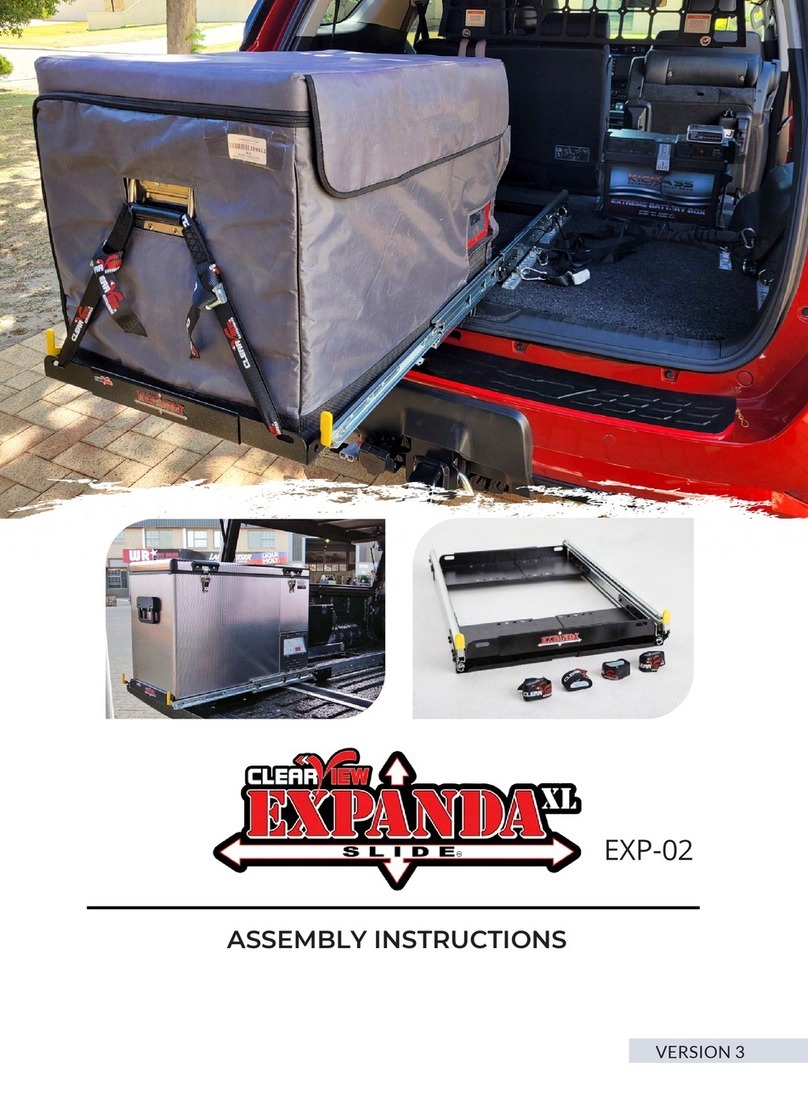
ClearView EXPANDA EXP-02 User manual

ClearView

ClearView EXPANDA EXP-02 User manual

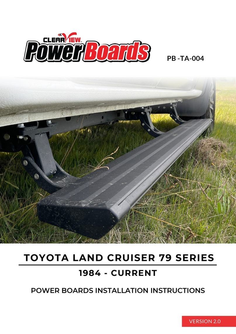
ClearView PowerBoards PB -TA-004 User manual

ClearView

ClearView PowerBoards PB -TA-004 User manual

ClearView CleanCam 1006 User manual

ClearView

ClearView CleanCam 1006 User manual

ClearView POWER SLIDE User manual

ClearView

ClearView POWER SLIDE User manual

ClearView CV-LR-D34-EB Guide

ClearView

ClearView CV-LR-D34-EB Guide

ClearView CV-JP-GC-IEB Instruction sheet

ClearView

ClearView CV-JP-GC-IEB Instruction sheet

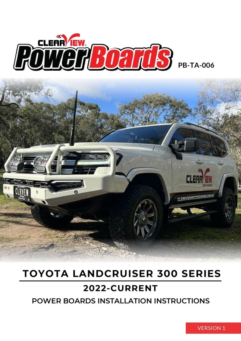
ClearView PowerBoards PB-TA-006 User manual

ClearView

ClearView PowerBoards PB-TA-006 User manual

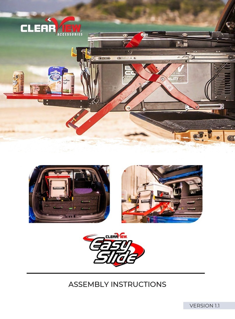
ClearView Easy Slide User manual

ClearView

ClearView Easy Slide User manual

ClearView PowerBoards PB-NN-003 User manual

ClearView

ClearView PowerBoards PB-NN-003 User manual

ClearView FRIDGE CAGE CAGE-01 User manual

ClearView

ClearView FRIDGE CAGE CAGE-01 User manual

ClearView Easy Slide Operation manual

ClearView

ClearView Easy Slide Operation manual

Popular Automobile Accessories manuals by other brands

Kompernass KH 4061 operating instructions

Kompernass

Kompernass KH 4061 operating instructions

Fieryred 93S-FS7S-UFA2 instructions

Fieryred

Fieryred 93S-FS7S-UFA2 instructions

APA 16506 operating instructions

APA

APA 16506 operating instructions

MTX THUNDERFORM installation instructions

MTX

MTX THUNDERFORM installation instructions

Power Hawk AUTO CRIB-IT AC-14 instruction manual

Power Hawk

Power Hawk AUTO CRIB-IT AC-14 instruction manual

RECARO 68.92.19 installation instructions

RECARO

RECARO 68.92.19 installation instructions

Safe Fleet PRIME DESIGN UVX 211 manual

Safe Fleet

Safe Fleet PRIME DESIGN UVX 211 manual

Saris SENTINEL Assembly instructions

Saris

Saris SENTINEL Assembly instructions

Whelen Engineering Company FastTrax FTF2 installation guide

Whelen Engineering Company

Whelen Engineering Company FastTrax FTF2 installation guide

Havis-Shields 2002-2008 Ford Explorer C-TCB-26 Install instructions

Havis-Shields

Havis-Shields 2002-2008 Ford Explorer C-TCB-26 Install instructions

Neuspeed 25.02.22.2 installation instructions

Neuspeed

Neuspeed 25.02.22.2 installation instructions

v.link VL3-SC15 manual

v.link

v.link VL3-SC15 manual

Metra Electronics 99-3301 installation instructions

Metra Electronics

Metra Electronics 99-3301 installation instructions

PUREGEAR AutoGrip user manual

PUREGEAR

PUREGEAR AutoGrip user manual

Toyota 55405-05160 installation instructions

Toyota

Toyota 55405-05160 installation instructions

Front Runner FAJL002 manual

Front Runner

Front Runner FAJL002 manual

Voxx Electronics PURSUIT install guide

Voxx Electronics

Voxx Electronics PURSUIT install guide

VBG Onspot Mounting instructions

VBG

VBG Onspot Mounting instructions

manuals.online logo
manuals.online logoBrands
  • About & Mission
  • Contact us
  • Privacy Policy
  • Terms and Conditions

Copyright 2025 Manuals.Online. All Rights Reserved.