Refrigerating Specialties Division 2
condition. This will prevent rapid repeat alarms due to
equipment failure.
• Channel 2 and 3 (Level Controls)
• The Level Control channels require a "Low" and a
"High" level setting.
• Push the "Channel" button on the keypad until the
Channel "2 or 3" and mode "L" (Low Level) is displayed.
Using the arrow keys, make your Low Level setting.
Press the "Enter" key, a "BEEP" will confirm your entry.
• Push the "Channel" button again. The "Mode" LED will
change from "L" to "H" (High Level). Again, using the
arrow keys, make your High Level setting, press the
"Enter" key and a "BEEP" will confirm your entry.
Programmable Relay Disposition
• Channels 1, 4 and 5 have programmable relay disposi-
tions. Channels 1 default to "H" (High Level), 4 and 5
default to "L" (Low Level).
• First select the channel by pressing the "Channel" but-
ton on the keypad. Pay special attention to the letter
displayed on the "Mode" LED.
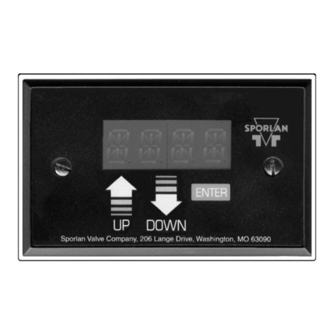
• Press the "Mode" key on the keypad. You will see the
displayed letter change from and "H" to an "L". Press-
ing the key again will return the "H" on the "Mode" LED.
• Select the Mode. If you started with an "H" displayed,
select the "L" to change the relay disposition.
• Use the "Up", "Down" keys to select the level for the
channel.
• Press the "Enter" key. You will hear a BEEP to verify
your entry. You will also notice the LED for the chan-
nel will light-up or turnoff depending on the disposition
selected.
Level Test Mode: 2 Modes Available
(With Relays De-energized & Energized)
First Mode: Display responds, relays maintain their dis-
positon. Second Mode: Both relays and display respond
to confrim control circuits.
First Mode
• First scroll through the channels by pressing the
"Channel" button on the keypad until a single "t" is
displayed in the "Channel" segment of the LED.
• Press the "Mode" key on the keypad. A second "t" will
appear in the "Mode" segment of the LED.
• Push the "Up", "Down" arrow key's on the keypad to
simulate a level change. The LED's on the right will
light-up or go off (depending on the relay disposition
selected) as the channel set-point is passed. The 4-20
mA output will also change while simulating a level
change.
Second Mode
• To test the level settings and relay function, follow the
same procedure for the De-energized Test Mode to the
point where "tt00" is displayed on the LED.
• Using the "Up" arrow key, scroll through the channel Fig. 2
ITP Probe Installed In Standpipe
ITP Probe
R/S Standpipe Cap
Globe Valve with
Horizontal Stem
Level Column
Sight Glasses
Globe Valve with
Horizontal Stem
Weld
Optional Oil Drain
settings one at a time. After each set-point is passed,
press and hold the "Enter" key for about 5 seconds. The
"tt" segments will flash and you will hear the relay en-
ergized or de-energized depending on the relay disposi-
tion.
• Note: Caution should be used during this procedure to
prevent Alarms and Equipment Shut Downs.
2445 S.25th Ave Broadview Ill 60155
T708-681-6300 F708-681-6306
