Page 18
823136EN
08/20/2012
Cleco®
Repair Instructions
9 Repair instructions
9.1 Excessive vibration
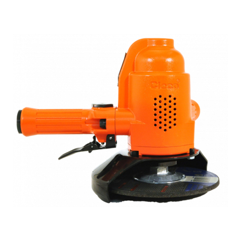
The primary source of vibration when using a portable grinder is an abrasive
wheel that is out of balance, out of round, untrue, or possibly a combination of
all three. The use of quality abrasive wheels that are well balanced, round and
true is highly recommended to signicantly reduce tool vibration.
Some abrasive wheels lose their balance, roundness, and trueness as they wear from use. Because of
the abusive nature of the vibration caused by out of balance, out of round, and untrue condition of some
abrasive wheels, it is felt that these wheels are more susceptible to failure.
Excessive vibration may signal eminent wheel failure. Flat spotting on the abrasive wheel, caused by
grinding the wheel to a stop after the power has been shut off, can result in changes to the balance and
shape of the wheel. Be sure the grinding wheel has stopped before setting the tool down. Set the tool
in a tool holder when not in use.
9.2 General disassembly
Disconnect the air supply from the tool and remove the wheel guard and grinding wheel.
9.3 Removing the motor unit from the motor housing
Insert a 5/16” hex wrench (clamped in a vise) into the spindle shaft and remove the driving ange.
Removing the housing bolts will allow the governor housing to be removed from the motor housing.
Remove the motor unit from the rear of the motor housing.
9.4 Motor unit disassembly
Remove the governor assembly (left hand threads) from the rear of the motor unit. Clamping on the
cylinder, hold the motor unit in a vise with the rear bearing plate facing up. Using a soft 1/4” rod and a
suitable hammer, drive the rotor shaft out of the overspeed shut-off disc and rear rotor bearing. This will
allow the various motor unit components to be removed from the rotor.
IMPORTANT NOTE: The overspeed shut-off disc is an assembly and must not be disassembled.
Do not remove the disc seal plate unless the rear bearing plated needs to be replaced.
9.5 Governor disassembly
Remove the governor pin retainer. Using a 3/32” punch, drive out the governor weight pins. After
removing the weights and two washers, the governor cone pin can be driven out using the 3/32” punch.
Note: Always use a new governor cone pin when the governor is reassembled. Removing the
governor adjusting nut will allow removal of the governor spring.
9.6 Throttle handle disassembly
To replace the throttle valve seal, remove the throttle valve cap to remove the throttle valve
components.
This tool is equipped with two air screens for protection of the motor components from foreign material.
The air screen located in the inlet bushing may be removed for cleaning and inspection by removing
the inlet bushing. If the screen is torn or damaged, the inlet bushing should be replaced. The air screen
located between the throttle handle and motor housing may be removed for cleaning and inspection by
unscrewing the two socket head cap screws. Replace this screen if there is apparent damage.


