ClimateMaster ACDU03 User manual

Operation Manual
97B0106N01
Rev.: 11/3/17
ACDU03 Communicating
Service Tool
Table of Contents
Caution:
These instructions are intended to be used by the installer or service personnel. End users are NOT advised to change or
modify any of these settings. Doing so may cause the equipment to stop working properly and/or may void the warranty on
both the thermostat and the equipment.
Section Title Page
1.0 Connection 3
2.0 Menu Structure 4
3.0 System Configuration 4
3.1 Airflow Selection 4
3.2 Option Selection 5
3.3 Unit Configuration 5
3.4 Pump Configuration 6
3.5 Valve Configuration 6
3.6 Multi-Unit Configuration 7
4.0 Service Mode 8
4.1 Manual Operation 8
4.2 Control Diagnostics 8
4.3 Dipswitch Configuration 9
4.4 Fault History 9
4.5 Clear Fault History 11
5.0 Revision History 12

This page was intentionally left blank.
3
ACDU03 Communicating Service Tool
Rev.: November 3, 2017
ClimateMaster’s Communicating Service Tool (ACDU03) allows install and service technicians to configure and diagnose
ClimateMaster Digital Communicating Units without installing a digital communicating thermostat.
Using the Service Tool, a technician can ELECTRONICALLY:
1. Configure items like: airflow, heat pump options and configuration, pump or modulating valve operation, unit family, unit
size, etc.
AND
2. Diagnose the unit by operating it manually, performing control diagnostics, viewing dip switch configurations, or by
viewing fault history and operating conditions when a fault occurred.
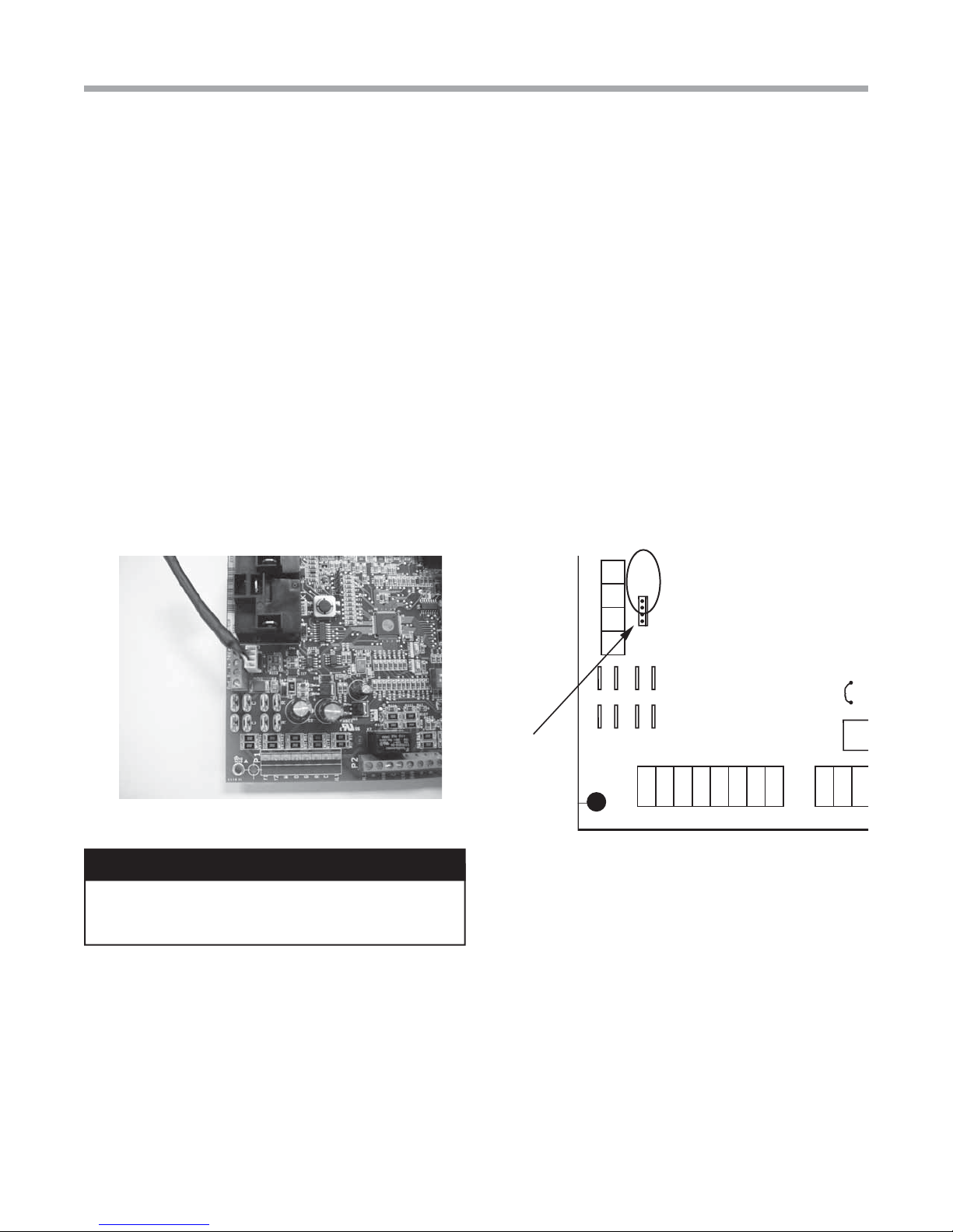
The Service Tool connects to the DXM2 board with a 4-Wire Connector as shown below:
P1
Alarm
O
Y1
Y2
W
G
C
R
AL1
R
C
R
NSB
AL2
JW1
P2
P5
B-
Gnd
A+ 24V
Service tool
connection
DXM2
Board
DXM2
DXM2
Board
Board
1.0 Connection
WARNING!
WARNING!
Connecting wire harness while unit is
powered on or connecting backward may damage
service tool.
Note: For Vertical Stack models (TSM, TSL) must
order harness for connection to service port outside
chassis. Harness part number 11B0100N27. DXM2 to
service port is factory wired.

ACDU03 Communicating Service Tool
Rev.: November 3, 2017
4Geothermal Heat Pump Systems
2.0 Menu Structure
System Configuration
Airflow Selection
Option Selection
Unit Configuration
Pump Configuration
Valve Configuration
Service Mode
Manual Operation
Control Diagnostics
Dipswitch Configuration
Fault History
Clear Fault History
Menu Structure
Start-up Screen
System Configuration Menu
SERVICE TOOL MENU
SYSTEM CONFIG
SERVICE MODE
ACDU03 1.00
SELECT OPTION
3.0 System Configuration
Use the System Configuration option on the start-up screen
to adjust critical equipment settings.
The System Configuration information will be automatically
obtained from each communicating control in the system.
Note 1: The Airflow Selection menu (section 3.1) will not be
present if the connected communicating control system has
no blower.
Note 2: The Pump Configuration menu (section 3.4) will
not be present if the connected communicating control is
configured for No Loop Configuration (OTHER).
Note 3: The Valve Configuration menu (section 3.5) will
not be present if the connected communicating control is
configured for No Loop Configuration (OTHER).
3.1 AIRFLOW SELECTION
Adjust the airflow settings for each system operating mode
using the up/down arrow buttons. Press the center button to
select each item.
• Airflow Settings (defaults stored in control) -
valid range: obtained from control (in 25 CFM
increments)
• Blower Off Delay (default 60 seconds) – valid
range: 0 to 255 seconds (in 5 second increments)
NOTE 1: The Airflow Settings will only be present if the
connected communicating control is configured for ECM
blower.
NOTE 2: If multiple units are connected to one thermostat,
refer to section 3.6 for unit selection.
SYSTEM CONFIGURATION
AIRFLOW SELECTION
OPTION SELECTION
UNIT CONFIG TES026
PUMP CONFIGURATION
SELECT OPTION
PREVIOUS SELECT

5
ACDU03 Communicating Service Tool
Rev.: November 3, 2017
Option Selection Menu
Unit Configuration Menu
OPTION SELECTION
MOTORIZED VALVE OFF
COMPRESSOR ASCD 0
SELECT OPTION
PREVIOUS SELECT
NOTE: “Motorized Valve” used here refers to a two-position
motorized water valve, not to be confused with the modulating
motorized water valve found in the LOOP CONFIG.
3.2 OPTION SELECTION
This option allows the configuration of heat pump options to
be modified.
Adjust the Option settings using the up/down arrow buttons.
Press the center button to select each item.
• Motorized Valve (defaults stored in control) – valid
range: Off, On “On” delays compressor start until
the valve is fully open.
• Compressor ASCD (Anti-Short Cycle Delay (default
stored in control) – valid range: 5 to 8 (in 1 minute
increments)
NOTE 1: The CompressorAnti-Short Cycle Delay setting
provides equipment protection by forcing the compressor to
wait a few minutes before restarting.
NOTE 2: If multiple units are connected to one thermostat,
refer to section 3.6 for unit selection.
3.3 UNIT CONFIGURATION
Adjust the Unit Configuration settings including Heat
Pump Family, Heat Pump Size, Blower Type, and Loop
Configuration using the up/down arrow buttons. Press the
center button to select each item.
• Heat Pump Family (default stored in control) –
valid range: TE, TY, TES, TEP, TRT, TSM, TSL
• Heat Pump Size (default stored in control) – valid
range: depends on Heat Pump Family setting
• Blower Type (default stored in control) – valid
range: NO BLOWER, 2-SPD PSC, COM ECM-V,
1-SPD PSC, 2-SPD CTM, PWM ECM, VFD
• Loop Config (default stored in control) – valid
range: Other, VS PUMP, MOD VALVE
Airflow, pump and valves can be configured from ‘System
Configuration’ screen.
Select ‘VS PUMP PARALLEL’ when applying an internal
variable speed flow controller with other flow controllers on a
single loop in parallel.
NOTE: Refer to section 3.6.3 for multi-unit configuration
instructions.
UNIT CONFIGURATION
CURRENT CONFIG TE026
HEAT PUMP FAMILY TE
HEAT PUMP SIZE 026
BLOWER TYPE ECM
LOOP CONFIG VS PUMP
SELECT OPTION
PREVIOUS SAVE

ACDU03 Communicating Service Tool
Rev.: November 3, 2017
6Geothermal Heat Pump Systems
VARIABLE SPD INTERNAL
PUMP CONFIGURATION
LOOP OPTION SINGLE
PUMP CONTROL FIXED
HEATING STAGE 1 60%
COOLING STAGE 2 75%
COOLING STAGE 1 50%
COOLING STAGE 2 70%
PREVIOUS SELECT
3.4 PUMP CONFIGURATION
vFlow™ vs internal flow control pump can be controlled either
through temperature differential (Delta T) or can be set to
specific speed (fixed; % of full speed for each heat and cool
stage).
Can be configured for either single pumping or parallel
pumping.
Configure temperature differentials at the thermostat for
vFlow™ units with an internal flow control pump.
Adjust the Pump Configuration settings using the up/down
arrow buttons. Press the center button to select each item.
• Heating Delta T (default stored in control) –
valid range: 4 to 12ºF (in 1ºF increments)
• Cooling Delta T (default stored in control) –
valid range: 9 to 20ºF (in 1ºF increments)
Maximum Heat LWT (valid range based on specific model;
refer to model IOM). Minimum Cool LWT (valid range based
on specific model; refer to model IOM).
NOTE: Refer to section 3.6.3 for multi-unit configuration
instructions.
To control vs pump by fixed speed, select ‘Pump Control’,
press , use down arrow to select ‘Fixed’, and press to
save.
Default stored in control. Valid range: 15% - 90% (in 1%
increments)
Heating Stage 1 Cooling Stage 1
Heating Stage 2 Cooling Stage 2
If Pump Configuration is set to ‘VS PUMP PARALLEL’, valid
range changes to 50-90% (in 1% increments).
3.5 VALVE CONFIGURATION
Configure temperature differentials at the thermostat for
vFlow™ units with a motorized modulating valve.
Adjust the Valve Configuration settings using the up/down
arrow buttons. Press the center button to select each item.
• Heating Delta T (default stored in control) –
valid range: 4 to 12ºF (in 1ºF increments)
• Cooling Delta T (default stored in control) –
valid range: 9 to 20ºF (in 1ºF increments)
NOTE 1: Minimum and Maximum degree values are shown
only when the control is configured with the appropriate
values.
NOTE 2: Refer to section 3.6.3 for multi-unit configuration
instructions.
3.5.1 MODULATING VALVE OFF POSITION
For certain commercial multi-unit applications, the modulating
valve can be kept slightly open by choosing values 3.3-4.0.
MODULATING VALVE
CONFIGURATION
OFF POSITION 0.0
VALVE CONTROL DELTA T
HEATING DELTA T 7 F
COOLING DELTA T 10 F
MAXIMUM HEAT LWT 80 F
MINIMUM COOL LWT 40 F
PREVIOUS SELECT
VARIABLE SPD INTERNAL
PUMP CONFIGURATION
LOOP OPTION PARALLEL
PUMP CONTROL DELTA T
HEATING DELTA T 7 F
COOLING DELTA T 10 F
MAXIMUM HEAT LWT 80 F
MINIMUM COOL LWT 40 F
PREVIOUS SELECT

7
ACDU03 Communicating Service Tool
Rev.: November 3, 2017
Two
connections
on DXM2
board to allow
for multi-unit
installation
Or
AIRFLOW SELECTION
TT026 S N - - - - - 1 2 3 4
TT026 S N - - - - - 5 6 7 8
TT038 S N - - - - - 9 0 1 2
PREVIOUS SELECT
OPTION SELECTION
TT026 S N - - - - - 1 2 3 4
TT026 S N - - - - - 5 6 7 8
TT038 S N - - - - - 9 0 1 2
PREVIOUS SELECT
3.6 MULTI-UNIT CONFIGURATION
If multiple units are connected to one ATC thermostat upon
unit start-up, the thermostat will automatically register the
serial numbers of all units connected to it.
NOTE: Multiple units may be connected directly to the ATC
thermostat or connected to one another in series, as shown
by the figure below.
3.6.1 MULTI-UNIT AIRFLOW SELECTION
In section 3.1, when an installer selects “Airflow Selection”
from the System Configuration menu, the installer may
choose the unit to configure by the last 4 digits of its serial
number from the following screen.
3.6.2 MULTI-UNIT OPTION SELECTION
In section 3.2, when an installer selects “Option Selection”
from the System Configuration menu, the installer may
choose the unit to configure by the last 4 digits of its serial
number from the following screen.
3.6.3 Multi-Unit, Unit, Pump, & Valve Configuration
To configure Unit, Pump, and Valve options in sections 3.3-
3.5, the thermostat must be connected to only one unit at a
time.

ACDU03 Communicating Service Tool
Rev.: November 3, 2017
8Geothermal Heat Pump Systems
4.0 Service Mode
4.1 MANUAL OPERATION
Manual Operation mode allows service personnel to manually
command operation for any of the thermostat outputs, blower
speed, as well as pump speed or valve position to help
troubleshoot specific components.
NOTE 1: The ECM Airflow adjustment will not be present if the
connected communicating control (DXM2) is not configured for
ECM (section 3.1).
NOTE 2: The Pump Speed adjustment will not be present
if the connected communicating control (DXM2) is not
configured for Pump (section 3.4).
NOTE 3: The Valve Position adjustment will not be present if
the connected communicating control (DXM2) is configured for
Valve (section 3.5).
4.2 CONTROL DIAGNOSTICS
Control Diagnostics mode allows service personnel to view
the status of all physical inputs, switches and temperature
sensor readings, as well as the operational status of the heat
pump at the thermostat.
Navigate between diagnostic screens using the left/right
arrow buttons.
NOTE: The Pump Status will not be present if the connected
communicating control (DXM2) is not configured for Pump
(section 3.4).
SERVICE MODE
MANUAL OPERATION
CONTROL DIAGNOSTICS
DIPSWITCH CONFIG
FAULT HISTORY
CLEAR FAULT HISTORY
SELECT OPTION
PREVIOUS SELECT
MANUAL OPERATING MODE
Y1 COMM OUTPUT OFF
Y2 COMM OUTPUT OFF
W COMM OUTPUT OFF
O COMM OUTPUT OFF
G COMM OUTPUT OFF
H COMM OUTPUT OFF
DH COMM OUTPUT OFF
ECM AIRFLOW 0
PUMP SPEED 0%
TEST MODE OFF
SELECT OPTION
PREVIOUS SELECT
CONTROL STATUS
TEMPERATURES
LT1 TEMP 38.1
LT2 TEMP 79.9
COMP DISCHARGE 157.7
HOT WATER EWT 121.5
LEAVING AIR 75.1
LEAVING WATER 73.3
ENTERING WATER 78.5
CONTROL VOLTAGE 26.4
ECM BLOWER RPM 550
ECM TARGET CFM 800
ECM BLWR STATIC N/A
PREVIOUS NEXT
CONTROL DIAGNOSTICS
HP SWITCH CL
LOC SWITCH CL
Y1 PHYSICAL INPUT ON
Y2 PHYSICAL INPUT OFF
W PHYSICAL INPUT OFF
O PHYSICAL INPUT ON
G PHYSICAL INPUT ON
H PHYSICAL INPUT OFF
EMERG SHUTDOWN OFF
NIGHT SETBACK OFF
OVR INPUT OFF
PREVIOUS NEXT
CONTROL DIAGNOSTICS
PUMP OPERATION
PUMP SPEED 60%
PUMP WATTS 140
FLOW RATE GPM 7.4
PREVIOUS

9
ACDU03 Communicating Service Tool
Rev.: November 3, 2017
4.3 DIPSWITCH CONFIGURATION
Dipswitch Configuration mode allows the service personnel
to view the status of all dipswitch settings for the connected
communicating control (DXM2/AXM) at the thermostat.
Navigate between configuration screens using the left/right
arrow buttons.
NOTE: The unit control dipswitch settings cannot be changed
from the thermostat or configuration/diagnostics tool.
S1 Dipswitch Status
S2 Dipswitch Status
S3 Dipswitch Status
Fault History
CONTROL CONFIGURATION
DIPSWITCH S1
1 ON UPS ENABLED
2 ON DUAL COMP STG 1
3 ON HEAT PUMP TSTAT
4 ON RV O THERMOSTAT
5 ON DEHUMID OFF
6 ON EH2 AUX HEAT
7 ON BOILERLESS
8 ON SEE DXM2 AOM
PREVIOUS NEXT
CONTROL CONFIGURATION
DIPSWITCH S2
1 ON \ ACCESSORY 1
2 ON ACCESSORY 2
3 ON/
4 ON \ ACCESSORY 2
5 ON ACTIVE W/ COMP
6 ON /
7 ON H DEHUM INPUT
8 ON FACTORY SETTING
PREVIOUS NEXT
CONTROL CONFIGURATION
DIPSWITCH S3
1 ON FACTORY SETTING
2 OFF HWG TEST OFF
3 OFF HWG SP 125
4 OFF HWG DISABLED
JW3 LT1 SETTING WELL
PREVIOUS
TT038 SN - - - - - 0 1 2 3
LAST 5 FAULTS
LT1 LOW WATER TEMP
NO FAULT
NO FAULT
NO FAULT
NO FAULT
NEXT
PREVIOUS SELECT
4.4 FAULT HISTORY
Fault History mode displays the five most recent stored fault
codes for the connected communicating control (DXM2).
Navigate between control fault codes using the up/down
arrow buttons. Press the center button to view more
information about the highlighted fault code.

ACDU03 Communicating Service Tool
Rev.: November 3, 2017
10 Geothermal Heat Pump Systems
4.4.1 Temperature Conditions
Displays detailed temperature readings that were
recorded at the time the fault occurred
4.4.0 Fault Conditions Menu
4.4.2 Flow Conditions
Displays detailed blower and pump speed / valve posi-
tion readings that were recorded at the time the fault
occurred.
4.4.3 Input/Output Conditions
Displays the status of all physical and communicated
inputs, switches, and control outputs that were re-
corded at the time the fault occurred.
FAULT CONDITION MENU
LT1 LOW WATER TEMP
HEAT 1 11:11 AM 11/14
FAULT TEMP CONDITIONS
FAULT FLOW CONDITIONS
FAULT I/O CONDITIONS
FAULT CONFIG COND
FAULT POSSIBLE CAUSES
PREVIOUS SELECT
FAULT TEMPERATURE CONDITIONS
LT1 LOW WATER TEMP
HEAT 1 11:11 AM 11/14
LT1 TEMP 28.1
LT2 TEMP 97.3
HOT WATER EWT 121.5
COMP DISCHARGE 157.7
LEAVING AIR 92.7
LEAVING WATER 34.9
ENTERING WATER 42.1
CONTROL VOLTAGE 26.4
PREVIOUS
FAULT I / O CONDITIONS
LT1 LOW WATER TEMP
HEAT 1 11:11 AM 11/14
TSTAT SAFETY OUTPT
CONV COMM HPS
Y1 Y1 LOC CC
Y2 Y2 CO RV
WW ACC1
OOOUTPT ACC2
GGFAN AL1
HH HWG EH1
OVR DH PUMP EH2
PREVIOUS
FAULT FLOW CONDITIONS
LT1 LOW WATER TEMP
HEAT 1 11:11 AM 11/14
ECM TARGET CFM 800
ECM BLOWER RPM 550
FLOW RATE GPM 6.5
PUMP SPEED 60%
PUMP WATTS 140
LOOP CONFIG VS PUMP
PREVIOUS SINGLE
FAULT FLOW CONDITIONS
LT1 LOW WATER TEMP
HEAT 1 11:11 AM 11/14
ECM TARGET CFM 800
ECM BLOWER RPM 550
VALVE POSITION 10.0V
LOOP CONFIG MOD VALVE
PREVIOUS MIN POS

11
ACDU03 Communicating Service Tool
Rev.: November 3, 2017
4.4.3 Configuration Conditions
Displays the status of all dipswitch settings that were
recorded at the time the fault occurred.
4.4.4 Possible Causes
Displays possible causes as to why the fault occurred
4.5 CLEAR FAULT HISTORY
Clear Fault History will clear all fault codes stored in the
thermostat as well as the fault history in any connected
communicating controls (DXM2/AXM).
FAULT CONFG CONDITIONS
LT1 LOW WATER TEMP
HEAT 1 11:11 AM 11/14
S1 S2 S3
1 ON 1 ON 1 ON
2 ON 2 ON 2 OFF
3 ON 3 ON 3 OFF
4 ON 4 ON 4 OFF
5 ON 5 ON
6 ON 6 ON LT1 WELL
7 ON 7 ON LT2 WELL
8 ON 8 ON
PREVIOUS
POSSIBLE FAULT CAUSES
LOW WATER COIL TEMP
LOW WATER TEMP - HTG
LOW WATER FLOW - HTG
LOW REFRIG CHARGE - HTG
INCORRECT LT1 SETTING
BAD LT1 THERMISTOR
PREVIOUS

ACDU03 Communicating Service Tool
Rev.: November 3, 2017
12 Geothermal Heat Pump Systems
5.0 Revision History
97B0106N01
ClimateMaster works continually to improve its products. As a result, the design and specifications of each product at the time for order may be
changed without notice and may not be as described herein. Please contact ClimateMaster’s Customer Service Department at 1-405-745-6000
for specific information on the current design and specifications. Statements and other information contained herein are not express warran-
ties and do not form the basis of any bargain between the parties, but are merely ClimateMaster’s opinion or commendation of its products.
© ClimateMaster, Inc. 2012
*97B0106N01*
7300 S.W. 44th Street
Oklahoma City, OK 73179
Phone: 405-745-6000
Fax: 405-745-6058
climatemaster.com
Rev.: January 23, 2019
Date Page # Description
23 Jan. 19 3,4 Update harness and service tool part number
3 Nov., 17 All Updated tstat Part number to ATC32U03
16 October, 2017 5 Update blower types
25 Jan., 2016 12 Updated Certification Logos
17 Apr., 14 3,5 Text Updated
11 Feb., 14 All ACDU01 Updated to ACDU02
23 Oct. 12 4-7 Unit Config, Pump Config and Valve Config Sections Updated
8 May, 12 All First Published
Table of contents
Other ClimateMaster Diagnostic Equipment manuals


