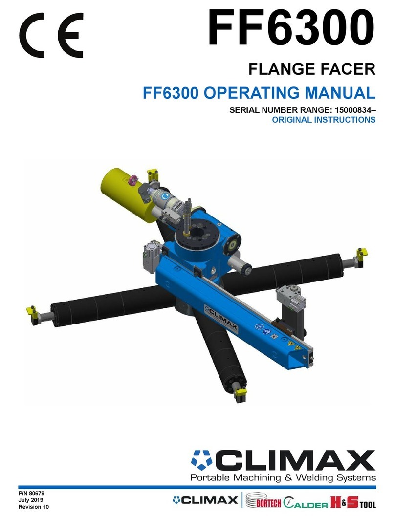
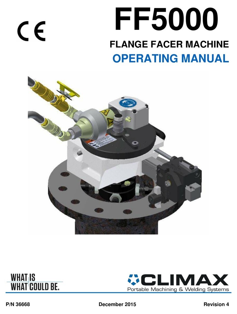
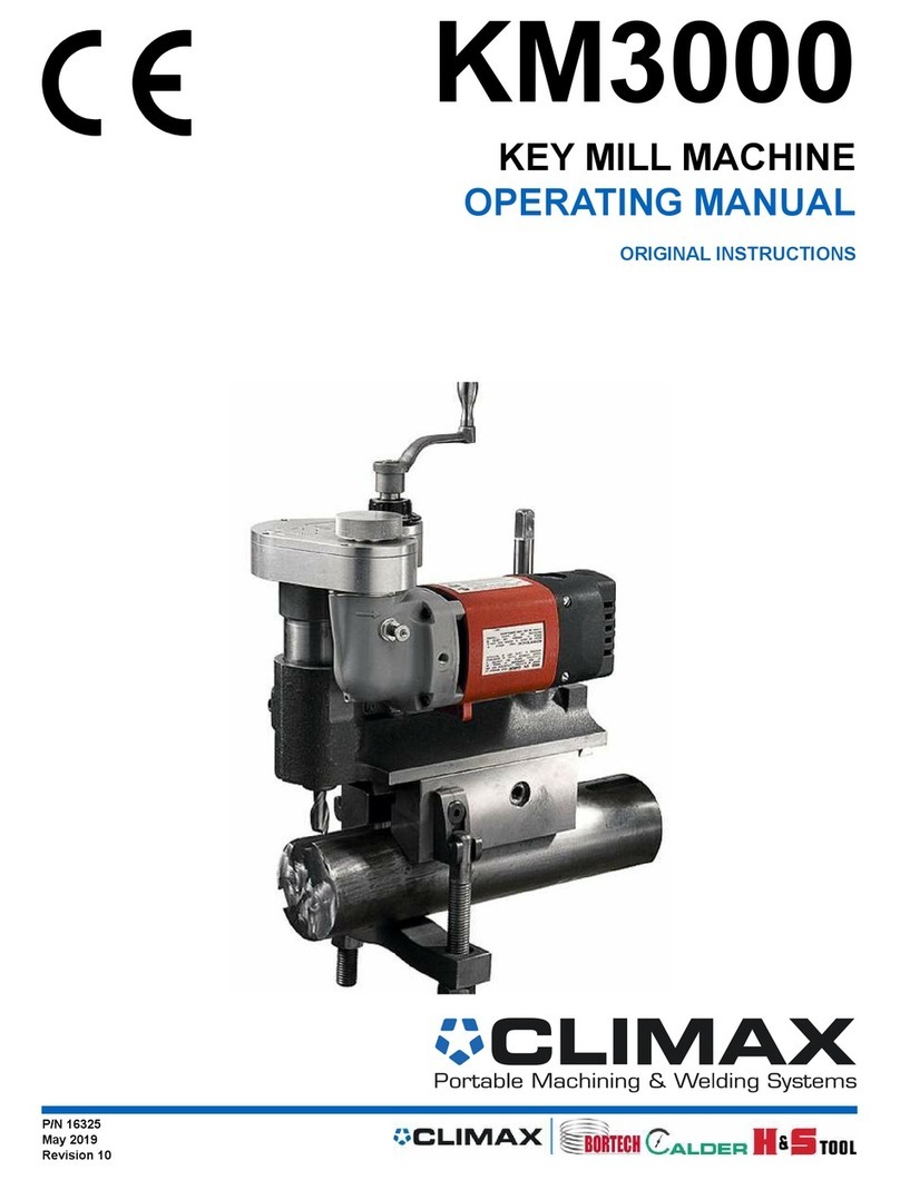
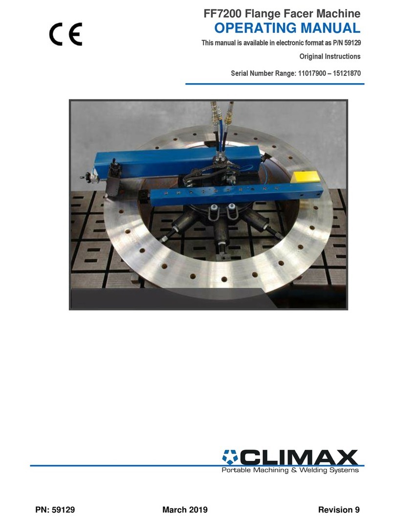
Climax BB6100 User manual

PN: 57017 May 2019 Revision 3
BB6100
BORING BAR
OPERATING MANUAL
ORIGINAL INSTRUCTIONS


P/N: 57017, Rev. 3 Page A
©2019 CLIMAX or its subsidiaries.
All rights reserved.
Except as expressly provided herein, no part of this manual may be reproduced, copied, transmitted,
disseminated, downloaded, or stored in any storage medium, without the express prior written consent
of CLIMAX. CLIMAX hereby grants permission to download a single copy of this manual and of
any revision hereto onto an electronic storage medium to be viewed and to print one copy of this
manual or any revision hereto, pro- vided that such electronic or printed copy of this manual or
revision must contain the complete text of this copyright notice and provided further that any
unauthorized commercial distribution of this manual or any revision hereto is prohibited.
At CLIMAX, we value your opinion.
For comments or questions about this manual or other CLIMAX documentation, please e-mail
For comments or questions about CLIMAX products or services, please call CLIMAX or e-mail
[email protected]. For quick and accurate service, please provide your representative with the following:
•Your name
•Shipping address
•Telephone number
•Machine model
•Serial number (if applicable)
•Date of purchase
CLIMAX World Headquarters
2712 East 2nd Street Newberg, Oregon 97132
USA
Telephone (worldwide): +1-503-538-2815
Toll-free (North America): 1-800-333-8311
Fax: 503-538-7600
H&S Tool World Headquarters
715 Weber Dr.
Wadsworth, OH 44281 USA
Telephone: +1-330-336-4550
Fax: 1-330-336-9159
hstool.com
CLIMAX | H&S Tool (UK Headquarters)
Unit 7 Castlehill Industrial Estate Bredbury
Industrial Park Horsfield Way
Stockport SK6 2SU, UK Telephone: +44 (0) 161-
406-1720
CLIMAX | H&S Tool (European Headquarters)
Am Langen
Graben 8 52353
Düren, Germany
Telephone: +49 24-219-1770
E-mail: [email protected]
CLIMAX | H&S Tool (Asia Pacific Head-
quarters)
316 Tanglin Road #02-01
Singapore 247978
Telephone: +65 9647-2289
Fax: +65 6801-0699
CLIMAX | H&S Tool (Middle East Headquarters)
Warehouse #5, Plot:
369 272 Um Sequim
Road
Al Quoz 4
PO Box 414 084
Dubai, UAE
Telephone: +971 04-321-0328

Page B BB6100 Operating Manual
CLIMAX WORLDWIDE LOCATIONS

P/N: 57017, Rev. 3 Page i
TABLE OF CONTENTS
1INTRODUCTION ....................................................................................................................1
1.1 Limited Warranty.......................................................................................................................................1
1.2 Alerts .........................................................................................................................................................2
1.3 Safety Precautions .....................................................................................................................................2
1.4 Machine Specific Safety Practices............................................................................................................. 3
1.5 Risk Assessment and Hazard Mitigation...................................................................................................5
1.6 Risk Assessment Checklist........................................................................................................................6
2OVERVIEW ............................................................................................................................7
2.1 About this manual......................................................................................................................................8
2.1.1 Recommended tools ..............................................................................................................................8
2.2 Receipt and inspection...............................................................................................................................8
2.3 Specifications and Dimensions.................................................................................................................. 9
2.4 Axial Feed Assembly................................................................................................................................. 14
3SETUP..................................................................................................................................15
3.1 Clamp collars.............................................................................................................................................15
3.2 About Boring Machine Support................................................................................................................. 15
3.3 Installing End-mount Bearing Support......................................................................................................16
3.3.1 To install the end-mount bearing support............................................................................................16
3.3.2 Clamping the bearing assembly to the bar...........................................................................................19
3.4 ID-mount bearing support..........................................................................................................................19
3.4.1 If mounting an end-mount bearing ......................................................................................................23
3.4.2 Clamping the bearing assembly to the bar...........................................................................................23
3.5 Preload bearing kit..................................................................................................................................... 23
3.6 RDU Setup................................................................................................................................................. 24
3.7 Mounting the Mechanical Axial Feed Unit ...............................................................................................26
3.7.1 Setting feed direction and rate.............................................................................................................27
3.7.2 Neutral (no feed)..................................................................................................................................27
3.7.3 Feed away from the axial feed unit......................................................................................................27
3.7.4 Feed toward the axial feed unit............................................................................................................28
3.7.5 Disengaging the feed under load .........................................................................................................28
3.7.6 Setting the feed rate.............................................................................................................................28
3.7.7 Stopping the feed.................................................................................................................................29
3.8 Mounting the Electric Axial Feed Assembly.............................................................................................29
3.8.1 Setting the Axial Feed Rate.................................................................................................................31
3.9 Tool Head Setup ........................................................................................................................................ 31
3.9.1 Small bore tool carrier setup................................................................................................................31
3.9.2 Small bore tool carrier boring head setup............................................................................................32
3.10 Micro-adjust boring head...........................................................................................................................33
3.11 Boring head setup ......................................................................................................................................36
3.11.1 To lock the tool carrier on the bar for other operations.......................................................................38
3.11.2 Do the following to remove the brass nut:...........................................................................................38
3.12 Install the slide arm onto the tool carrier ................................................................................................... 39
3.13 Adjusting the tool carrier for perpendicularity ..........................................................................................40
3.14 Feedbox assembly......................................................................................................................................40
3.15 Feedbox and trip arm set-up ......................................................................................................................40
3.16 Mechanical facing head setup....................................................................................................................40


Page ii BB6100 Operating Manual
3.17 Hydraulic power preparation and connection............................................................................................ 43
4OPERATION ........................................................................................................................45
4.1 Using the remote pendants ........................................................................................................................ 45
4.1.1 Feed pendant ....................................................................................................................................... 45
4.2 HPU pendant ............................................................................................................................................. 46
4.3 Manual override (electrical feed only)...................................................................................................... 46
4.4 Pre-startup checks...................................................................................................................................... 47
4.4.1 Running the machine........................................................................................................................... 47
4.4.2 Stopping the machine.......................................................................................................................... 47
4.4.3 Repetitive machining........................................................................................................................... 47
4.5 Disassembly............................................................................................................................................... 48
4.5.1 Standard disassembly.......................................................................................................................... 48
4.5.2 Optional disassembly .......................................................................................................................... 48
5MAINTENANCE ...................................................................................................................49
5.1 Recommended lubricants .......................................................................................................................... 49
5.2 Boring bar/lead screw assembly................................................................................................................ 49
5.3 Axial feed unit........................................................................................................................................... 49
5.4 Rotational drive unit.................................................................................................................................. 49
5.5 Bearing support assembly.......................................................................................................................... 49
5.6 Tool head assembly................................................................................................................................... 49
5.6.1 Boring head assembly ......................................................................................................................... 49
5.6.2 Mechanical facing head assembly....................................................................................................... 50
5.6.3 Tool carrier maintenance..................................................................................................................... 50
5.7 Hydraulic power unit and motor................................................................................................................ 50
6STORAGE............................................................................................................................51
6.1 Tool kit...................................................................................................................................................... 51
6.2 Spare Parts................................................................................................................................................. 53
7EXPLODED VIEWS AND PARTS LISTS.............................................................................55
8SCHEMATICS......................................................................................................................91
9SDS ......................................................................................................................................95

P/N: 57017, Rev. 3 Page 1
1 INTRODUCTION
1.1 Limited Warranty
Climax Portable Machine Tools, Inc. (hereafter referred to as “CLIMAX”) warrants
that all new machines are free from defects in materials and workmanship. This
warranty is available to the original purchaser for a period of one year after delivery.
If the original purchaser finds any defect in materials or workmanship within the
warranty period, the original purchaser should contact its factory representative and
return the entire machine, shipping prepaid, to the factory. CLIMAX will, at its
option, either repair or replace the defective machine at no charge and will return the
machine with shipping prepaid.
CLIMAX warrants that all parts are free from defects in materials and workmanship,
and that all labor has been performed properly. This warranty is available to the
customer purchasing parts or labor for a period of 90 days after delivery of the part or
repaired machine or 180 days on used machines and components. If the customer
purchasing parts or labor finds any defect in materials or workmanship within the
warranty period, the purchaser should contact its factory representative and return the
part or repaired machine, shipping prepaid, to the factory. CLIMAX will, at its
option, either repair or replace the defective part and/ or correct any defect in the
labor performed, both at no charge, and return the part or repaired machine shipping
prepaid.
These warranties do not apply to the following:
Damage after the date of shipment not caused by defects in materials or
workmanship
Damage caused by improper or inadequate machine maintenance
Damage caused by unauthorized machine modification or repair
Damage caused by machine abuse
Damage caused by using the machine beyond its rated capacity
All other warranties, express or implied, including without limitation the warranties
of merchantability and fitness for a particular purpose are disclaimed and excluded.
Terms of Sale
Be sure to review the terms of sale which appear on the reverse side of your invoice.
These terms control and limit your rights with respect to the goods purchased from
CLIMAX.
About This Manual
CLIMAX provides the contents of this manual in good faith as a guideline to the
operator. CLIMAX cannot guarantee that the information contained in this manual is
correct for applications other than the application described in this manual. Product
specifications are subject to change without notice.

Page 2 BB6100 Operating Manual
1.2 Alerts
Pay careful attention to the alerts appearing in this manual. Alert types are defined in
the following examples.
DANGER
concerns a condition, procedure, or practice that, if not avoided or
strictly observed, WILL result in injury or loss of life.
WARNING
concerns a condition, procedure, or practice that, if not avoided or
strictly observed, COULD result in injury or loss of life.
CAUTION
concerns a condition, procedure, or practice that, if not avoided or
strictly observed, could result in minor or moderate injury.
NOTICE
concerns a condition, procedure, or practice worthy of special
attention.
TIP:
A tip provides additional information that can aid in completion of a
task.
1.3 Safety Precautions
CLIMAX leads the way in promoting the safe use of portable machine tools. Safety
is a joint effort. You, the machine operator, must do your part by being aware of your
work environment and closely following the operating procedures and safety
precautions contained in this manual, as well as your employer’s safety guidelines.
Observe the following safety precautions when operating or working around the
machine.
Training –Before operating this or any machine tool, you should receive instruction
from a qualified trainer. Contact CLIMAX for machine-specific training information.
Risk Assessment –Working with and around this machine poses risks to your
safety. You, the end user, are responsible for conducting a risk assessment of each
job site before setting up and operating this machine.

P/N: 57017, Rev. 3 Page 3
Intended Use –Use this machine in accordance with the instructions and
precautions in this manual. Do not use this machine for any purpose other than its
intended use as described in this manual.
Personal Protective Equipment –Always wear the appropriate personal
protective gear when operating this or any other machine tool. Eye and ear protection
are required when operating or working around the machine. Flame-resistant clothing
with long sleeves and legs is recommended when operating the machine, as hot
flying chips from the workpiece may burn or cut bare skin.
Work Area –Keep the work area around the machine clear of clutter. Keep all cords
and hoses away from the work area when operating the machine.
Lifting –Many CLIMAX machine components are very heavy. Whenever possible,
lift the machine or its components using proper hoisting equipment and rigging.
Always use designated lifting points on the machine. Follow all lifting instructions in
the setup procedures of this manual.
Lock Out/Tag Out –Lock out and tag out the machine before doing maintenance.
Moving Parts –CLIMAX machines have numerous exposed moving parts and
interfaces that can cause severe impact, pinching, cutting, and other injuries. Except
for operating controls, avoid contact with moving parts by hands or tools during
machine operation. Secure hair, clothing, jewelry, and pocket items to prevent them
from becoming entangled in moving parts.
Sharp Edges –Cutting tools and workpieces have sharp edges that can easily cut
skin. Wear protective gloves and exercise caution when handling a cutting tool or
workpiece.
Hot Surfaces –During operation, motors, some housings, and cutting tools can
generate enough heat to cause severe burns. Pay attention to hot surface labels, and
avoid contact with bare skin until the machine has cooled.
1.4 Machine Specific Safety Practices
This list includes safety practices applicable to CLIMAX Portable Machines.
All aspects of the machine have been designed with safety in mind. Warning signs
are affixed to the machine to warn of residual hazards associated with machine
relating to operation, setup, whether or not it is in use.
Machine safety features—Never attempt to defeat or override the safety features
designed into the machine.
Securing the machine—Never attempt to run the machine without first securing
it to a stable work piece.
Personal Protection—Wear safety glasses, earplugs, and safety shoes while
operating the machine. Gloves are not a form of protection and should not be worn
while operating the machine. Metal chips and debris created by the machine should
be disposed using a dust pan and broom.

Page 4 BB6100 Operating Manual
Keeping clean—Maintain your machine according to the procedures described in
this manual to maximize safety and machine longevity.
Keep clear—Keep clear of the machine during operation. Never lean or reach into
the machine to remove chips or to adjust the machine while it is running. Doing so
can cause serious injury or death.
Controls—Operator controls are located outside the danger zone of the machine.
All controls perform a one-to-one action. The machine is not supplied with a power
unit and, therefore, does not have an E-stop.
Machine setup and disassembly—With a modular design, the machine can be
broken down into components to ease setup.
Machine guards—There are no guards used on this machine.
Clamp Collars—To prevent the bar from sliding through the support bearings, or
falling, use P/N 25010 –The collars are used to secure the bar when the machine is
in the vertical orientation. Torque these collars to 25 ft-lbs (34 Nm). Clamp collars
should be positioned ABOVE at least 2 support bearings when installed in a vertical
orientation. Clamp collars should be shouldered against the bearing when in use.
Electrical emissions—There are no electrical components used on this machine.
Operator station—Due to the nature of portable machinery, no designated
operator’s station exists.
Moving parts—The operator is not exposed to the cutter head when the work piece
is being machined. Keep all cords and hoses away from moving parts during
operation. If the cords become tangled in the machinery the operator could be
seriously injured and the machine extensively damaged.
Fluids—Cutting fluids are required for machine operation. The machine itself does
not emit any fluids.
Lifting—When lifting the machine for setup or disassembly, a conventional sling-
type lift is suggested for convenience and safety of the operator. Use designated
lifting eyes. Do not lift the machine by the turning bar.
Repetitive motion—Individuals can be susceptible to disorders of the hands and
arms when exposed to tasks that involve highly repetitive motions and/or vibration.
To reduce the likelihood of these disorders, follow these guidelines:
Use minimum hand grip force
Keep wrists straight
Avoid exposure to continue vibration
Avoid repeated bending of wrists and hands
Keep hands and arms warm and dry

P/N: 57017, Rev. 3 Page 5
1.5 Risk Assessment and Hazard Mitigation
Machine Tools are specifically designed to perform precise material-removal
operations.
Stationary Machine Tools include lathes and milling machines and are typically
found in a machine shop. They are mounted in a fixed location during operation and
are considered a complete, self-contained machine. Stationary Machine Tools
achieve the rigidity needed to accomplish material-removal operations from the
structure that is an integral part of the machine tool.
Portable Machine Tools are designed for on-site machining applications. They
typically attach directly to the workpiece itself, or to an adjacent structure, and
achieve their rigidity from the structure to which it is attached. The design intent is
that the Portable Machine Tool and the structure attached to it become one complete
machine during the material-removal process.
To achieve the intended results and to promote safety, the operator must understand
and follow the design intent, set-up, and operation practices that are unique to
Portable Machine Tools.
The operator must perform an overall review and on-site risk assessment of the
intended application. Due to the unique nature of portable machining applications,
identifying one or more hazards that must be addressed is typical.
When performing the on-site risk assessment, it is important to consider the Portable
Machine Tool and the workpiece as a whole.

Page 6 BB6100 Operating Manual
1.6 Risk Assessment Checklist
Use these checklists as part of your risk assessment:
TABLE 1. RISK ASSESSMENT CHECKLIST BEFORE SET-UP
Before Set-up
I took note of all the warning labels on the machine.
I removed or mitigated all identified risks (such as tripping, cutting, crushing,
entanglement, shearing, or falling objects).
I considered the need for personnel safety guarding and installed any necessary
guards.
I read the Setup section on page 15.
I created a lift plan, including identifying the proper rigging, for each of the setup lifts
required during the setup of the support structure and machine.
I located the fall paths involved in lifting and rigging operations. I have taken
precautions to keep workers away from the identified fall path.
I considered how this machine operates and the best placement for the controls,
cabling, and the operator.
I evaluated and mitigated any other potential risks specific to my work area.
TABLE 2. RISK ASSESSMENT CHECKLIST AFTER SET-UP
After Set-up
I checked that the machine is safely installed (according to the Setup section) and
the potential fall path is clear. If the machine is elevated, I checked that the machine
is safeguarded against falling.
I identified all possible pinch points, such as those caused by rotating parts, and
informed the affected personnel.
I planned for containment of any chips or swarf produced by the machine.
I followed the Maintenance section with the recommended lubricants on page 49.
I checked that all affected personnel have the recommended personal protective
equipment, as well as any equipment required by the site or other regulations.
I checked that all affected personnel understand the danger zone and are clear of it.
I evaluated and mitigated any other potential risks specific to my work area.

P/N: 57017, Rev. 3 Page 7
2 OVERVIEW
Machining range from 8.8–38" (224–965 mm) diameter and faces from 7.5–42.1"
(191–1,069 mm) are quickly restored to original condition with the CLIMAX
BB6100 Portable Boring Machine.
This modular machine tool shown in Figure 2-1 is dedicated to on-site restoration of
worn internal diameters to precise roundness and dimensional accuracy ready to
accept new bearings, sleeves, shafts, or similar mating parts.
FIGURE 2-1. BB6100 COMPONENTS
Number
Component
1
Boring/facing counterweight arm
2
ID bearing mount
3
Micro-adjust boring head
4
Hydraulic motor
5
Net fit tool carrier
6
Boring/facing arm
7
Three-arm bearing mount

Page 8 BB6100 Operating Manual
2.1 About this manual
This manual describes the most effective setup and operation of your Model BB6100
Portable Boring Machine. All parts meet CLIMAX’s strict quality standards. For
maximum safety and performance, read the entire manual before operating this
machine.
2.1.1 Recommended tools
CLIMAX includes a general tool kit with the machine. You may require additional
equipment specific to your worksite and particular setup. Please contact CLIMAX
for accessories.
2.2 Receipt and inspection
Your CLIMAX product was inspected and tested before shipment and was packaged
for normal shipment conditions. CLIMAX does not guarantee the condition of your
machine upon delivery. When you receive your CLIMAX product, perform the
following receipt checks.
Inspect the shipping containers for damage.
Check the contents of the shipping containers against the included invoice to
ensure that all components have been shipped.
Inspect all components for damage.
NOTICE
Contact CLIMAX immediately to report damaged or missing
components.

P/N: 57017, Rev. 3 Page 9
2.3 Specifications and Dimensions

Page 10 BB6100 Operating Manual

P/N: 57017, Rev. 3 Page 11

Page 12 BB6100 Operating Manual

P/N: 57017, Rev. 3 Page 13

Page 14 BB6100 Operating Manual
2.4 Axial Feed Assembly
Table of contents
Other Climax Industrial Equipment manuals

Climax
Climax SHARK FIN DEFENDER User manual

Climax
Climax FF5000 User manual

Climax
Climax KM3000 User manual

Climax
Climax FF5300 User manual

Climax
Climax FLANGE FACER User manual

Climax
Climax FF1200 User manual

Climax
Climax BB7100 User manual

Climax
Climax FF5000 User manual

Climax
Climax FF6000 User manual

Climax
Climax H&S TOOL SPEED FACER ODF30 User manual
Popular Industrial Equipment manuals by other brands

Allen-Bradley
Allen-Bradley 140G-R-TLV3 Installation

Siemens
Siemens BD2-AK04/SNH Series installation instructions

Bakker Hydraulic Products
Bakker Hydraulic Products ROTAQ 55 manual

KAKA Industrial
KAKA Industrial TR-40 Operation manual

Siemens
Siemens FDM1101-R Series Installation

Concoa
Concoa 547 Series Installation and operation instructions