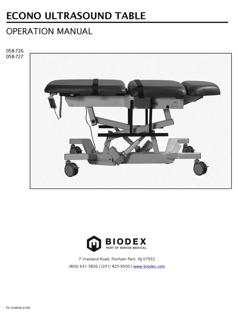
Clinton 85100 Maintenance manual

Examine Real Quality & Value™
OPERATION, CARE & MAINTENANCE
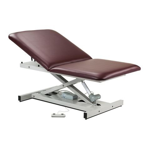
POWER IMAGING TABLES
Models 85100, 85200, 85300 & 85309
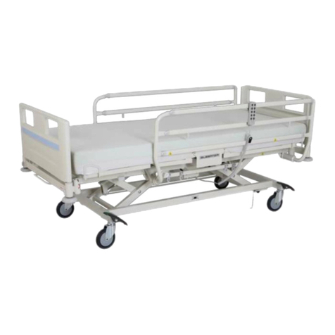
Model 85100 Model 85200 Model 85309
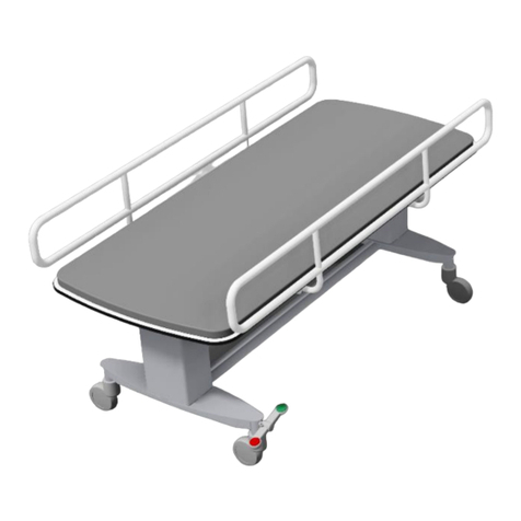
Model 85300

Thank you, for selecting and purchasing quality Clinton equipment. We are proud to serve your medical
equipment needs with products that deliver value and offer superior performance. Please read these instructions
carefully to insure your Clinton products are used and operated according to specifications and that they are
maintained to Clinton’s recommendations.
SPECIFICATIONS
THANK YOU
Examine Real Quality & Value™
Overall 72” 27” 18”–35”
Power Imaging Table with Drop Window
85100 Length Width Height Range
Power Imaging Table with Adjustable Backrest
Overall 72” 27” 18”–35”
Backrest 38” 27”
85200 Length Width Height Range
85300 Length Width Height Range
80330 Length Width Height Range
Overall 76” 27” 18”–35”
Backrest 38” 27”
Drop Section 13” 27”
Overall 76” 27” 18”–35”
Backrest 38” 27”
Drop Section 13”
Power Imaging Table with 3 Section Top
Multi-Use Power Imaging Table with Stirrups
Model Dimensions
108&3*."(*/(5"#-&4t.PEFMT
Upholstered Top Upholstered Top
HEAD-END
Adjustable Backrest
Actuator Lever
1 on each side
(models 85200,
85300 & 85309
only)
Top Frame
Center Leg
Center Axle
“H” Leg
“H” Leg Axle
BODY
Foot Drop Section
(models 85300 &
85309 only)
Stirrups
(model 85309
only)
Motor Assembly
Foot Drop Section
Lever
(models 85300 &
85309 only)
BASE
Foot Pedal
All models have a load capacity of 450 lbs.

CLEANING GUIDELINES
WARRANTY
ADJUSTMENTS
Motor Specifications
Duff Norton Motor (standard on all models)
The Duff Norton Motor is NOT UL listed for either the US or Canada. It IS, however, approved by the "CE" for
use in Europe.
120VAC 6 amps 8000N 1.8 min. of constant use out of every 18 min.
Push Duty Cycle
Duff Norton Motor Power Ratings
120VAC 8 amps 8000N 1 min. of constant use out of every 9 min.
Push Duty Cycle
SKF Motor Power Ratings
Clinton uses only premium vinyl for upholstery, however, care should be taken when cleaning to ensure that
the upholstery or color is not affected by the cleaning agent. Use only mild cleaning agents on upholstery.
Clinton recommends using a 1 to 1 mix of ammonia and water or a 1 to 4 mix of bleach and water, rinse
thoroughly with clean water and pat surface dry. This is not a guarantee and does not relieve the user from
responsibility of the proper and safe use of all cleaning agents. Test on inconspicuous area prior to using any
cleaning agent on upholstery's visible surface. Certain cleaning agents can be harmful to the surface.
Clinton Industries warrants manufactured products to be free of defects in materials, workmanship or design
under normal use for three years on all mechanical products and one year on all electric equipment, from the
date of purchase. This warranty does not include damage resulting from accident, abuse or misuse, alteration,
or negligence of the product and expressly excludes normal wear of parts (including but not limited to vinyl).
Contact Clinton for full warranty details.
BACKREST (models 85200, 85300, & 85309 only)
The backrest can be adjusted from either side of
the table using the backrest actuator.Rotate the
actuator towards the backrest to adjust. Always use
your hand on top of the upholstered top to move
the backrest up or down. The backrest cylinder is
pressurized in the up position only and requires
force to return it to the down position.
SKF Motor (optional on all models)
The SKF Motor IS UL/CSA listed via cURus listing. It meets all qualifications for both the US and Canada AND
60601-1 Standards at the component level.
Backrest Actuator
Backrest Cylinder
Adjusting Nuts
Backrest
Cylinder

BACKREST CYLINDER REPLACEMENT (models 85200, 85300 & 85309 only)
Remove cotter pin. Then remove
the slide-out pin. Position tab locat-
ed on the adjustment bar against
cylinder pin.
Align holes in cylinder bracket with holes in table bracket by adjusting
the angle until the holes line up. Install slide-out pin through holes and
replace cotter pin.
Finished view of cylinder assembly.
The backrest cylinder is replaceable in the field by following these simple directions below.
STIRRUPS (model 85309 only)
Stirrups are shown in the stored position in photo below at left. When extended, stirrups have two width
positions. Position 1 is the narrowest and Position 2 the widest. The length of the stirrups can be adjusted by
moving the stirrup slider to the desired location. When the patient applies foot pressure to the stirrup, it will
automatically lock into position. To return the stirrups to the stored position, fold the stirrup over onto the
slider bar and slide BOTH towards the head end of the table. The stirrup will store under the upholstered top.
ADJUSTMENTS (continued)
Stirrup
Stirrup
Slider
Stirrups in the stored position Stirrup positions
Stirrup Position 1
Stirrup Position 2
Cylinder Pin
Tab

FOOT DROP SECTION (models 85300 & 85309 only)
The Foot drop section is located at the foot-end of the table and is shown below at left in a semi-extended
position. The foot drop section can be raised and lowered using the foot drop section levers on either side of the
table. To lower the foot drop section, place your hand under the upholstered top of the foot drop section and
move the lever forward towards the foot-end of the table. The lever must be kept in the forward position while
gently lowering the foot drop section. To raise the drop section, place your hand under the upholstered top and
gently lift. The foot drop section levers will automatically move forward and the foot drop section will lock into
position wherever the lifting motion is stopped.
ADJUSTMENTS (continued)
Drop Section in the semi-raised position Drop Section in the down position
DROP WINDOW (all models)
The drop window should only be opened or closed
when the backrest is in the DOWN position. To
open the window, unscrew the slider lock knob one
tuen to the left (counterclockwise). Move the slider
pass the window area and gently lower the drop
window. To close the drop window, raise the win-
dow flush with the top, move the slider back over
the drop window. Secure the slider in place by
turning the slider lock knob one turn to the right
(clockwise).
Drop
Window
Slider
Slider Lock

TROUBLE SHOOTING
ADJUSTMENTS
PROBLEM: Table is squeaking.
SOLUTION: Lubricate the table at designated points using Molykote G-0052Fg grease.
See drawing below for lubrication locations.
Slide Block, 4 total (Base and Top Frame)
Lubricate using
Molykote G-0052Fg
grease, top and bottom contact points.
Base
Top Frame
End Plug
Back Rest
Back Rest Actuator Arm
Back Rest Cylinder
Foot Lift Actuator
Arm
Motor
Center Axle
Lubricate using
Molykote G-0052Fg
grease.
Base Axle
Top Frame Axle
OPTIONAL LOCKING CASTERS (all models)
Locking casters are an option on all models. The locking mechanism can be engaged by using your foot to
depressing the tab located at the rear of each caster. This locks the swivel of the caster and acts as a brake to
minimize movement of the wheel. ALL FOUR CASTERS MUST BE LOCKED TO ENSURE MINIMAL MOVEMENT
OF THE TABLE. Casters can be added or removed in the field.
Caster in the mobile position. Caster in the lock position.
(continued)

TROUBLE SHOOTING
PROBLEM: Table height adjustment will not work properly.
SOLUTION: Make sure the table is connected to a working electrical outlet. Inspect all power cords
for cuts or breaks that would interfere with the electrical connection. Check to make certain foot
pedal cord is properly and securely plugged into motor. If after checking all these areas, the table will
not operate, or operates improperly, call a technician, or call Clinton Industries at 800-441-9131 for
assistance.
REMOVAL OF THE MOTOR FOR SERVICE
The motor assembly is located at the foot-end of the table on the base. Next, detach the motor
assembly. If possible, raise the table to its highest position. Raising the table will make it easier to
remove the motor mount bolts. Using help, lower the table onto its side onto a protective surface
such as a blanket or other material that will not harm the upholstered top. Remove the foot pedal
controller by unplugging the DIN plug on the side of the motor. Carefully remove the upper and
lower motor mount bolts to free the motor assembly.
Upper Motor Mount
Motor Assembly
Foot Pedal DIN Plug
Lower Motor Mount
PROBLEM: Backrest does not function properly.
SOLUTION: If the headrest does not remain flat in
the down position, loosen nut “A” and
tighten nut “B.”
If headrest does not move at all, loosen
nut “B” and tighten nut “A.”
After proper function has been achieved,
tighten both nuts.
Nut A
Nut B
(continued)

© Copyright 2012, Clinton Industries, Inc.
This manual suits for next models
3
Table of contents
Other Clinton Medical Equipment manuals
