manuals.online logo
Brands
  1. Home
  2. •
  3. Brands
  4. •
  5. Cobra
  6. •
  7. Motorcycle Accessories
  8. •
  9. Cobra Fi2000 PowrPro Black User manual

Cobra Fi2000 PowrPro Black User manual

®23801 E. La Palma Ave., Yorba Linda, Ca 92887 Ph. 714.692.8180, Fax. 714.692.5016
www.cobrausa.com
04/16
1
DOCUMENT NO. 0017 REV. A
DISCLAIMER: NOT LEGAL FOR SALE OR USE IN CALIFORNIA ON ANY POLLUTION CONTROLLED
MOTOR VEHICLES.
Items Supplied >
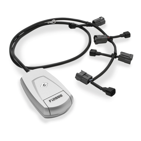
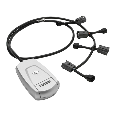
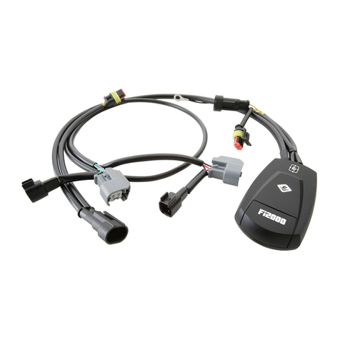
1 –Powrpro Black Fuel Injection Module
2 –Zip Ties 6”
1 –Zip Tie 8”
1 –Velcro Strip
Application(s) >
HARLEY V-ROD 2008 - 2010
Instruction Manual >
Read all instructions carefully and completely before installing your new POWRPRO module. It is
recommended that a qualified mechanic or technician install this product.
1. Flip up seat, to gain access to radiator reservoir area.
2. Remove Dzus fastener to remove simulated fuel tank cover, over airbox housing. Depending on
which model V-Rod is being worked on, the front shrouds covering the upper front frame section may
also need to be removed.
3. Place Fi2000 in under-seat area, run fuel injector connector harness up right side frame rail between
top right frame rail, and radiator overflow tank, see Figure 1. At the rear of the airbox, route the
harness below the airbox, and downward next to the inner radiator hose. Unplug both stock fuel
injector connectors, on the front and rear injectors between the engine cylinders, see Figure 2.
These are disconnected, by depressing the metal springs that are on the end of each female
connector. The stock female connectors are marked “F” and “R”, noting which connector goes to the
front and rear injector, be sure to pay attention to this. Now connect the longer male Fi2000
connector to the front female H.D. connector. Plug shorter Fi2000 male connector into the stock rear
female H.D. connector. Then plug the longer female Fi2000 connector onto the front stock H.D.
injector. Plug the shorter Fi2000 female connector onto the rear injector. Each injector connector pair
should rest underneath each respective injector.
4. Locate the rear oxygen sensor connector and follow the harness up to the under-seat area behind the
radiator overflow tank. Pull the stock connectors up from below the overflow tank and disconnect, see
Figure 1. The shorter Fi2000 Oxygen sensor harness with male and female connectors will plug into
each of these stock male and female connectors. Tuck the connectors back underneath the bracket
behind the radiator overflow tank.
5. Route the front oxygen sensor harness along the right upper frame rail as was previously done with
the fuel injector connector harness. Continue routing the harness forward along the frame rail past the
radiator overflow tank, and up past the airbox. Route the harness in front of the airbox, and over the
top of the airbox intake snorkel, behind the headstay. Remove the left front frame/tank cover to gain
access to the electrical connections above the front cylinderhead; removal of this cover may vary
depending on which model V-Rod is having the module installed on it. Route the front Fi2000 O2
sensor harness from the headstay area, down towards, the left front frame rail, and continue routing
the harness along the inside of the frame rail towards the radiator and left footpeg mounting boss.
Now locate the front oxygen sensor on the front headpipe, and trace the oxygen sensor harness back
to the connectors tucked between the left front frame rail and plastic radiator shroud, see Figure 3.
Continued to next page!
692-1613B
Page 1 of 3
®23801 E. La Palma Ave., Yorba Linda, Ca 92887 Ph. 714.692.8180, Fax. 714.692.5016
www.cobrausa.com
04/16
2
Instruction Manual >
692-1613B
Page 2 of 3
5. Continued: Pull these connectors out, and disconnect them. Plug the corresponding Fi2000
connectors into each of the stock male and female connectors, and tuck the connectors back in
between the frame rail and plastic shroud. Zip tie harness to left front frame rail to secure harness,
see Figure 4, and reinstall the frame tank cover previously removed.
6. Route ground wire from Fi2000 module along fuel injector harness to left rear side of rear cylinder
head, remove bolt from valve cover, and place through wire eyelet and reinstall bolt, being sure to
torque to factory specifications.
7. Remove the backing from the Velcro and attach the Fi2000 to the frame cross member as shown in
Figure 1.
8. Ziptie the Fi2000 Fuel injector and Oxygen sensor harness to the existing harness along the upper
right frame rail and radiator overflow tank.
9. Verify that the module has power and connections have been made correctly; watch the clear
window on the FI housing and turn "ON" the key ignition and set the handlebar run switch to "ON",
confirm that the Red LED turns on. On some models the Red light will turn off after 4-5 seconds as
the fuel pump cycles off, which is OK. If you do not see a Red light, it may be necessary to wait for
the alarm to reset (if applicable) and try again. Also confirm the side stand is up, bike is in neutral,
and clutch is in. Start the bike and confirm the LED remains on solid Red. NOTE: Make sure ignition
is turned off before attempting to change any Fi2000 harness connections if no Red light is seen.
For access to the Blue Tooth Tuning App on the module, please download the PowrPro Black App to
your smart device, Android 4.3 & later or Apple iOS 5.0 & later operating systems. Once the app is
installed, make sure the motorcycle is in neutral and start the engine, use the connect button within
the app and the Blue light on the Fi module window will light up during pairing connection and remain
solid Blue while paired and connected with respective Android or Apple Device. Once the app has
been used and settings saved and disconnected through the app, the Blue light will turn off, and the
PowrPro Black will be ready for continued service on the motorcycle.
10. Reinstall the simulated fuel tank cover and tighten Dzus fastener. Lower the seat and be sure all
hardware is tightened to factory specifications.
DOCUMENT NO. 0018 REV. A
FIGURE 1
REAR OXYGEN SENSOR
CONNECTOR,
CONNECTED WITH Fi2000
OXYGEN SENSOR
HARNESS
Fi2000
MOUNTING
LOCATION
HARNESS ROUTING TO
INJECTOR CONNECTORS
AND FRONT O2SENSOR
CONNECTOR
SECURE WITH
ZIPTIE AT THIS
LOCATION
®23801 E. La Palma Ave., Yorba Linda, Ca 92887 Ph. 714.692.8180, Fax. 714.692.5016
www.cobrausa.com
04/16
3
Instruction Manual >
692-1613B
Page 3 of 3
DOCUMENT NO. 0018 REV. A
FIGURE 2
FRONT FEMALE INJECTOR
CONNECTOR WITH
LONGER MALE Fi2000
CONNECTOR
REAR FEMALE INJECTOR
CONNECTOR WITH SHORTER
MALE Fi2000 CONNECTORS
LONGER Fi2000
FEMALE CONNECTOR
ON FRONT CYLINDER
INJECTOR
NOTE: REAR INJECTOR
AND Fi2000 CONNECTION
NOT VISIBLE
FIGURE 3
SECURE HARNESS
WITH 8” ZIP TIE AT
THIS LOCATION
FRONT Fi2000
OXYGEN
SENSOR
HARNESS
ROUTING
LEFT FRONT
FRAME RAIL
AIR INTAKE
SNORKEL
Fi2000 O2MALE
CONNECTOR
WITH FEMALE O2
CONNECTOR
FRONT Fi2000
OXYGEN
SENSOR
HARNESS
LEFT FRONT
FRAME RAIL
FIGURE 4
DISCLAIMER: NOT LEGAL FOR SALE OR USE IN CALIFORNIA ON ANY POLLUTION CONTROLLED
MOTOR VEHICLES.

Other Cobra Motorcycle Accessories manuals

Cobra 602-2611 User manual

Cobra

Cobra 602-2611 User manual

Cobra 602-2600 User manual

Cobra

Cobra 602-2600 User manual

Cobra 06-3750 User manual

Cobra

Cobra 06-3750 User manual

Cobra 4918 User manual

Cobra

Cobra 4918 User manual

Cobra 6468B User manual

Cobra

Cobra 6468B User manual

Cobra Fi2000 User manual

Cobra

Cobra Fi2000 User manual

Cobra 602-1103B User manual

Cobra

Cobra 602-1103B User manual

Cobra P259643 User manual

Cobra

Cobra P259643 User manual

Cobra 602-2027 User manual

Cobra

Cobra 602-2027 User manual

Cobra Ride Loud User manual

Cobra

Cobra Ride Loud User manual

Cobra 602-2500 User manual

Cobra

Cobra 602-2500 User manual

Cobra HONDA VLX 600 User manual

Cobra

Cobra HONDA VLX 600 User manual

Cobra FXLR User manual

Cobra

Cobra FXLR User manual

Cobra 602-2615 User manual

Cobra

Cobra 602-2615 User manual

Cobra Fi2000 User manual

Cobra

Cobra Fi2000 User manual

Cobra 06-0225-01B User manual

Cobra

Cobra 06-0225-01B User manual

Cobra 01-1105 User manual

Cobra

Cobra 01-1105 User manual

Cobra POWRPRO Fi2000 User manual

Cobra

Cobra POWRPRO Fi2000 User manual

Cobra PowrFlo 06-0467-01 User manual

Cobra

Cobra PowrFlo 06-0467-01 User manual

Cobra Fi200R User manual

Cobra

Cobra Fi200R User manual

Cobra 602-3000 User manual

Cobra

Cobra 602-3000 User manual

Cobra 02-6468 User manual

Cobra

Cobra 02-6468 User manual

Cobra 602-2000B User manual

Cobra

Cobra 602-2000B User manual

Cobra FLHC 2018 User manual

Cobra

Cobra FLHC 2018 User manual

Popular Motorcycle Accessories manuals by other brands

Guglatech M07006 instructions

Guglatech

Guglatech M07006 instructions

Makita DCV200 instruction manual

Makita

Makita DCV200 instruction manual

KTM 60112092010 Information

KTM

KTM 60112092010 Information

Yoshimura Street Series manual

Yoshimura

Yoshimura Street Series manual

VR EQUIPMENT VREQH2 user manual

VR EQUIPMENT

VR EQUIPMENT VREQH2 user manual

Dynojet Power commander V installation instructions

Dynojet

Dynojet Power commander V installation instructions

Saddlemen 808-07-0042 User's guide & installation instructions

Saddlemen

Saddlemen 808-07-0042 User's guide & installation instructions

R&G CP0550BL Fitting instructions

R&G

R&G CP0550BL Fitting instructions

Crivit EH-1430 Instructions for use

Crivit

Crivit EH-1430 Instructions for use

KTM Power Parts 60307940000 Information

KTM Power Parts

KTM Power Parts 60307940000 Information

Wolfman Monarch Pass Mounting instructions

Wolfman

Wolfman Monarch Pass Mounting instructions

R&G LP0308BK Fitting instructions

R&G

R&G LP0308BK Fitting instructions

Ducati KIT Top Case 1106 Assembly instructions

Ducati

Ducati KIT Top Case 1106 Assembly instructions

Kuryakyn ISO-SweptWing 4463 installation instructions

Kuryakyn

Kuryakyn ISO-SweptWing 4463 installation instructions

Custom Dynamics CD-FORK-BCM-AB installation instructions

Custom Dynamics

Custom Dynamics CD-FORK-BCM-AB installation instructions

Dynojet POWER  COMMANDER FC installation instructions

Dynojet

Dynojet POWER COMMANDER FC installation instructions

SUOMY MrJump User instructions

SUOMY

SUOMY MrJump User instructions

rizoma ZDM131 user manual

rizoma

rizoma ZDM131 user manual

manuals.online logo
manuals.online logoBrands
  • About & Mission
  • Contact us
  • Privacy Policy
  • Terms and Conditions

Copyright 2025 Manuals.Online. All Rights Reserved.