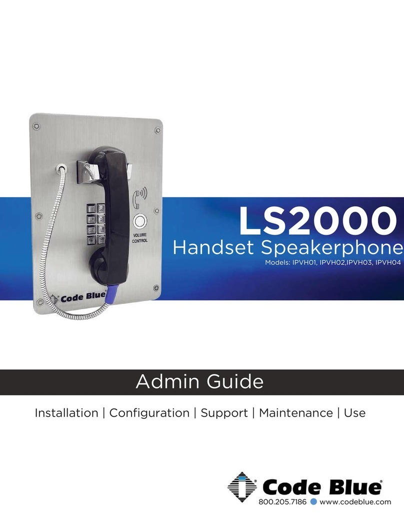
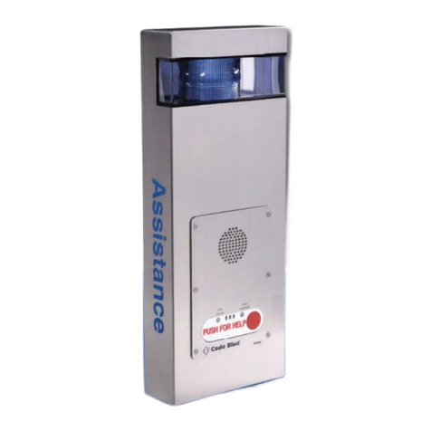
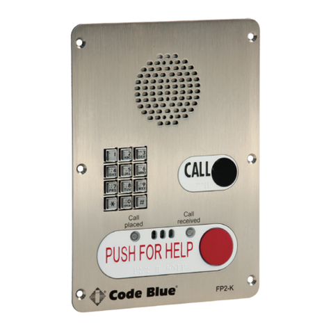
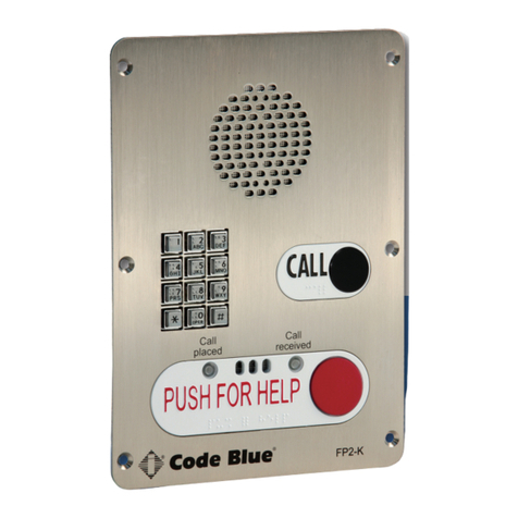
Code Blue CB RT Service manual

800.205.7186 •www.codeblue.com
Administrator Guide
Installation | Configuration | Operation | Troubleshooting
CB RT

Code Blue •259 Hedcor Street •Holland, MI 49423 USA •800.205.7186 •www.codeblue.com GU-163-Apage 2 of 27
CB RT
Administrator Guide
WARNING
ONLY QUALIFIED PERSONNEL SHOULD INSTALL THESE UNITS. THE INSTALLATION
SHOULD CONFORM TO ALL LOCAL CODES. IN SOME COUNTRIES, A CERTIFIED ELECTRI-
CIAN MAY BE REQUIRED.
NOTICE TO USERS
Copyright © Code Blue Corporation. All rights reserved. This guide or software described herein, in
whole or part, shall not be reproduced, translated or reduced to any machine-readable form without
prior written approval from Code Blue Corporation.
CODE BLUE CORPORATION PROVIDES NO WARRANTY WITH REGARD TO THIS GUIDE, THE
SOFTWARE OR OTHER INFORMATION CONTAINED HEREIN AND HEREBY EXPRESSLY DIS-
CLAIMS ANY IMPLIED WARRANTIES OF MERCHANTABILITY OR FITNESS FOR ANY PARTICU-
LAR PURPOSE WITH REGARD TO THIS GUIDE, THE SOFTWARE OR SUCH OTHER INFORMA-
TION. IN NO EVENT SHALL CODE BLUE CORPORATION BE LIABLE FOR ANY INCIDENTAL,
CONSEQUENTIAL, OR SPECIAL DAMAGES, WHETHER BASED ON TORT, CONTRACT, OR
OTHERWISE, ARISING OUT OF OR IN CONNECTIONS WITH THIS GUIDE, THE SOFTWARE
OR OTHER INFORMATION CONTAINED HEREIN OR THE USE THEREOF.
Code Blue Corporation reserves the right to make any modications to this guide or the information
contained herein at any time without notice. The software described herein may also be governed
by the terms of a separate user license agreement.
Code Blue®is a registered trademark of Code Blue Corporation.

Code Blue •259 Hedcor Street •Holland, MI 49423 USA •800.205.7186 •www.codeblue.com GU-163-Apage 3 of 27
CB RT
Administrator Guide
Table of Contents
Section Page
2 Introduction.................................................................................... 4
3 Getting Started............................................................................... 5
4 Spare Parts..................................................................................... 6
5 Technical Features......................................................................... 7
6 Exploded View................................................................................ 8
7 Power Requirements.....................................................................10
8 CB RT Installation Instructions....................................................13
9 Overhead Camera Mount Installation Instructions.....................15
10 Standard Wiring.............................................................................17
11 PoE Wiring......................................................................................18
12 Serial Number Location................................................................19
13 Line Power Installation Instructions........................................... 20
14 S-1000/S-1050 Installation Instructions.......................................21
15 Software Conguration.................................................................23
16 Maintenance...................................................................................24
17 Warranty..........................................................................................26
18 Download Information...................................................................27

Code Blue •259 Hedcor Street •Holland, MI 49423 USA •800.205.7186 •www.codeblue.com GU-163-Apage 4 of 27
CB RT
Administrator Guide
2 Introduction
Thank you for choosing the CB RT for your Code Blue application.
The CB RT is an economical pedestal Help Point® highlighted by a high intensity LED beacon/
strobe light that provides exceptional visibility and acts as a deterrent to potential crime. This blue
light emergency tower provides direct communication with rst responders and can extend security
efforts to walkways, parking lots, open campus areas and more.
CB RT towers are easily recognized throughout a full 360-degree area. The user friendly lighted
faceplate and the integral LED combo strobe ensures rapid location in an open environment and
easily identi able by security when activated.
The exclusive analog InterAct and VoIP speakerphones are designed for maximum reliability,
vandal resistance, auxiliary functions, mass noti cation control, and fault monitoring and reporting
capability. (See IA4100 or IP5000 guides for more information.)
Our unmistakable craftsmanship makes our Help Points®the most rugged on the market,
withstanding the punishment of natural and man-made disasters. With durable construction, our
pedestal units can meet any requirement or purpose. CB RT tower units have a rugged steel
construction, engineering grade re ective graphics and weather, UV and graf ti resistant paint.
Lighting with a high-powered, 270 lumens / 92 candela LED blue beacon/strobe.
Other options include:
• IP and analog phones
• Overhead Camera Mount
This guide contains all of the CB RT tower information. This manual contains
a general overview of the Code Blue CB RT Tower options and its application,
installation and wiring.
CB RT
CB RT

Code Blue •259 Hedcor Street •Holland, MI 49423 USA •800.205.7186 •www.codeblue.com GU-163-Apage 5 of 27
CB RT
Administrator Guide
3 Getting Started
Basic Install Instructions
1. EIA/TIA, ANSI, CSA and BICSI cabling or similar standards shall be adhered to for proper
operation of Code Blue communication devices connected to copper or ber infrastructures.
Communications cable and electrical cable in the same conduit is not an acceptable instal-
lation and shall not be supported. Analog phones require a minimum of 23mA for proper
operation (26-29mA recommended).
2. Each analog speakerphone requires its own phone line or PBX extension. Multiple units
shall not be supported.
3. Speakerphones require programming before operation. Consult the User Guide or Admin-
istrator Guide enclosed with the unit or go to www.codeblue.com > Support > Downloads to
read or download manuals.
4. If you are installing IP speakerphones, please read the appropriate manuals and consult
with your Network Administrator.
5. Size electrical wiring based on length of run.
6. Consult the enclosed document packet for internal wiring instructions.
What’s Included
Quantity Part Description
1 Anchor Bolt Kit (4 L-Bolts, 8 Washers, 4 Hex Nuts, 1 Cardboard Template)
1 Security Bit
2 Access Door Screws
1 URL listing sheet of Installation, Programming, Wiring & Warranty locations
CB RT Tools Required
1. Ladder to reach the top of the unit
2. Drill and security bit for removing and inserting security screws on phone and
access door
3. 11/8 socket set and extension for installing anchor bolts or Deck Mount Kits
4. Phillips head screwdriver and at head screwdriver

Code Blue •259 Hedcor Street •Holland, MI 49423 USA •800.205.7186 •www.codeblue.com GU-163-Apage 6 of 27
CB RT
Administrator Guide
4 Spare Parts
CB RT
Part Part Number
LED Strobe Light 40159
LED Faceplate Light 40196
Faceplate Screws 41544 (6 pack)
Access Door Screws 41545 (2 pack)
Analog Surge Suppressor 41471
IP Surge Suppressor 41421

Code Blue •259 Hedcor Street •Holland, MI 49423 USA •800.205.7186 •www.codeblue.com GU-163-Apage 7 of 27
CB RT
Administrator Guide
5 Technical Features
Specifications
• Height: 9’ (289.56 cm)
• Weight: 225 lbs. (102.06 kg)
• Width: 10” (21.90 cm)
• Depth: 8” (21.90 cm)
• Material & thickness: 0.1875” steel
• Access door: 15.88” x 7.88” (40.34 x 20.02 cm)
Power
• Standard: 12-24V AC/DC
• Optional: 120, 240, 277V AC
○PoE
Communication
• Speakerphone Options
○IP5000: Full duplex, SIP compatible VoIP phone.
○IA4100: Analog full duplex phone.
• Hardwire
Style
• Standard powder coat color: Safety Blue
• Optional wet coat colors: Dark Bronze, Gloss White, Gloss Black, Safety Blue, Safety Red,
Safety Yellow, Bright Silver
• Graphics text: Assistance, Emergency
• Graphics color: White
Lighting
• LED faceplate light
• Beacon/strobe
Compliance
• UL 2017
• NEMA 4
• ADA
Options
• Overhead camera mount

Code Blue •259 Hedcor Street •Holland, MI 49423 USA •800.205.7186 •www.codeblue.com GU-163-Apage 8 of 27
CB RT
Administrator Guide
6 CB RT Exploded View
DISCLAIMER: Product design and component use subject to change without notice. Product shown reasonably represents current offering and
is intended to assist in component identication. Reference the model and serial number from the unit ID tag and contact manufacturer to conrm
replacement part version and availability.
ITEM # DESCRIPTION QTY
1Tower Assy Painted 1
2 LED Blue Beacon Strobe 1
3 Standard / Custom Graphic 2
4DIN Rail Assy 1
5 114” Harness Connector 1
6 LED Faceplate Light 1
7 Model/Serial Number Graphic 1
8 Inspected and Tested Graphic 1
9 Access Door 1
10 Security Screws 2
11 Diamond Graphic 1
113.51
10.00 8.00
2
11
3
8
7
9
1
4
5
6
10

Code Blue •259 Hedcor Street •Holland, MI 49423 USA •800.205.7186 •www.codeblue.com GU-163-Apage 9 of 27
CB RT
Administrator Guide
113.51
10.00 8.00
2
11
3
8
7
9
1
4
5
6
10
2.00
39.09
12.41
108.00
113.51
BASE PLATE
3.44
2.13
4.26
4.00
6.00
45° TYP
11.06
16.00
105.50
FRONT VIEW
SIDE VIEW
BASE PLATE DETAIL
SCALE 1:8
BACK VIEW
8.00
10.00
Bottom View

Code Blue •259 Hedcor Street •Holland, MI 49423 USA •800.205.7186 •www.codeblue.com GU-163-Apage 10 of 27
CB RT
Administrator Guide
7 Power Requirements (2020)
(The following power requirements include the CB RT and also ALL OTHER Code Blue units.)
Component Specs
Faceplates Voltage Max Current Max Watts Norm Current Norm Watts KWHrs
High Votage AC Components Voltage Current Watts KWHrs
IA4100 24V AC 0.40 9.60 0.22 5.28 0.13
Multi-Tap Power Supply 120V AC 1.75A/210VAC 210 5.04
12V DC 0.90 10.80 0.39 4.68 0.11
Din Rail Power Supply 120V AC 1.2A/115VAC 115 2.76
24V DC 0.90 21.60 0.39 9.36 0.22
Heater -AED 120V AC 1.6 192 4.61
IP5000 24V AC 0.10 2.40 0.07 1.68 0.04
DC - PS AED 120V AC 2.6 312 7.49
12V DC 0.19 2.28 0.15 1.8 0.04
PAS Amp 120V AC 3.83 459.6 11.03
24V DC 0.19 4.56 0.15 3.6 0.09
Centry®12V DC 0.50 6.00 0.38 4.56 0.11
Lights Voltage Max Current Max Watts Norm Current Norm Watts KWHrs
High Voltage Models Voltage Current Watts KWHrs
S-1000 LED Strobe 24V AC 2.80 67.20 0.22 5.28 0.13
CB 1 AED 120V AC 3.35 402 9.6
12V DC 0.26 3.12 0.24 2.88 0.07
CB 2 AED 120V AC 3.35 402 9.6
24V DC 0.26 6.24 0.24 5.76 0.14
CB 1 PAS 120V AC 3.83 460 11
A-700 Area Light 24 VAC 1.80 43.20 0.83 19.92 0.48
CB 5 PAS 120V AC 3.33 400 9.6
12V DC 2.68 32.16 0.38 4.56 0.11
CB 1-s w/ NightCharge®120V AC 2.5 300 2.4
24V DC 2.68 64.32 0.38 9.12 0.22
CB 4-u w/ NightCharge®120V AC 2.5 300 2.4
S-1050 LED Strobe w/ Photocell 24V AC 2.80 67.20 0.22 5.28 0.13
12V DC 2.68 32.16 0.38 4.56 0.11
24V DC 2.68 64.32 0.38 9.12 0.22
LED Light Bar 24V AC 0.04 0.96 0.04 0.96 0.02
12V DC 0.04 0.48 0.04 0.48 0.01
24V DC 0.04 0.96 0.04 0.96 0.02
WM-180 PAS with LED Strobe 24V AC 7.30 175.20 2.10 50.4 1.21
Common Configurations
Models With IA4100 Faceplate Voltage Current Watts KWHrs Models With IP5000 Faceplate Voltage Current Watts KWHrs
CB 1-e 24V AC 0.48 11.52 0.28 CB 1-e 24V AC 0.33 7.92 0.19
12V DC 0.67 8.04 0.19 12V DC 0.43 5.16 0.12
24V DC 0.67 16.08 0.39 24V DC 0.43 10.32 0.25
CB 1-s 24V AC 1.31 31.44 0.75 CB 1-s 24V AC 1.16 27.84 0.67
12V DC 1.05 12.60 0.30 12V DC 0.81 9.72 0.23
24V DC 1.05 25.20 0.60 24V DC 0.81 19.44 0.47
CB 5-s/5-p 24V AC 0.48 11.52 0.28 CB 5-s/5-p 24V AC 0.33 7.92 0.19
12V DC 0.67 8.04 0.19 12V DC 0.43 5.16 0.12
24V DC 0.67 16.08 0.39 24V DC 0.43 10.32 0.25
CB 9-s 24V AC 0.26 6.24 0.15 CB 9-s 24V AC 0.11 2.64 0.06
12V DC 0.43 5.16 0.12 12V DC 0.19 2.28 0.05
24V DC 0.43 10.32 0.25 24V DC 0.19 4.56 0.11
CB 2-e 24V AC 0.44 10.56 0.25 CB 2-e 24V AC 0.29 6.96 0.17
12V DC 0.63 7.56 0.18 12V DC 0.39 4.68 0.11
24V DC 0.63 15.12 0.36 24V DC 0.39 9.36 0.22
CB 2-a 24V AC 0.48 11.52 0.28 CB 2-a 24V AC 0.33 7.92 0.19
12V DC 0.67 8.04 0.19 12V DC 0.43 5.16 0.12
24V DC 0.67 16.08 0.39 24V DC 0.43 10.32 0.25
CB 2-s 24V AC 1.31 31.44 0.75 CB 2-s 24V AC 1.16 27.84 0.67
12V DC 1.05 12.60 0.30 12V DC 0.81 9.72 0.23
24V DC 1.05 25.20 0.60 24V DC 0.81 19.44 0.47
CB 2-e W/ PAS 24V AC 6.44 154.56 3.71 CB 2-e / PAS 24V AC 6.44 154.56 3.71
CB 4-s 24V AC 0.22 5.28 0.13 CB 4-s 24V AC 0.07 1.68 0.04
12V DC 0.39 4.68 0.11 12V DC 0.15 1.8 0.04
24V DC 0.39 9.36 0.22 24V DC 0.15 3.6 0.09
CB 4-r 24V AC 0.26 6.24 0.15 CB 4-r 24V AC 0.11 2.64 0.06
12V DC 0.43 5.16 0.12 12V DC 0.19 2.28 0.05
24V DC 0.43 10.32 0.25 24V DC 0.19 4.56 0.11
CB 4-u 24V AC 0.26 6.24 0.15 CB 4-u 24V AC 0.11 2.64 0.06
12V DC 0.43 5.16 0.12 12V DC 0.19 2.28 0.05
24V DC 0.43 10.32 0.25 24V DC 0.19 4.56 0.11
Surface Mount/Flush Mount 24V AC 0.22 5.28 0.13 Surface Mount/Flush Mount 24V AC 0.07 1.68 0.04
12V DC 0.39 4.68 0.11 12V DC 0.15 1.8 0.04
24V DC 0.39 9.36 0.22 24V DC 0.15 3.6 0.09
CB RT 24V AC 1.10 26.33 0.63 CB RT 24V AC 1.21 28.96 0.70
12V DC 0.81 9.75 0.23 12V DC 1.03 12.37 0.30
24V DC 1.61 38.57 0.93 24V DC 1.13 27.10 0.65

Code Blue •259 Hedcor Street •Holland, MI 49423 USA •800.205.7186 •www.codeblue.com GU-163-Apage 11 of 27
CB RT
Administrator Guide
Power Requirements continued
Component Specs
Faceplates Voltage Max Current Max Watts Norm Current Norm Watts KWHrs High Votage AC Components Voltage Current Watts KWHrs
IA4100 24V AC 0.40 9.60 0.22 5.28 0.13 Multi-Tap Power Supply 120V AC 1.75A/210VAC 210 5.04
12V DC 0.90 10.80 0.39 4.68 0.11 Din Rail Power Supply 120V AC 1.2A/115VAC 115 2.76
24V DC 0.90 21.60 0.39 9.36 0.22 Heater -AED 120V AC 1.6 192 4.61
IP5000 24V AC 0.10 2.40 0.07 1.68 0.04 DC - PS AED 120V AC 2.6 312 7.49
12V DC 0.19 2.28 0.15 1.8 0.04 PAS Amp 120V AC 3.83 459.6 11.03
24V DC 0.19 4.56 0.15 3.6 0.09
Centry®12V DC 0.50 6.00 0.38 4.56 0.11
Lights Voltage Max Current Max Watts Norm Current Norm Watts KWHrs High Voltage Models Voltage Current Watts KWHrs
S-1000 LED Strobe 24V AC 2.80 67.20 0.22 5.28 0.13 CB 1 AED 120V AC 3.35 402 9.6
12V DC 0.26 3.12 0.24 2.88 0.07 CB 2 AED 120V AC 3.35 402 9.6
24V DC 0.26 6.24 0.24 5.76 0.14 CB 1 PAS 120V AC 3.83 460 11
A-700 Area Light 24 VAC 1.80 43.20 0.83 19.92 0.48 CB 5 PAS 120V AC 3.33 400 9.6
12V DC 2.68 32.16 0.38 4.56 0.11
CB 1-s w/ NightCharge®120V AC 2.5 300 2.4
24V DC 2.68 64.32 0.38 9.12 0.22
CB 4-u w/ NightCharge®120V AC 2.5 300 2.4
S-1050 LED Strobe w/ Photocell 24V AC 2.80 67.20 0.22 5.28 0.13
12V DC 2.68 32.16 0.38 4.56 0.11
24V DC 2.68 64.32 0.38 9.12 0.22
LED Light Bar 24V AC 0.04 0.96 0.04 0.96 0.02
12V DC 0.04 0.48 0.04 0.48 0.01
24V DC 0.04 0.96 0.04 0.96 0.02
WM-180 PAS with LED Strobe 24V AC 7.30 175.20 2.10 50.4 1.21
Common Configurations
Models With IA4100 Faceplate Voltage Current Watts KWHrs
Models With IP5000 Faceplate Voltage Current Watts KWHrs
CB 1-e 24V AC 0.48 11.52 0.28
CB 1-e 24V AC 0.33 7.92 0.19
12V DC 0.67 8.04 0.19
12V DC 0.43 5.16 0.12
24V DC 0.67 16.08 0.39
24V DC 0.43 10.32 0.25
CB 1-s 24V AC 1.31 31.44 0.75
CB 1-s 24V AC 1.16 27.84 0.67
12V DC 1.05 12.60 0.30
12V DC 0.81 9.72 0.23
24V DC 1.05 25.20 0.60
24V DC 0.81 19.44 0.47
CB 5-s/5-p 24V AC 0.48 11.52 0.28
CB 5-s/5-p 24V AC 0.33 7.92 0.19
12V DC 0.67 8.04 0.19
12V DC 0.43 5.16 0.12
24V DC 0.67 16.08 0.39
24V DC 0.43 10.32 0.25
CB 9-s 24V AC 0.26 6.24 0.15
CB 9-s 24V AC 0.11 2.64 0.06
12V DC 0.43 5.16 0.12
12V DC 0.19 2.28 0.05
24V DC 0.43 10.32 0.25
24V DC 0.19 4.56 0.11
CB 2-e 24V AC 0.44 10.56 0.25
CB 2-e 24V AC 0.29 6.96 0.17
12V DC 0.63 7.56 0.18
12V DC 0.39 4.68 0.11
24V DC 0.63 15.12 0.36
24V DC 0.39 9.36 0.22
CB 2-a 24V AC 0.48 11.52 0.28
CB 2-a 24V AC 0.33 7.92 0.19
12V DC 0.67 8.04 0.19
12V DC 0.43 5.16 0.12
24V DC 0.67 16.08 0.39
24V DC 0.43 10.32 0.25
CB 2-s 24V AC 1.31 31.44 0.75
CB 2-s 24V AC 1.16 27.84 0.67
12V DC 1.05 12.60 0.30
12V DC 0.81 9.72 0.23
24V DC 1.05 25.20 0.60
24V DC 0.81 19.44 0.47
CB 2-e W/ PAS 24V AC 6.44 154.56 3.71
CB 2-e / PAS 24V AC 6.44 154.56 3.71
CB 4-s 24V AC 0.22 5.28 0.13
CB 4-s 24V AC 0.07 1.68 0.04
12V DC 0.39 4.68 0.11
12V DC 0.15 1.8 0.04
24V DC 0.39 9.36 0.22
24V DC 0.15 3.6 0.09
CB 4-r 24V AC 0.26 6.24 0.15
CB 4-r 24V AC 0.11 2.64 0.06
12V DC 0.43 5.16 0.12
12V DC 0.19 2.28 0.05
24V DC 0.43 10.32 0.25
24V DC 0.19 4.56 0.11
CB 4-u 24V AC 0.26 6.24 0.15
CB 4-u 24V AC 0.11 2.64 0.06
12V DC 0.43 5.16 0.12
12V DC 0.19 2.28 0.05
24V DC 0.43 10.32 0.25
24V DC 0.19 4.56 0.11
Surface Mount/Flush Mount 24V AC 0.22 5.28 0.13
Surface Mount/Flush Mount 24V AC 0.07 1.68 0.04
12V DC 0.39 4.68 0.11
12V DC 0.15 1.8 0.04
24V DC 0.39 9.36 0.22
24V DC 0.15 3.6 0.09
CB RT 24V AC 1.10 26.33 0.63
CB RT 24V AC 1.21 28.96 0.70
12V DC 0.81 9.75 0.23
12V DC 1.03 12.37 0.30
24V DC 1.61 38.57 0.93
24V DC 1.13 27.10 0.65
Code Blue •259 Hedcor Street •Holland, MI 49423 USA •800.205.7186 •www.codeblue.com GU-163-Apage 12 of 27
CB RT
Administrator Guide
Power Requirements continued
Component Specs
Faceplates Voltage Max Current Max Watts Norm Current Norm Watts KWHrs High Votage AC Components Voltage Current Watts KWHrs
IA4100 24V AC 0.40 9.60 0.22 5.28 0.13 Multi-Tap Power Supply 120V AC 1.75A/210VAC 210 5.04
12V DC 0.90 10.80 0.39 4.68 0.11 Din Rail Power Supply 120V AC 1.2A/115VAC 115 2.76
24V DC 0.90 21.60 0.39 9.36 0.22 Heater -AED 120V AC 1.6 192 4.61
IP5000 24V AC 0.10 2.40 0.07 1.68 0.04 DC - PS AED 120V AC 2.6 312 7.49
12V DC 0.19 2.28 0.15 1.8 0.04 PAS Amp 120V AC 3.83 459.6 11.03
24V DC 0.19 4.56 0.15 3.6 0.09
Centry®12V DC 0.50 6.00 0.38 4.56 0.11
Lights Voltage Max Current Max Watts Norm Current Norm Watts KWHrs High Voltage Models Voltage Current Watts KWHrs
S-1000 LED Strobe 24V AC 2.80 67.20 0.22 5.28 0.13 CB 1 AED 120V AC 3.35 402 9.6
12V DC 0.26 3.12 0.24 2.88 0.07 CB 2 AED 120V AC 3.35 402 9.6
24V DC 0.26 6.24 0.24 5.76 0.14 CB 1 PAS 120V AC 3.83 460 11
A-700 Area Light 24 VAC 1.80 43.20 0.83 19.92 0.48 CB 5 PAS 120V AC 3.33 400 9.6
12V DC 2.68 32.16 0.38 4.56 0.11
CB 1-s w/ NightCharge®120V AC 2.5 300 2.4
24V DC 2.68 64.32 0.38 9.12 0.22
CB 4-u w/ NightCharge®120V AC 2.5 300 2.4
S-1050 LED Strobe w/ Photocell 24V AC 2.80 67.20 0.22 5.28 0.13
12V DC 2.68 32.16 0.38 4.56 0.11
24V DC 2.68 64.32 0.38 9.12 0.22
LED Light Bar 24V AC 0.04 0.96 0.04 0.96 0.02
12V DC 0.04 0.48 0.04 0.48 0.01
24V DC 0.04 0.96 0.04 0.96 0.02
WM-180 PAS with LED Strobe 24V AC 7.30 175.20 2.10 50.4 1.21
Common Configurations
Models With IA4100 Faceplate Voltage Current Watts KWHrs
Models With IP5000 Faceplate Voltage Current Watts KWHrs
CB 1-e 24V AC 0.48 11.52 0.28
CB 1-e 24V AC 0.33 7.92 0.19
12V DC 0.67 8.04 0.19
12V DC 0.43 5.16 0.12
24V DC 0.67 16.08 0.39
24V DC 0.43 10.32 0.25
CB 1-s 24V AC 1.31 31.44 0.75
CB 1-s 24V AC 1.16 27.84 0.67
12V DC 1.05 12.60 0.30
12V DC 0.81 9.72 0.23
24V DC 1.05 25.20 0.60
24V DC 0.81 19.44 0.47
CB 5-s/5-p 24V AC 0.48 11.52 0.28
CB 5-s/5-p 24V AC 0.33 7.92 0.19
12V DC 0.67 8.04 0.19
12V DC 0.43 5.16 0.12
24V DC 0.67 16.08 0.39
24V DC 0.43 10.32 0.25
CB 9-s 24V AC 0.26 6.24 0.15
CB 9-s 24V AC 0.11 2.64 0.06
12V DC 0.43 5.16 0.12
12V DC 0.19 2.28 0.05
24V DC 0.43 10.32 0.25
24V DC 0.19 4.56 0.11
CB 2-e 24V AC 0.44 10.56 0.25
CB 2-e 24V AC 0.29 6.96 0.17
12V DC 0.63 7.56 0.18
12V DC 0.39 4.68 0.11
24V DC 0.63 15.12 0.36
24V DC 0.39 9.36 0.22
CB 2-a 24V AC 0.48 11.52 0.28
CB 2-a 24V AC 0.33 7.92 0.19
12V DC 0.67 8.04 0.19
12V DC 0.43 5.16 0.12
24V DC 0.67 16.08 0.39
24V DC 0.43 10.32 0.25
CB 2-s 24V AC 1.31 31.44 0.75
CB 2-s 24V AC 1.16 27.84 0.67
12V DC 1.05 12.60 0.30
12V DC 0.81 9.72 0.23
24V DC 1.05 25.20 0.60
24V DC 0.81 19.44 0.47
CB 2-e W/ PAS 24V AC 6.44 154.56 3.71
CB 2-e / PAS 24V AC 6.44 154.56 3.71
CB 4-s 24V AC 0.22 5.28 0.13
CB 4-s 24V AC 0.07 1.68 0.04
12V DC 0.39 4.68 0.11
12V DC 0.15 1.8 0.04
24V DC 0.39 9.36 0.22
24V DC 0.15 3.6 0.09
CB 4-r 24V AC 0.26 6.24 0.15
CB 4-r 24V AC 0.11 2.64 0.06
12V DC 0.43 5.16 0.12
12V DC 0.19 2.28 0.05
24V DC 0.43 10.32 0.25
24V DC 0.19 4.56 0.11
CB 4-u 24V AC 0.26 6.24 0.15
CB 4-u 24V AC 0.11 2.64 0.06
12V DC 0.43 5.16 0.12
12V DC 0.19 2.28 0.05
24V DC 0.43 10.32 0.25
24V DC 0.19 4.56 0.11
Surface Mount/Flush Mount 24V AC 0.22 5.28 0.13
Surface Mount/Flush Mount 24V AC 0.07 1.68 0.04
12V DC 0.39 4.68 0.11
12V DC 0.15 1.8 0.04
24V DC 0.39 9.36 0.22
24V DC 0.15 3.6 0.09
CB RT 24V AC 1.10 26.33 0.63
CB RT 24V AC 1.21 28.96 0.70
12V DC 0.81 9.75 0.23
12V DC 1.03 12.37 0.30
24V DC 1.61 38.57 0.93
24V DC 1.13 27.10 0.65
Code Blue •259 Hedcor Street •Holland, MI 49423 USA •800.205.7186 •www.codeblue.com GU-163-Apage 13 of 27
CB RT
Administrator Guide
8 CB RT Installation Instructions
1.0 FOUNDATION - ANCHOR BOLT INSTALLATION INSTRUCTIONS
1.1 Conduit – Electrical and communication line conduit should be run through the center of the
foundation hole with a maximum combined diameter of three inches. A minimum of four inches
and a maximum of six inches of conduit is required above the nished grade level. To ensure
proper grounding, a ½-inch x 8-foot copper rod should be inserted in the center of the founda-
tion and tied to the steel enclosure. (Note: Follow all national and local codes governing this
installation.)
1.1 Pour the foundation – The foundation should be at least 18 inches in diameter and the cor-
rect depth for the frost line in your area, with a minimum depth of at least three feet. (Follow
your local building codes for foundations.)
1.1 Set the anchor bolts in the wet foundation – Four 24-inch L-shaped anchor bolts and an
aligning template are supplied for anchoring the unit. The bolts should be set into the founda-
tion so that six inches are showing above the nished grade level. The anchor bolts should be
aligned using the supplied template so the faceplate on the unit will face the desired direction.
1.1 Wiring – Pull power and phone line up through the conduits. A minimum of two feet of wire
must be available from the conduit for electrical and communications wiring.
.
6" MIN STIC K O U T
BO LTS 3/4" X 24 "
ELE C TRIC A L AN D COMM UN IC A TIO N CO ND UIT
TO BE DE TERMI N ED B Y F RO ST LIN E
6.00 MI N
10.00
8.00
1.00
6.00
45°
45°
4.25
4.25
BOTTOM VIEW

Code Blue •259 Hedcor Street •Holland, MI 49423 USA •800.205.7186 •www.codeblue.com GU-163-Apage 14 of 27
CB RT
Administrator Guide
2.0 SET THE UNIT
2.1 Screw one set of nuts and washers onto the anchor bolts – After the foundation has set,
screw one set of nuts followed by one set of washers onto the anchor bolts. Set the nuts so the
lowest washer is about 2½ inches above the concrete and at an even height. To accomplish
this, use a small level and check all three directions. These nuts are not adjustable after the
unit is in place. The bottom edge of the unit will be ½-inch above the concrete when installed.
IMPORTANT: The leveling of the bottom nuts is crucial to the leveling of the unit. A small error
will be magnied after installation.
IMPORTANT: A ½-inch air gap is required between the foundation and the unit. Moisture
problems may result if this condition is not complied with
2.2 Set the unit on the anchor bolts – Align the faceplate in the desired direction, then lift the unit
over the anchor bolts. Note that the unit weighs approximately 225 pounds. Use appropriate
lifting materials and methods to avoid possible injury and/or damage.
2.3 Secure the unit – Access the mounting studs through the door on the side of the unit and
tighten the mounting nuts onto the anchor bolts. This may be more convenient if a long socket,
extension and universal joint is used to tighten the hardware.
3.0 INSTALL COMBINATION BEACON/STROBE
3.1 Gasket – Place the strobe gasket on top of the enclosure.
3.2 Connect the cords – Plug the wires from the beacon-strobe into the mating plug at the top
of the enclosure.
3.3 Fasten the beacon/strobe – Using the supplied screws, fasten the beacon-strobe to the top
of the enclosure.
5.0 WIRING
5.1 Ground – The ground (green) wire should be stripped and fastened to the supplied grounding
lug.
5.2 24V AC supply – Using the proper crimping tool, attach a #8 fork to each of the incoming
power wires and fasten them to the terminal screws labeled “24V AC.”
5.3 120/240V AC supply – Using the proper crimping tool, attach a #8 fork to each of the incom-
ing power wires and fasten them to the correct terminals as labeled on the transformer. After
completing the wire connections, install the supplied terminal covers.
All wiring must be installed and connected by experienced and certied personnel to meet
local and national electrical codes, and will include a service disconnect.

Code Blue •259 Hedcor Street •Holland, MI 49423 USA •800.205.7186 •www.codeblue.com GU-163-Apage 15 of 27
CB RT
Administrator Guide
9 Overhead Camera Mount Installation Instructions
TOOLS REQUIRED
INSTALLING THE OVERHEAD CAMERA MOUNT
The camera mount will come with a gasket already mounted to the bracket on the arm. Place the
bracket over the mounting holes and insert the four 3/8-16 X 1 stainless bolts. (The 3/8” stainless
steel bolts should have one stainless steel washer and one rubber washer.) Verify the camera
mount is evenly positioned to ensure the gasket seal is properly seated. Tighten the bolts with your
3/8” wrench in a crisscross pattern to ensure even pressure until it is snug against the outside of the
enclosure.
INSTALLING THE CAMERA
Camera and wiring (supplied by others) is installed into the male 1½ NPT.
3/8
Wrench
Ladder
Access Panel
Security Bit
All wiring must be installed and connected by experienced and certied personnel to meet
local and national electrical codes, and will include a service disconnect.
DRILL ONE
2” DIA HOLE
FOR WIRING
IN LINE WITH PIPE
51.38
2.50
1.00
A A
B B
C C
D D
4
4
3
3
2
2
1
1
XXXXXX
NEXT LEVEL
XXXXXX
CUSTOMER DWG NO.
XXXXXX
CUSTOMER
DRAWING NO.
.X ±.12 ±.030
.XX ±.06 ±.010
.XXX ±.03 ±.005
.XXXX -- ±.001
STRUCTURAL
TOLERANCES UNLESS OTHERWISE SPECIFIED
MACHINING
1:20
DRAWN BY
DESCRIPTION
DATE
3/10/2016
1
SCALE
THIRD ANGLE PROJECTION
SHEET
REV NO.
-
ANGLES ± 1°
OF
1
KH

Code Blue •259 Hedcor Street •Holland, MI 49423 USA •800.205.7186 •www.codeblue.com GU-163-Apage 16 of 27
CB RT
Administrator Guide
CB RT WITH OVERHEAD CAMERA MOUNT
Please contact Customer Service with any questions or concerns.
Email: [email protected]
Phone: 616-392-8296, Opt. 2
51.38
2.50
1.00
A A
B B
C C
D D
4
4
3
3
2
2
1
1
XXXXXX
NEXT LEVEL
XXXXXX
CUSTOMER DWG NO.
XXXXXX
CUSTOMER
DRAWING NO.
.X ±.12 ±.030
.XX ±.06 ±.010
.XXX ±.03 ±.005
.XXXX -- ±.001
STRUCTURAL
TOLERANCES UNLESS OTHERWISE SPECIFIED
MACHINING
1:20
DRAWN BY
DESCRIPTION
DATE
3/10/2016
1
SCALE
THIRD ANGLE PROJECTION
SHEET
REV NO.
-
ANGLES ± 1°
OF
1
KH

Code Blue •259 Hedcor Street •Holland, MI 49423 USA •800.205.7186 •www.codeblue.com GU-163-Apage 17 of 27
CB RT
Administrator Guide
10 CB RT Standard Wiring
For Incoming Power
24V AC/DC or 100-277V AC
Incoming High
Voltage AC
IP5000
IA4100
Beacon Strobe
Faceplate LED Bar
To Ground
To Ground
RJ45/RJ11
Incoming
Data Line
For High Voltage
leave connected.
For Low Voltage
disconnect and
apply incoming
power.
Incoming
Low Voltage

Code Blue •259 Hedcor Street •Holland, MI 49423 USA •800.205.7186 •www.codeblue.com GU-163-Apage 18 of 27
CB RT
Administrator Guide
11 PoE Installation Instructions
For Incoming Power
POE
IP5000
Beacon Strobe
Faceplate LED Bar
Incoming POE
To
Ground

Code Blue •259 Hedcor Street •Holland, MI 49423 USA •800.205.7186 •www.codeblue.com GU-163-Apage 19 of 27
CB RT
Administrator Guide
12 Locating Unit Serial Numbers
Remove the access plate cover with the special security bit. The serial number will be listed on the
manufacturer’s label located on the backside of the access plate cover (1).
1

Code Blue •259 Hedcor Street •Holland, MI 49423 USA •800.205.7186 •www.codeblue.com GU-163-Apage 20 of 27
CB RT
Administrator Guide
13 Line Power Installation Instructions
IMPORTANT: All wiring shall comply with national and local codes governing this installation. It is
the responsibility of the installer to ensure these conditions are complied with.
1.0 SUPPLY WIRING
1.1 Pulling the power wires – Wire should be a minimum of 14 AWG and be pulled into the unit,
leaving a minimum of two feet of wire from the opening of the conduit.
1.2 Pulling the communications wire (if needed) – Communications wire must be shielded phone
line. The phone line must be pulled into the unit using a separate conduit from the power,
and be run so as to extend a minimum of two feet out of the phone opening.
2.0 CONNECT THE POWER WIRES
2.1 Make the connections – Locate the grounding lug and connect the ground wire.
2.2 Using 115V AC supply – Connect the colored (hot) wire to the black wire, and connect the
white or gray (neutral) wire to the white wire.
2.3 Higher voltage supply – If the unit was ordered for a higher voltage, a pre-wired power brick
will be located on the top of the electrical panel with a 24 volt secondary to supply the low
voltage manifold and power brick to supply the area light. Connect the colored (hot) wire and
the white or gray (neutral) wire to the white wire in the junction box.
3.0 CONNECT THE PHONE LINE (if required) – See phone Installation Instructions.
4.0 APPLY POWER – The unit should become operational immediately after the power is ener-
gized.
Table of contents
Other Code Blue Telephone manuals

Code Blue
Code Blue IP5000 User manual

Code Blue
Code Blue IP1500 User manual

Code Blue
Code Blue IP5000 2.0 Series Service manual

Code Blue
Code Blue CB 2 Series Service manual

Code Blue
Code Blue IP5000 Quick start guide

Code Blue
Code Blue IA4100 Service manual

Code Blue
Code Blue IP2501-s Service manual

Code Blue
Code Blue LS2000 Manual

Code Blue
Code Blue Centry Series Service manual

Code Blue
Code Blue IA3100 Service manual