Code Blue Centry Series Service manual

800.205.7186 •www.codeblue.com
Centry® Series
Administrator Guide
Installation | Configuration | Operation | Troubleshooting

Code Blue •259 Hedcor Street •Holland, MI 49423 USA •800.205.7186 •www.codeblue.com GU-162-Epage 2 of 56
Centry®
Administrator Guide
WARNING
ONLY QUALIFIED PERSONNEL SHOULD INSTALL THESE UNITS. THE INSTALLATION
SHOULD CONFORM TO ALL LOCAL CODES. IN SOME COUNTRIES, A CERTIFIED ELECTRI-
CIAN MAY BE REQUIRED.
NOTICE TO USERS
Copyright © Code Blue Corporation. All rights reserved. This guide or software described herein, in
whole or part, shall not be reproduced, translated or reduced to any machine-readable form without
prior written approval from Code Blue Corporation.
CODE BLUE CORPORATION PROVIDES NO WARRANTY WITH REGARD TO THIS GUIDE, THE
SOFTWARE OR OTHER INFORMATION CONTAINED HEREIN AND HEREBY EXPRESSLY DIS-
CLAIMS ANY IMPLIED WARRANTIES OF MERCHANTABILITY OR FITNESS FOR ANY PARTICU-
LAR PURPOSE WITH REGARD TO THIS GUIDE, THE SOFTWARE OR SUCH OTHER INFORMA-
TION. IN NO EVENT SHALL CODE BLUE CORPORATION BE LIABLE FOR ANY INCIDENTAL,
CONSEQUENTIAL, OR SPECIAL DAMAGES, WHETHER BASED ON TORT, CONTRACT, OR
OTHERWISE, ARISING OUT OF OR IN CONNECTIONS WITH THIS GUIDE, THE SOFTWARE
OR OTHER INFORMATION CONTAINED HEREIN OR THE USE THEREOF.
Code Blue Corporation reserves the right to make any modications to this guide or the information
contained herein at any time without notice. The software described herein may also be governed
by the terms of a separate user license agreement.
Code Blue®is a registered trademark of Code Blue Corporation. The names of actual companies
and products mentioned herein may be the trademarks of their respective owners.

Code Blue •259 Hedcor Street •Holland, MI 49423 USA •800.205.7186 •www.codeblue.com GU-162-Epage 3 of 56
Centry®
Administrator Guide
Table of Contents
Section Page
2 Introduction................................................................................. 4
3 Getting Started............................................................................ 5
4 Installation Instructions............................................................. 8
5 Wiring Diagram........................................................................... 12
6 Flush Mount Mounting Schematics.......................................... 13
7 Surface Mount Mounting Schematics....................................... 14
8 Curb Mount Installation Instructions........................................ 15
9 Setting Up your Centry®Help Point®..........................................18
10 In-Call Commands...................................................................... 34
11 Compatibility............................................................................... 35
12 Conguring for Cisco Unied Communications Manager 9.. 36
13 Avaya IP Ofce Integration Guide............................................. 40
14 Troubleshooting.......................................................................... 47
15 Software Conguration.............................................................. 48
16 Remote Mount Beacon/Strobe Installation.............................. 49
17 S-1000/S-1050/S-2000 Installation Instructions....................... 50
18 Maintenance Schedule............................................................... 52
19 Locating Unit Serial and Part Numbers.................................... 54
20 Warranty...................................................................................... 55
21 Download Information............................................................... 56

Code Blue •259 Hedcor Street •Holland, MI 49423 USA •800.205.7186 •www.codeblue.com GU-162-Epage 4 of 56
Centry®
Administrator Guide
2 Introduction
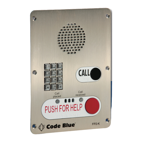
Thank you for choosing Centry®for your Code Blue application. Centry®is a compact Help Point®
featuring a hands-free speakerphone, IP color camera and station identication light. It has full
duplex capabilities and runs on PoE or 12V DC power. It is mounted with vandal resistant screws for
security.
2 Button Flush Mount 1 Button Surface Mount1 Button Flush Mount 2 Button Surface Mount
Other features include:
• Powered by EmerComm®
• Ring-lit piezoelectric buttons
Call Privacy Laws
Some states require all parties to be aware that they are being recorded. Code Blue phones offer
the ability to play a message stating that the caller is being recorded and giving the caller the option
to continue or end the recorded call.

Code Blue •259 Hedcor Street •Holland, MI 49423 USA •800.205.7186 •www.codeblue.com GU-162-Epage 5 of 56
Centry®
Administrator Guide
3 Getting Started
This guide contains information and a general overview for Centry, including applications, installation
and wiring.
Centry Series Features
• 1- and 2-button congurations
• SIP protocol support
• Station Beacon Light for visual identication
• 3 Ethernet ports
• 3 auxiliary N.O. input contact closures
• 3 auxiliary N.O. output contact closures
• NEMA 3S Compliant
• UL 60950-22 Compliant
• Contemporary faceplate design, with multiple ADA compliant lettering choices with Braille
Type 1 Button Flush 2 Button Flush 1 Button Surface 2 Button Surface
Width (in) 4.5 4.5 4.75 4.75
Height (in) 10 10 10.25 4.5
Depth (in) 3.125 3.125 2.875 2.875
Weight (lbs) 4444
Op. Temp. (°F) -40F - +158F
(-40°C - +70°C)
-40F - +158F
(-40°C - +70°C)
-40F - +158F
(-40°C - +70°C)
-40F - +158F
(-40°C - +70°C)
Centry Faceplate Tools
1. T10 pin Torx driver.
Part Part Number
Trim Ring 40002
Speaker N/A
Mic Assembly N/A
Light N/A
Curb Mount 41461
Piezoelectric Button N/A
Indoor 24V AC to 12V DC Adapter Cord 41598
Outdoor 24V AC to 12V DC Adapter Cord (rated for -30 to +70 °C) 40525
Centry Mounting Screws (4pk) 40004

Code Blue •259 Hedcor Street •Holland, MI 49423 USA •800.205.7186 •www.codeblue.com GU-162-Epage 6 of 56
Centry®
Administrator Guide
Flush Mount Drawing
FRONT VIEW
SIDE VIEW
BOTTOM VIEW
BACK VIEW
CENTRY
2 BUTTON
CENTRY
1 BUTTON

Code Blue •259 Hedcor Street •Holland, MI 49423 USA •800.205.7186 •www.codeblue.com GU-162-Epage 7 of 56
Centry®
Administrator Guide
Surface Mount Drawing
FRONT VIEW
SIDE VIEW
BOTTOM VIEW
BACK VIEW
CENTRY
2 BUTTON
CENTRY
1 BUTTON

Code Blue •259 Hedcor Street •Holland, MI 49423 USA •800.205.7186 •www.codeblue.com GU-162-Epage 8 of 56
Centry®
Administrator Guide
4 Installation Instructions
Legal Considerations
Video and audio surveillance can be regulated by laws that vary
from country to country. Check the laws in your local region before
using this product for surveillance purposes.
Liability
Every care has been taken in the preparation of this document.
Please inform Code Blue Corporation of any inaccuracies or omis-
sions. Code Blue cannot be held responsible for any technical or
typographical errors and reserves the right to make changes to the
product and manuals without prior notice. Code Blue makes no
warranty of any kind with regard to the material contained within
this document, including, but not limited to, the implied warranties of
merchantability and tness for a particular purpose. Code Blue shall
not be liable or responsible for incidental or consequential damages
in connection with the furnishing, performance or use of this mate-
rial. This product is only to be used for its intended purpose.
Intellectual Property Rights
Code Blue Corporation has intellectual property rights relating to
technology embodied in the product described in this document.
This product contains open source code that also contains ad-
ditional open source libraries.
Equipment Modifications
This equipment must be installed and used in strict accordance with
the instructions given in the user documentation. This equipment
contains no user-serviceable components. Unauthorized equipment
changes or modications will invalidate all applicable regulatory
certications and approvals.
Trademark Acknowledgments
Code Blue and Centry products are registered trademarks or trade-
mark applications of Code Blue Corporation in various jurisdictions.
All other company names and products are trademarks or registered
trademarks of their respective companies.
Regulatory Information
Electromagnetic Compatibility (EMC)
This equipment has been designed and tested to fulll applicable
standards for:
• Radio frequency emission when installed according to the
instructions and used in the intended environment.
• Immunity to electrical and electromagnetic phenomenon
when installed according to the instructions and used in its
intended environment.
USA
This equipment has been tested using a shielded network cable
(STP) and found to comply with the limits for a Class A digital
device, pursuant to part 15 of the FCC Rules. These limits are
designed to provide reasonable protection against harmful interfer-
ence when the equipment is operated in a commercial environment.
This equipment generates, uses and can radiate radio frequency
energy and, if not installed and used in accordance with the instruc-
tion manual, may cause harmful interference to radio communica-
tions. Operation of this equipment in a residential area is likely to
cause harmful interference in which case the user will be required
to correct the interference at their own expense. The product shall
be connected using a shielded network cable (STP) that is properly
grounded.
Canada
This digital apparatus complies with CAN ICES-3 (Class A). The
product shall be connected using a shielded network cable (STP)
that is properly grounded. Cet appareil numérique est conforme à la
norme NMB ICES-3 (classe A). Le produit doit être connecté à l’aide
d’un câble réseau blindé (STP) qui est correctement mis à la terre.
Safety
This product complies with 62638-1/UL 60950-1 and 62638-1/UL
60950-22, Safety of Information Technology Equipment. The product
shall be grounded either through a shielded network cable (STP) or
other appropriate method. The power supply used with this product
shall fulll the requirements for Safety Extra Low Voltage (SELV)
and Limited Power Source (LPS) according to IEC/EN/UL 60950-1.
This unit complies with IP54/NEMA 3 and IEC 61969-3 Class 1
specications.
Warranty
Code Blue Corporation provides a limited warranty on this product.
Refer to your sales agreement to establish the terms. In addition,
Code Blue’s standard warranty language, as well as information
regarding support for this product while under warranty, is available
at www.codeblue.com/support/downloads.
In Case of Breakdown
In case of system breakdown, discontinue use and contact Tech
In Case of Abnormal Operation
If the unit emits smoke or an unusual smell, if water or other foreign
material enters the enclosure, or if you drop the unit or damage the
enclosure, power off the unit immediately and contact:
(800) 205-7186, option 2.
Disposal and Recycling
When this product has reached the end of its useful life, dispose
of it according to local laws and regulations. For information about
your nearest designated collection point, contact your local authority
responsible for waste disposal. In accordance with local legislation,
penalties may be applicable for incorrect disposal of this waste.
This guide should contain all the information needed for your
application. If any further information is needed, please contact
Support
Should you require any technical assistance, please contact Code
Blue. Visit codeblue.com to:
• Download user documentation and software.
• Find answers to resolved problems in the FAQ database.
• Report problems to Code Blue Technical Support via email
Code Blue •259 Hedcor Street •Holland, MI 49423 USA •800.205.7186 •www.codeblue.com GU-162-Epage 9 of 56
Centry®
Administrator Guide
Safety Information
Hazard Levels
DANGER
Indicates a hazardous situation which, if not avoided, will result in death or serious injury.
WARNING
Indicates a hazardous situation which, if not avoided, could result in death or serious injury.
CAUTION
Indicates a hazardous situation which, if not avoided, could result in minor or moderate injury.
NOTICE
Indicates a situation which, if not avoided, could result in damage to property. Other message levels
Important indicates signicant information that is essential for the product to function correctly. Note:
Indicates useful information that helps in getting the most out of the product.
Other Message Levels
Important
Indicates signicant information that is essential for the product to function correctly.
Note
Indicates useful information that helps get the most out of the product.
Safety Instructions
WARNING
• Code Blue products shall be installed by trained professionals.
NOTICE
• Code Blue products shall be used in compliance with local laws and regulations.
• Store the Code Blue product in a dry and ventilated environment.
• Do not install the product on unstable brackets, surfaces or walls.
• Use only applicable tools when installing Code Blue products.
• Do not use chemicals, caustic agents, or aerosol cleaners other than those tested and recom-
mended by Code Blue.
• Use only accessories that comply with technical specications of the product. These can be
provided by Code Blue or a third party.
• Use only spare parts provided by or recommended by Code Blue.
• Do not attempt to repair the product by yourself. Contact Code Blue or your Code Blue re-
seller for service.
Transportation
NOTICE
• When transporting a Code Blue product, use the original packaging or equivalent to prevent
damage to the product.

Code Blue •259 Hedcor Street •Holland, MI 49423 USA •800.205.7186 •www.codeblue.com GU-162-Epage 10 of 56
Centry®
Administrator Guide
What’s Included
Quantity Part Description
1 Centry®Help Point®
1 Enclosure (Surface or Flush)
4 Security Screws
2 Knockout Covers
1 Faceplate / Circuit board with Integrated IP Color Camera and Beacon Light
Centry faceplate tools needed for installation:
1. Drill and screws to mount unit to wall.
2. T10 pin Torx driver.
Basic Flush Mount Installation Instructions:
1. The ush mount enclosure will come with no mounting holes. It can be mounted from the
sides, top or bottom. Once your mounting needs have been determined, drill the holes
needed for your specic installation requirements into the ush mount back box.
2. Mark the mounting holes onto the mounting surface. In order to comply with the Ameri-
cans with Disabilities Act (ADA) of 1990, the speakerphone button(s) should be positioned
between 34 and 48 inches from grade level. (Consult an ADA specialist in your area to verify
local and federal guidelines.)
3. Connect earth ground to the provided copper grounding lug using a minimum 14 gauge
conductor.
4. Connect electrical and communications wiring using the wiring diagram below.
5. Follow all federal and local codes that apply.
6. Attach faceplate to enclosure using four security screws.
Basic Surface Mount Installation Instructions:
1. Open shipping box and remove Centry unit.
2. Remove four security screws with T10 Torx driver.
3. Separate Centry from enclosure and set aside carefully.
4. Mark the mounting holes onto the mounting surface. In order to comply with the Ameri-
cans with Disabilities Act (ADA) of 1990, the speakerphone button(s) should be positioned
between 34 and 48 inches from grade level. (Consult an ADA specialist in your area to verify
local and federal guidelines.)
5. Drill all marked holes.
6. Secure the housing to the wall – If you are securing to drywall, utilize drywall screws and
anchors. If you are securing to metal, utilize sheet metal screws. If you are securing to brick,
use Tapcon screws. Fasten all screws securely.
Important: Ensure that conduit is aligned with wiring.

Code Blue •259 Hedcor Street •Holland, MI 49423 USA •800.205.7186 •www.codeblue.com GU-162-Epage 11 of 56
Centry®
Administrator Guide
7. Connect earth ground to the provided copper grounding lug using a minimum 14 gauge
conductor.
8. Connect electrical and communications wiring using the wiring diagram below.
9. Follow all federal and local codes that apply.
10. Attach faceplate to enclosure using four security screws.
1. Find both the CAT cable location and stud/mounting
structure in the wall. Mark it clearly.
2. Remove the four screws from the back box of the Centry
faceplate.
3. At the mounting location, using the back box as a guide on
the wall, mark the rough opening size.
4. Cut the required opening using available hand tools or an
electric saw.
5. Drill the mounting holes needed into your back box and
mount it to the structure.
6. Pull the CAT cable through the conduit hole in the back box.
7. Connect the CAT cable to the Ethernet port on the Centry
PCB.
8. Re-attach the Centry faceplate to its back box.
9. Screw the four faceplate screws back in place.
Vertical
Orientation

Code Blue •259 Hedcor Street •Holland, MI 49423 USA •800.205.7186 •www.codeblue.com GU-162-Epage 12 of 56
Centry®
Administrator Guide
5 Wiring Diagram
1 - Cat 5e - Connect to Switch (100 Mb)
2 - Cat 5e - Connect to Peripheral (100 Mb)
3 - Cat 5e - Connect to Peripheral (100 Mb)
4 - Optional 12V battery
5 - 12V DC power
6 - Aux outputs (3)
• The auxiliary outputs are Normally Open and can be triggered in your action script to
close. Duration is dened in your action script.
7 - Aux inputs (3)
• The auxiliary inputs are Normally Open and are triggered by voltage. The voltage range is
9 to 32V AC or DC with current protection of 1.25 Amps.
8 - Factory Reset Switch
• With power connected to Centry, hold down this reset switch for 12 seconds and then
release. The unit will reboot. All settings will be lost.
Code Blue Corp®
ed-20011-a_Centry_Board_Connections (2).vsd_revised.vsd
Wiring map concept
SIZE FSCM NO DWG NO REV
SCALE 1 : 1 Mike Rose SHEET 1 OF 1
Engineering Dept
Code Blue
PAS Control
Cable
PoE
WAN LAN 1
PASAudio
Batt Aux
Pwr
Main
Pwr Outputs Inputs
Reset
LAN 2
- + - + 1 1 2 2 3 3 1 1 2 2 3 3
12v DC
? buzzer
Momentary
Trigger
To Pwr
Code Blue PAS Amp
Control Plug
RJ-11Audio
Flat Cable to Amp
WAN
PoE enabled
Ethernet
LAN port 1 LAN port 2
Layers have been used on this page.
Do not add anything without checking the layer list
USER’s Connections
123
4
6
9
8
7
5
8
12 V DC (max 400mA)
Finger Safe header
CAUTION
PCB is sensitive to
static discharge
NOTICE
12V SLA 2 Ah battery
source (max 400mA)
CAUTION
Power over Ethernet
802.3 af/at 37-57V DC
(max 350mA)
DANGER

Code Blue •259 Hedcor Street •Holland, MI 49423 USA •800.205.7186 •www.codeblue.com GU-162-Epage 13 of 56
Centry®
Administrator Guide
6 Flush Mount Mounting Schematics
0
9.466
0
.317
3.817
4.134
1.164
1.164
B
B
1.083
3.051
.866
2.884

Code Blue •259 Hedcor Street •Holland, MI 49423 USA •800.205.7186 •www.codeblue.com GU-162-Epage 14 of 56
Centry®
Administrator Guide
7 Surface Mount Mounting Schematics
.875
.250 TYP
3.360
1.360
3.360
2.360
1.382
3.382
8.862
2.131
1.360
1.083
3.051
.866
2.884

Code Blue •259 Hedcor Street •Holland, MI 49423 USA •800.205.7186 •www.codeblue.com GU-162-Epage 15 of 56
Centry®
Administrator Guide
8 Curb Mount Installation Instructions
Overview
These instructions are intended to assist in installing the curb mount on most concrete foundations,
curbs or sidewalks.
Pre-Installation
Electrical Preparation
Depending on the model of unit being installed, the line communications and power wires will need
to be run through the curb mount and at least 10 inches of wire exposed out of each opening.
Installation Procedures
Curb Mount should be mounted on concrete bases with a depth of 4-5 inches, using the correct
mounting bolts for your application.
Mounting Holes
In order to comply with the Americans with Disabilities Act (ADA), the speakerphone button(s)
should be positioned between 34 and 48 inches from grade level (Consult an ADA specialist in your
area to verify local and federal guidelines).
Secure the housing to the Curb Mount
Four bolts with four locknuts, four rubber washers and eight steel washers are provided to securely
fasten the housing to the curb mount. Connect communications and power wiring where applicable.
Follow all federal and local codes that apply.
Recommended Base Mounting Bolt
This bolt is best suited for structural connections, i.e., column anchorage.
The bolt (SD6) is made from 316 stainless steel, which provides corrosion resistance.

Code Blue •259 Hedcor Street •Holland, MI 49423 USA •800.205.7186 •www.codeblue.com GU-162-Epage 16 of 56
Centry®
Administrator Guide
Curb Mount Option
Specifications
Height: 43 in (109.22 cm)
Width: 7 in (17.78 cm)
Construction: Schedule 40 steel tubing
Mounting Base: 7 in diameter (17.78 cm)
Finish: Black (Custom colors available)
CPS-133-I
© 2016 Code Blue Corporation page 2 of 2
Note: Specifications subject to change without notice or obligation on the part of Code Blue Corporation.
Specifications
• Height: 43” (109.22 cm)
• Width: 7” (17.78 cm)
• Construction: Schedule 40 steel tubing
• Mounting Base: 7” diameter (17.78 cm)
• Finish: Black
○Custom colors available
Available for the:
• IP2500
• Centry
Mounting Schematics
39.50
7.00
7.00
43.00
7.00
10.50
5.75
1.50
7.00
7.00
2.13
3.63
4.25
1.50
#10-24 x(4)
1.38
3.50
3.50
MOUNTING PLATE DETAIL
SCALE 1:3
B
STEEL WELDMENT
C
SIDE VIEW
FORNT VIEW
BOTTOM VIEW
REVISIONS
REV.
DATE
BY
CH/AP
B
REDRAWN
7/24/2014
DM
C
REDRAWN, CHANGED TAP SIZE TO #10-24
10/16/2015
KRH
ITEM NO.
PART NUMBER
DESCRIPTION
QTY.
1
7in DIA. BASE
1/4" x 7" DIA. PLATE
1
2
7in SQ PLATE
1/4" x 7" x 7" SQUARE PLATE
1
3
SCH 40 PIPE
1 1/2" Sch 40 PIPE PRE BEND LENGTH 48"
1
A A
B B
4
4
3
3
2
2
1
1
Technical Features
IP2500/Centry
39.50
7.00
7.00
43.00
7.00
10.50
5.75
1.50
7.00
7.00
2.13
3.63
4.25
1.50
#10-24 x(4)
1.38
3.50
3.50
MOUNTING PLATE DETAIL
SCALE 1:3
B
STEEL WELDMENT
C
SIDE VIEW
FORNT VIEW
BOTTOM VIEW
REVISIONS
REV.
DATE
BY
CH/AP
B
REDRAWN
7/24/2014
DM
C
REDRAWN, CHANGED TAP SIZE TO #10-24
10/16/2015
KRH
ITEM NO.
PART NUMBER
DESCRIPTION
QTY.
1
7in DIA. BASE
1/4" x 7" DIA. PLATE
1
2
7in SQ PLATE
1/4" x 7" x 7" SQUARE PLATE
1
3
SCH 40 PIPE
1 1/2" Sch 40 PIPE PRE BEND LENGTH 48"
1
A A
B B
4
4
3
3
2
2
1
1

Code Blue •259 Hedcor Street •Holland, MI 49423 USA •800.205.7186 •www.codeblue.com GU-162-Epage 17 of 56
Centry®
Administrator Guide
Dual Curb Mount Option
Specifications
Height: 77.51 in (196.88 cm)
Width: 4.72 in (11.99 cm)
Construction: Schedule 40 steel tubing
Mounting Base: 7 in diameter (17.78 cm)
Finish: Black: (Custom colors available)
CPS-133-I
© 2016 Code Blue Corporation page 1 of 2
CURB MOUNT OPTION
Technical Features (See page 2 for more options.)
Specifications
• Single Mount Height: 50” (127 cm)
• Dual Mount Height: 80.02” (191.77 cm)
• Width: 6.75” (17.145 cm)
• Construction: Schedule 40 steel tubing
• Mounting Base: 7” diameter (17.78 cm)
• Finish: Black
○Custom colors available
Available for the:
• CB 4-s
• CB 4-r
• CB 6-s
Product Description
The free-standing Curb Mount options are ideal for drive-up or walk-up applications
using Code Blue’s industry leading call boxes and emergency speakerphones.
45.50
9.00
6.75
50.00
10.50
7.00
1.50
5.75
0.44 (TYP.)
0.50
5.750.50
0.50
8.00
4.50
3.38 0.44
(TYP.)
MOUNTING PLATE DETAIL
SCALE 1:3
FRONT VIEW
SIDE VIEW
BOTTOM VIEW
Mounting Schematics
45.50
9.00
6.75
50.00
10.50
7.00
1.50
5.75
0.44 (TYP.)
0.50
5.750.50
0.50
8.00
4.50
3.38 0.44
(TYP.)
MOUNTING PLATE DETAIL
SCALE 1:3
FRONT VIEW
SIDE VIEW
BOTTOM VIEW
45.50
9.00
6.75
50.00
10.50
7.00
1.50
5.75
0.44 (TYP.)
0.50
5.750.50
0.50
8.00
4.50
3.38 0.44
(TYP.)
MOUNTING PLATE DETAIL
SCALE 1:3
FRONT VIEW
SIDE VIEW
BOTTOM VIEW
CB 4-s/4-r/4-u/6-s
Single Mount
Dual Mount
45.50
9.00
6.75
50.00
10.50
7.00
1.50
5.75
0.44 (TYP.)
0.50
5.750.50
0.50
8.00
4.50
3.38 0.44
(TYP.)
MOUNTING PLATE DETAIL
SCALE 1:3
FRONT VIEW
SIDE VIEW
BOTTOM VIEW
45.75
75.52
9.00
6.75
80.02
45.75
75.52
9.00
6.75
80.02

Code Blue •259 Hedcor Street •Holland, MI 49423 USA •800.205.7186 •www.codeblue.com GU-162-Epage 18 of 56
Centry®
Administrator Guide
9 Setting up your Centry® Help Point®
If no DHCP server is available, download and install TFTPD32 from tftpd32.jounin.net to turn a com-
puter into a DHCP server.
Determine the IP Address
Centry is DHCP out of the box. Once you’re able to browse into the device, you can switch to a
static IP if desired. Please note it does not have a default static IP address.
Connect Centry to your DHCP Network. The button LEDs will turn red during the boot process and
blue when booted up. Centry will acquire its network settings from the DHCP server on the network.
If the network is not running DHCP, then you will need a router to plug the Centry into, as well as
your PC so you can get into the device.
If you do not have network scanner software, you can download many free ones. “Advanced IP
Scanner” is one example. Run a scan of the subnet the Centry device is plugged into, and your PC
if plugged into the same network.
You can nd the IP address for your Centry speakerphone by matching its MAC address.
You can then browse to the IP address of the device. The recommended web browser is Google
Chrome. You may experience eratic behavior with other browsers.
Default login information is:
Username: admin
Password: admin

Code Blue •259 Hedcor Street •Holland, MI 49423 USA •800.205.7186 •www.codeblue.com GU-162-Epage 19 of 56
Centry®
Administrator Guide
Network - General Settings
Once logged into the device, you can change the Network Settings in General Settings under
Network if you want to switch over to a static IP address.
Generally, you can leave the Host and Domain elds empty.
SSH Port 22 is enabled by default. You can change the Port and disable it, if desired.
If limiting Network Ports, then the ports to have open are:
• tcp 22 SSH Secure Shell Protocol (Congurable)
• tcp 53 DNS Domain Name Service over TCP
• udp 53 DNS Domain Name Service over UDP
• tcp 80 HTTP Hyper Text Transfer Protocol
• tcp 161 SNMP Simple Network Management Protocol
• tcp 162 SNMP Trap Simple Network Management Protocol Trap
• tcp 443 SSL Secure Socket Layer (Deprecated)
• tcp 554 RTSP Real Time Streaming Protocol
• udp 554 RTSP Real Time Streaming Protocol
• udp 5060 SIP Session Initiation Protocol
• tcp 5062 SIP Session Initiated Protocol
• rtp 16384-32767 Real Time Transport (Congurable)

Code Blue •259 Hedcor Street •Holland, MI 49423 USA •800.205.7186 •www.codeblue.com GU-162-Epage 20 of 56
Centry®
Administrator Guide
Accounts
Add Account
These settings are usually provided by IP PBX, SIP server or SIP gateway personnel.
Account Name: Free form eld to identify the account.
Username/Number: Phone number or extension for the Centry device.
Speaker Volume: You can set the speaker volume gain here in the GUI, as well as from a touch-
tone phone using in-call commands. This becomes the default volume level.
Mic Volume: You can set the mic volume gain here in the GUI, as well as from a touch-tone phone
using in-call commands. This becomes the default volume level.
SIP Server Settings
Server IP Address: You can use the domain name or IP address of your IP PBX, SIP Gateway,
SBC or whatever you register SIP devices to.
Password: This is the shared SIP secret password that the phone and your SIP registration server
share.
Server Port: 0 for auto detect. Commonly may be 5060. If necessary, you may have to specify a
Table of contents
Other Code Blue Telephone manuals

Code Blue
Code Blue IA4100 Service manual

Code Blue
Code Blue IP5000 Quick start guide

Code Blue
Code Blue IP2501-s Service manual

Code Blue
Code Blue IP5000 User manual

Code Blue
Code Blue LS2000 Manual

Code Blue
Code Blue IA3100 Service manual

Code Blue
Code Blue IP1500 User manual

Code Blue
Code Blue CB RT Service manual

Code Blue
Code Blue IP5000 2.0 Series Service manual

Code Blue
Code Blue CB 2 Series Service manual