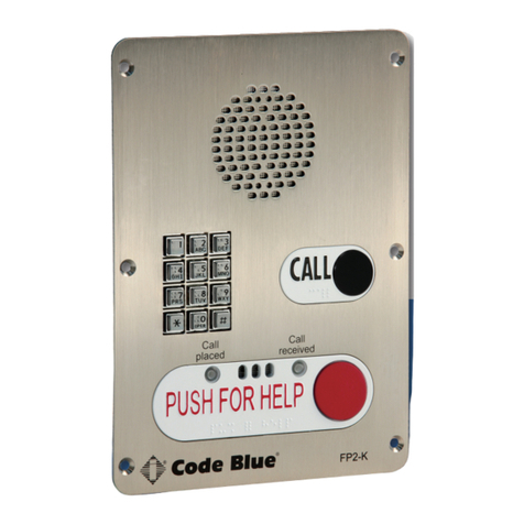
Code Blue IP2501-s Service manual

800.205.7186 •www.codeblue.com
IP1500 and
IP2500 Series
Speakerphones
Administrator Guide
Installation | Configuration | Support | Maintenance | Use

Code Blue •259 Hedcor Street •Holland, MI 49423 USA •800.205.7186 •www.codeblue.com GU-137-Hpage 2 of 67
IP1500 and IP2500 Series
Administrator Guide
Table of Contents
Section Page
2 Introduction....................................................................................3
3 Getting Started...............................................................................4
3.1 What’s included with the IP1500 and IP1501...................... 5
3.2 What’s included with the IP2500 and IP2501.......................6
4 Connectors, Ports and Switch List..............................................7
4.1 IP1500/2500 Printed Circuit Board Layout...........................7
4.2 Wiring Diagram - IP1500 and IP1501..................................8
4.3 Wiring Diagram - IP2500 and IP2501..................................9
5 Installation....................................................................................10
5.1 Surface Mount IP1500.......................................................10
5.2 Flush Mount IP1501...........................................................11
5.3 Surface Mount IP2500.......................................................13
5.4 Flush Mount IP2501...........................................................14
6 Provisioning the Phone...............................................................18
6.1 Determine the IP Address..................................................18
6.2NetworkConguration.......................................................21
6.3ConguringVoIPSettings..................................................23
6.4ConguringtheSystemSettings........................................28
6.5ConguringSystemOptionsandScripts............................32
7 CLI (Command Line Interface)....................................................45
8 In-Call Commands.......................................................................46
9 Factory Reset...............................................................................47
10 Compatibility................................................................................49
11 Conguring for Cisco Unied Communications Manager 9....50
12 Avaya IP Ofce Integration Guide.............................................. 54
13 Using the IP1500 and IP2500 Speakerphones .........................61
14 Troubleshooting the IP1500 and IP2500 Speakerphone..........62
15 Technical Specications.............................................................63
16 Regulatory....................................................................................65
14.1 ETL Required Labeling......................................................65
17 Warranty.......................................................................................66
18 Technical Services and Support................................................67

Code Blue •259 Hedcor Street •Holland, MI 49423 USA •800.205.7186 •www.codeblue.com GU-137-Hpage 3 of 67
IP1500 and IP2500 Series
Administrator Guide
2 Introduction
ThankyouforchoosingtheCodeBlueIP1500andIP2500SeriesfullduplexVoIPspeakerphone(s),
intercomandpagingdevice(s)forindoorandoutdoorapplications.Thesespeakerphonesarebuilt
tomeetthelatestregulations,withstandtheharshestelementsandbeproactivesolutionsforwhen
youneedthemmost.Thisguideprovidesbasicandadvancedcongurationinformationforobtain-
ingthebestperformancewiththeIP1500andIP2500Seriesspeakerphone(s).
Thesedevicesarelistedasnon-emergencysignalingandarenon-monitoredindoor/outdoorcom-
munication units.
IP1500 Surface Mount
IP1501 Flush Mount
IP2500-s Surface Mount
IP2501-d Flush MountIP2501-s Flush Mount
IP2500-d Surface Mount

Code Blue •259 Hedcor Street •Holland, MI 49423 USA •800.205.7186 •www.codeblue.com GU-137-Hpage 4 of 67
IP1500 and IP2500 Series
Administrator Guide
3 Getting Started
ThischapterprovidesinformationforobtainingthebestperformancewiththeIP1500andIP2500
Seriesspeakerphone.Itisstronglyrecommendedthattheentireguideisreadbeforeconguring
yourIP1500andIP2500Seriesspeakerphonetoensureyougetmaximumperformance.
Throughout this guide you will see the following two references:
Calling party: Thisisthepersonactivatingthespeakerphonebypressingabutton.
Called party:Thisisthepersonreceivingthecallfromthespeakerphone;typicallyaguard,911
operator,dispatchofcer,etc.
Thesespeakerphonesprovidespowerful,yetexibleIPcommunication,anddeliverexcellentvoice
qualityforyourspeakerphone,intercomandpagingsolution.

Code Blue •259 Hedcor Street •Holland, MI 49423 USA •800.205.7186 •www.codeblue.com GU-137-Hpage 5 of 67
IP1500 and IP2500 Series
Administrator Guide
3.1 What’s included with the IP1500 and IP1501 Series
IP1500 Surface Mount
Quantity Part No. Description
1SurfaceMountBox Included
1 Mounting Bracket Included
4 No. 4 Security Screws Included
4 No. 4 Screws Not Included
1FourSquareBox Not Included
1InstallationandSetUpGuide Included
AStandardDrilledSpannerInsertBitisrequiredtotheaccessunit–Not Included
IP1501 Flush Mount
Quantity Part No. Description
1Faceplate Included
1WeatherproofBackBox Included
4 No. 4 Security Screws Included
1 No. 4 Screws Included
AStandardTamper-ResistantInsertBitisrequiredtoaccessunit–Not Included

Code Blue •259 Hedcor Street •Holland, MI 49423 USA •800.205.7186 •www.codeblue.com GU-137-Hpage 6 of 67
IP1500 and IP2500 Series
Administrator Guide
3.2 What’s included with the IP2500 and IP2501 Series
IP2500-s and IP2500-d Surface Mount
Quantity Part No. Description
1SurfaceMountBox Included
1 Mounting Plate Included
2 Retaining Screws Included
4 No. 8 Screws Included
1 Standard Security Bit Included
1InstallationandSetUpGuide Included
IP2501-s and IP2500-d Flush Mount
Quantity Part No. Description
1FaceplateAssembly Included
1WeatherproofBackBox Included
4 Retaining Screws Included
1 Standard Security Bit Included
1InstallationandSetUpGuide Included
MountinghardwareforBackBox Not Included

Code Blue •259 Hedcor Street •Holland, MI 49423 USA •800.205.7186 •www.codeblue.com GU-137-Hpage 7 of 67
IP1500 and IP2500 Series
Administrator Guide
4 Connectors, Ports and Switch List
TheIP1500andIP2500Serieshasacompactdesignsmallenoughandislightenoughtoensure
aneasyinstallationatanyneworexistinglocation.TheIP1500/2500hasonePoELANport(IEEE
802.310/100EthernetPort)forconnectingtoanetwork.Asingle,normallyopenauxiliaryoutputis
availabletotriggerdoorlocks,lights,gatesoranyothersecuritydevice.
Theinternalcomponentsconsistofamicrophoneconnector,aspeakerconnector,onePoELAN
port,abuttonconnector(s),onenormallyopenauxiliaryoutputandPCBmountinghardware.
4.1 IP1500 and IP2500 Series Printed Circuit Board Layout
LED Button Connector
AuxiliaryOutputN.O.
PoE LAN Port
SpeakerConnector
MicrophoneConnector
The IP1500 and IP1501 Series is solely
poweredbyPoE,802.3atandafClass0
uponinitialization.

Code Blue •259 Hedcor Street •Holland, MI 49423 USA •800.205.7186 •www.codeblue.com GU-137-Hpage 8 of 67
IP1500 and IP2500 Series
Administrator Guide
4.2 Wiring Diagram IP1500 and IP1501 Series
TheIP1500andIP1501SerieshasonePoELANportfornetworkconnectivityandonenormally
openauxiliaryoutputrelayfortriggeringdevicessuchasaLEDbeacon/strobe,camerapresetacti-
vationinputs,gatecontrolorthirdpartycontrollers.Therelaycanbeprogrammedtoholdtherelay
closedforthedurationofthecall,foraspecictimeperiodortoggledforaspecictimeperiodupon
theoperator’srequest.

Code Blue •259 Hedcor Street •Holland, MI 49423 USA •800.205.7186 •www.codeblue.com GU-137-Hpage 9 of 67
IP1500 and IP2500 Series
Administrator Guide
4.3 Wiring Diagram IP2500 and IP2501 Series
TheIP2500andIP2501SerieshasonePoELANportfornetworkconnectivityandonenormally
openauxiliaryoutputrelayfortriggeringdevicessuchasaLEDbeacon/strobe,camerapresetacti-
vationinputs,gatecontrolorthirdpartycontrollers.Therelaycanbeprogrammedtoholdtherelay
closedforthedurationofthecall,foraspecictimeperiodortoggledforaspecictimeperiodupon
theoperator’srequest.TheIP2500andIP2501Seriesalsohastheoptionofanadditionalbutton
for non-emergency calls.

Code Blue •259 Hedcor Street •Holland, MI 49423 USA •800.205.7186 •www.codeblue.com GU-137-Hpage 10 of 67
IP1500 and IP2500 Series
Administrator Guide
5 Installation
TheIP1500andIP2500Seriescomesinsurfaceandushmountoptions.Thesurfacemountal-
lowsthemountingbrackettobeinstalledduringroughinandthefaceplatewithelectronicsduring
completion.Thefaceplateontheushmountisveinchessquareandprovidesanoverlaptothe
mountingboxtoeliminateadditionaltrimwork.
5.1 Surface Mount IP1500 Series
IP1500SurfaceMount:4.50”wx4.50”hx2.00”d
BackView
4.56
1.38 1.80
.64
3.28
6X
.15 THRU ALL
.28 X 82°
4.56
Vertical
Orientation
NOTE:Threadsealmustbeappliedtoexternalcasescrews.

Code Blue •259 Hedcor Street •Holland, MI 49423 USA •800.205.7186 •www.codeblue.com GU-137-Hpage 11 of 67
IP1500 and IP2500 Series
Administrator Guide
5.2 Flush Mount IP1501 Series
IP1500FlushMount:4.00”wx5.00”h
5.00
5.00
2.16
.58
1.47
1.72
3/4" Conduit Thread
BottomView
IP1500Faceplate-BacksideGrounding IP1501BaseFaceplate-BacksideGrounding
Groundlugwillbeplacedonastudwithbaremetalononesideandakepnutholdingitinplace.
Thelugusedforthe1500requiresa#6eyelettypelug.

Code Blue •259 Hedcor Street •Holland, MI 49423 USA •800.205.7186 •www.codeblue.com GU-137-Hpage 12 of 67
IP1500 and IP2500 Series
Administrator Guide
Four
• Mounttheweatherproofbackboxtoaninside
wall or onto a surface.
• Connect a minimum of CAT 5e cable to the Eth-
ernetswitchport(PoELAN)forconnectivityto
the network.
• Attachthefaceplatetothebackboxwiththefour
-#6securityscrewsprovided.
• ConnectanyauxiliarydevicetotheN.O.aux
output1
Vertical
Orientation
NOTE:Threadsealmustbeappliedtothefourfaceplatesecurityscrews.

Code Blue •259 Hedcor Street •Holland, MI 49423 USA •800.205.7186 •www.codeblue.com GU-137-Hpage 13 of 67
IP1500 and IP2500 Series
Administrator Guide
5.3 Surface Mount IP2500 Series
IP2500SeriesSurfaceMount:7.25”wx7.25”hx2.00”d
7.41
7.17
3.59
3.70
1.56 4.28
2.09
3.39
.88
KNOCK OUT
1.70 2.00 2.00
1.10
.88
KNOCK OUT
2.03
7.41
7.17
3.59
3.70
1.56 4.28
2.09
3.39
.88
KNOCK OUT
1.70 2.00 2.00
1.10
.88
KNOCK OUT
2.03
BackView
• First,removethetworetainingscrews,onefrom
each side of the case
• Removetherearmountingplatebyslidingit
downward
• Usethemountingplateasyourguideonthe
wall,markthemountingandconduitholes
• Removetherearmountingplateandcreatethe
requiredholes,attachthemountingplatetothe
wall
• Pull CAT 5e cable through the conduit hole in
therearmountingplate
• ConnectCAT5ecabletotheEthernetporton
the PCB
• SlidetheIP2500Seriescasedown,starting
fromthetopoftherearmountingplate
• Replacethetworetainingscrews
BottomView
Vertical
Orientation
NOTE:Bydesign,nomaingasketisneededtosealtheenclosures.Theinstallerisresponsiblefor
sealingallscrewswiththreadseal,aswellasapplyingtheproperconduitforaweather-tightseal.

Code Blue •259 Hedcor Street •Holland, MI 49423 USA •800.205.7186 •www.codeblue.com GU-137-Hpage 14 of 67
IP1500 and IP2500 Series
Administrator Guide
5.4 Flush Mount IP2501 Series
IP2501SeriesFlushMount:9.00”wx9.00”h
9.00
9.00
3.60
4.13
1.75
.88
9.00
9.00
3.60
4.13
1.75
.88
BackView BottomView
IP2500SeriesFaceplate-BacksideGrounding IP2501SeriesBaseFaceplate-BacksideGrounding
Groundlugwillbeplacedonastudwithbaremetalononesideandakepnutholdingitinplace.Thelug
usedforthe2500requiresa#6eyelettypelug.

Code Blue •259 Hedcor Street •Holland, MI 49423 USA •800.205.7186 •www.codeblue.com GU-137-Hpage 15 of 67
IP1500 and IP2500 Series
Administrator Guide
• First,removethefourfaceplatescrewsfromthe
backbox
• Usethebackboxasyourguideonthewall,
marktheroughopeningsize
• Createtherequiredopeningandconduitruns
• Pull CAT 5e cable through the conduit hole in
thebackbox
• ConnectCAT5ecabletotheEthernetporton
the PCB
• Attachfaceplatetobackbox
• Replacethefourfaceplatescrews
Vertical
Orientation

Code Blue •259 Hedcor Street •Holland, MI 49423 USA •800.205.7186 •www.codeblue.com GU-137-Hpage 16 of 67
IP1500 and IP2500 Series
Administrator Guide
Special Warning: High Voltage – Range 37 - 57V DC <12.96 watts (27mA)
Grounding
TheIP2500seriesisUL2017safetyrated.DuetothestandardPoE802.3afpowersuppliedbythe
remote(IEEE802.3afor“at”rated)PoESwitch,theIP2500hasaprotectiveearthingterminalcable
available.Theremustbeanuninterruptiblesafetyearthgroundattachedtothegroundinglanyard
provided.Wheneveritislikelythattheprotectionhasbeenimpaired,disconnecttheEthernetcable
untilthegroundhasbeenrestored.Thisisanon-emergency,non-monitoredproductline.
GroundterminationspointshavebeenmarkedinaccordancewithUL2017standards.Approved
iconshavebeenappliedtoindicationthegroundinglocation.
Ground Wire Connection
Locatethe18ggreengroundwire,whichisterminatedwitharinglugthathasbeensecuredtoa
faceplatestud.Thelooseendofthegreengroundwiremustbesecuredtoanearthgroundnearby.
Iftheenclosurehasmarkedgroundinglocation,andagreengroundingscrewisavailable,please
useitwheneverlocalcodesdictateearthgroundisrequired.Groundterminationlocationscanbe
labelledusingthefollowinggraphicsymbol:
Ground Images sample:
Therearenouser-serviceablepartsinsidetheseproducts.Anyservicing,adjustment,maintenance
orrepairmustbeperformedonlybyservice-trainedpersonnel.Theseproductsdonothaveapower
switch;theyarepoweredonwhentheEthernetPoEcableispluggedin.
ELECTRICAL SAFETY WARNINGS
Thisdeviceissuitableforuseinnon-hazardouslocationsonly.
WARNING:ExplosionHazard–Donotreplacethedeviceunlesspowerhasbeenswitchedoffor
theareaisknowntobenon-hazardous.
WARNING: Donotoperatetheequipmentinthepresenceofammablegassesorfumes.Operating
electricalequipmentinsuchanenvironmentconstitutesadenitesafetyhazard.
WARNING: IftheequipmentisusedinamannernotspeciedbyCodeBlueCorp.,theprotection
providedbytheequipmentmaybeimpaired.
WARNING: Donotperformanyservicesontheunitunlessqualiedtodoso.Donotsubstitute
unauthorizedpartsormakeunauthorizedmodicationstotheunit.
WARNING: Properlygroundtheunitbeforeconnectinganythingelse.Unitsnotproperlygrounded
mayresultinasafetyriskandcouldbehazardousandmayvoidthewarranty.Seethe
groundingtechniquesectionforproperwaystogroundtheunit.
WARNING: Donotoperatetheequipmentinamannernotspeciedbythismanual.
WARNING: Donotworkonequipmentorcablesduringperiodsoflightningactivity.
WARNING: InstallonlyinaccordancewithLocal&NationalCodesofAuthoritiesHaving
Jurisdiction. (Revised2010-11-15)5

Code Blue •259 Hedcor Street •Holland, MI 49423 USA •800.205.7186 •www.codeblue.com GU-137-Hpage 17 of 67
IP1500 and IP2500 Series
Administrator Guide
Shield Patch Cable
Note:Beforeapplyingpowertothegroundedswitch,youmustuseavoltmetertoverifythereis
novoltagedifferencebetweenthepowersupply’snegativeoutputterminalandtheswitchchassis
groundingpoint.Iftheuseofshieldedcablesisrequired,itisgenerallyrecommendedtoonly
connecttheshieldatoneendtopreventgroundloopsandinterferewithlowlevelsignals(i.e.
thermocouples,RTD,etc.).Cat5ecablesmanufacturedtoEIA-568Aor568Bspecicationsare
required for use with switches.
IntheeventallCat5epatchcabledistancesareshort(i.e.allEthernetdevicesarelocatedthesame
localcabinetand/orreferencedtothesameearthground),itispermissibletousefullyshielded
cablesterminatedtochassisgroundatbothendsinsystemsvoidoflowlevelanalogsignals.

Code Blue •259 Hedcor Street •Holland, MI 49423 USA •800.205.7186 •www.codeblue.com GU-137-Hpage 18 of 67
IP1500 and IP2500 Series
Administrator Guide
6 Provisioning the Phone
6.1 Determine the IP Address
AllIP1500andIP2500SeriesspeakerphonesareDHCPbydefault.Aprogrammingvideoisavail-
able at www.codeblue.com/support/how-to-videos.
1. Connectthespeakerphonetoyournetwork.TheLEDwillashmomentarilyandanaudible
beepwillbeheardoutofthespeakertoindicatetheOSisloading.TheIP1500/2500speakerphone
willacquireIPNetworksettingsfromyourDHCPserver.
2. CheckyourDHCPleaserecordsorutilizeanetworkscannersuchasSoftPerfect’sNetwork
ScannertomatchtheMACaddressofthespeakerphonetothecorrectIPaddressinyourlease
tableoroutputofthenetworkscanner.
Lease Table and Network Scanner Example

Code Blue •259 Hedcor Street •Holland, MI 49423 USA •800.205.7186 •www.codeblue.com GU-137-Hpage 19 of 67
IP1500 and IP2500 Series
Administrator Guide
Logging Into The System
1. Log in using a web browser.
A. PlacetheIPAddressofyourspeakerphoneintotheURLaddressbarandpress
ENTER.
B. Dependingonthebrowserbeingused,acerticatewarningmaypopup.Goahead
andapproveinordertoloadupthelogindialogbox.
C. Enterusername“admin”andpassword“admin”andpressENTER.
2. System Status Screen.
A. CurrentsessiontimebeforeAuto-Logoutisexecuted.
B. Clicking Renewwillrestartthetimerto10minutes,effectivelykeepingyoulogged
in.Thisstatehelpspreventothersfromlogginginandtakingoverthesession,
therefore
erasinganyunsavedchangesmade.
C. Clicking LogoutwilllogyououtoftheGUI.
D. Network:DisplayscurrentIPaddress,DNSaddress,DNSTertiaryaddress,Account
1’s current status and Account 2’s current status.

Code Blue •259 Hedcor Street •Holland, MI 49423 USA •800.205.7186 •www.codeblue.com GU-137-Hpage 20 of 67
IP1500 and IP2500 Series
Administrator Guide
LoggingOutOfTheSystem
1. Tologoutofthespeakerphone,simplyclickonLogout under Session(see
farleft-handcolumn).
Thespeakerphonewillalsologyououtautomaticallyafter10minutes.
Youwillbepromptedforconrmation.
2. Click OKtocompletethelogoutprocessorCanceltocontinueconguringyour
speakerphone.
This manual suits for next models
5
Table of contents
Other Code Blue Telephone manuals

Code Blue
Code Blue Centry Series Service manual

Code Blue
Code Blue IP1500 User manual

Code Blue
Code Blue CB 2 Series Service manual

Code Blue
Code Blue LS2000 Manual

Code Blue
Code Blue IP5000 User manual

Code Blue
Code Blue IA3100 Service manual

Code Blue
Code Blue CB RT Service manual

Code Blue
Code Blue IP5000 Quick start guide

Code Blue
Code Blue IP5000 2.0 Series Service manual

Code Blue
Code Blue IA4100 Service manual