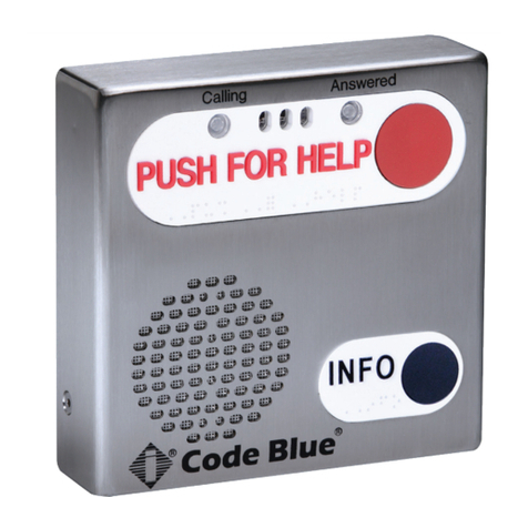
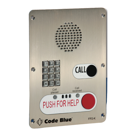
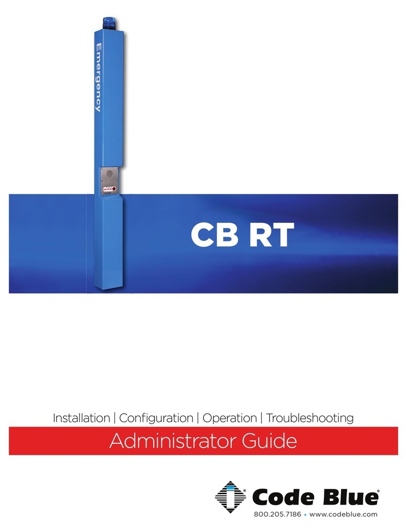
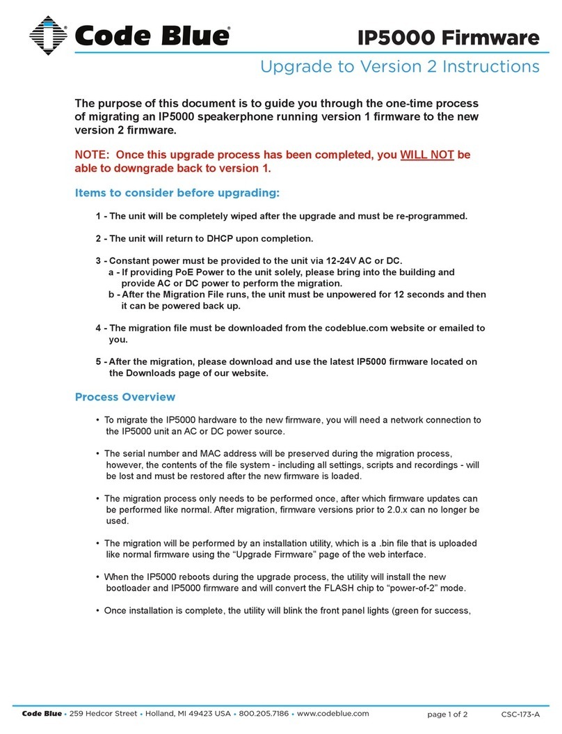
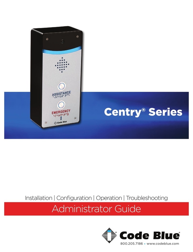
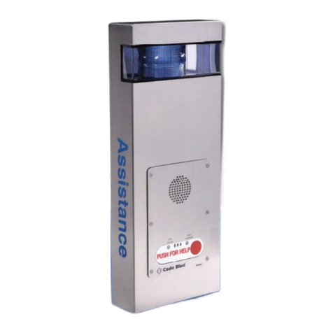
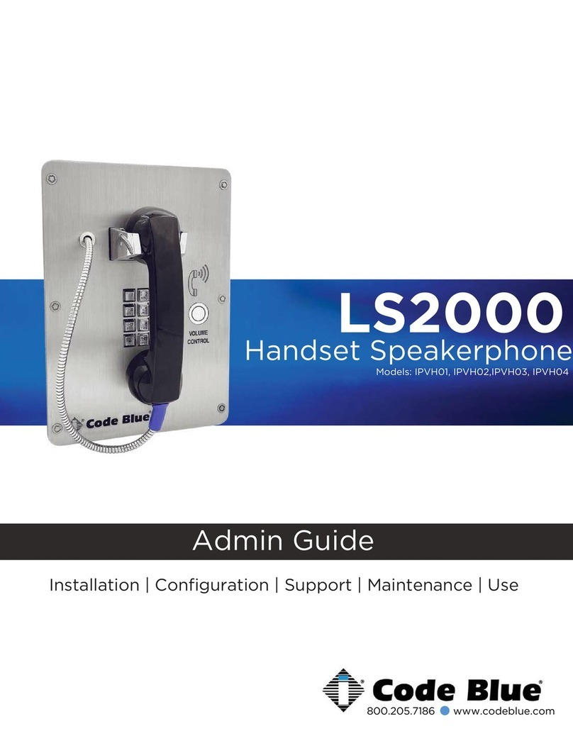
Code Blue IP5000 2.0 Series Service manual

800.205.7186 •www.codeblue.com
IP5000 2.0 Series
VoIP Speakerphone
Administrator Guide
Installation, Configuration, Operation & Troubleshooting

Code Blue •259 Hedcor Street •Holland, MI 49423 USA •800.205.7186 •www.codeblue.com GU-142-Fpage 2 of 61
IP5000 2.0 Series
Administrator Guide
Table of Contents
Section Page
2 Introduction....................................................................................3
3 Getting Started...............................................................................4
4 Connectors, Ports and Switch List .............................................5
5 Wiring Diagram/PoE Wiring Diagram...........................................6
6 Installing the IP5000 Speakerphone.............................................7
6.1 Connecting Power Sources.................................................8
6.2 Connecting Network Services.............................................8
6.3 Connecting Auxiliary Devices..............................................8
6.4 Installation into Code Blue Units.........................................9
7 Optional Flush Mount Enclosure Installation Instructions......10
8 Using the IP5000 Speakerphone................................................ 11
9 Network Setup - Setting a Static IP Address.............................12
10 Provisioning the Phone...............................................................13
10.1 Determine the IP Address.................................................13
10.2 Logging into and out of the System..................................14
10.3NetworkConguration......................................................15
10.4ConguringtheIP5000VoIPSettings...............................18
10.5ConguringtheSystemSettings.......................................23
10.6ConguringSystemOptionsandScripts...........................27
11 Dual Accounts.............................................................................. 42
12 CLI (Command Line Interface)....................................................43
13 In-Call Commands........................................................................44
14 Factory Reset................................................................................45
15 Compatibility.................................................................................47
16 Conguring for Cisco Unied Communications Manager 9....48
17 Avaya IP Ofce Integration Guide.............................................. 52
18 Troubleshooting...........................................................................59
19 Regulatory and Warranty............................................................ 60
20 Technical Services and Support.................................................61

Code Blue •259 Hedcor Street •Holland, MI 49423 USA •800.205.7186 •www.codeblue.com GU-142-Fpage 3 of 61
IP5000 2.0 Series
Administrator Guide
2 Introduction
Thank you for choosing the Code Blue IP5000fullduplexVoIPspeakerphone,intercomand
pagingdeviceforindoorandoutdoorapplications.ThisspeakerphoneispartofourEmergency
Signalinggroupofproductsbuilttomeetthelatestregulations,withstandtheharshestelements
andbeproactivesolutionsforwhenyouneedthemmost.Thisguideprovidesbasicandadvanced
congurationinformationforobtainingthebestperformancewiththeIP5000speakerphone.
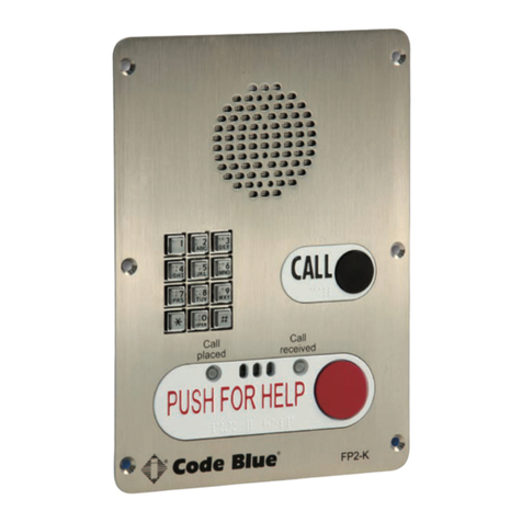
IP5000DualButtonw/KeypadIP5000SingleButton IP5000DualButton

Code Blue •259 Hedcor Street •Holland, MI 49423 USA •800.205.7186 •www.codeblue.com GU-142-Fpage 4 of 61
IP5000 2.0 Series
Administrator Guide
3 Getting Started
ThischapterprovidesinformationforobtainingthebestperformancewiththeIP5000speakerphone.
ItisstronglyrecommendedthattheentireguideisreadbeforeconguringyourIP5000speaker-
phonetoensureyougetmaximumperformance.
Throughout this guide you will see the following two references:
Calling Party:ThisisthepersonactivatingtheIP5000speakerphonebypressingabutton.
Called Party:ThisisthepersonreceivingthecallfromtheIP5000;typicallyaguard,911operator,
dispatchofcer,etc.
TheIP5000speakerphoneprovidespowerful,yetexibleIPemergencycommunication,delivering
excellentvoicequalityforyouremergencyspeakerphone,intercomandpagingsolution.

Code Blue •259 Hedcor Street •Holland, MI 49423 USA •800.205.7186 •www.codeblue.com GU-142-Fpage 5 of 61
IP5000 2.0 Series
Administrator Guide
4 Connectors, Ports and Switch List
TheIP5000speakerphonecomeswithyourchoiceofsinglebutton,dualbuttonordualbuttonwith
keypadfaceplate.Theinternalcomponentsconsistofaspeaker,microphone,PCBandmounting
hardware.

Code Blue •259 Hedcor Street •Holland, MI 49423 USA •800.205.7186 •www.codeblue.com GU-142-Fpage 6 of 61
IP5000 2.0 Series
Administrator Guide
5 Wiring Diagram/PoE Wiring Diagram
ED Image page
2
802.3af / at Switch
LAN 2
LAN 1
WAN
PoEPAS
Control
Aux ports
PAS
Audio
+ -+ -
Power | Battery
S-550
S1000
Ethernet
1
IP5000 Connector Side
Grounding:
Should a ground be needed,
there’s a ground screw on the
enclosure with grounding logo
next to it.
When the splitter is mounted to
the mounting bracket the bracket
becomes the ground to the
chassis of the enclosure,
however local codes may require
a ground wire be attached to the
screw in order to comply.
4
3
Data +PoE
DATA
1b
LED Faceplate Light Bar
12VDC
PoE
CB14591 PoESplitter
2.6
2.1
1.3
1
First, Electrical connection: All 3
Code Blue device’s should to be
connected to the 5 place manifold
Special Note: Notice the power cable is
connected to the Battery / Alternative Power
port of the IP5000. –See Item 1b
2
Second: Manifolds fused red lead
and black wires are secured to
spring cage connector on the
CB14591. SEE DIAGRAM
Third Step: Connect the DATA
cable RJ-45 from the Splitter
“DATA” to the IP5000 WAN PoE
port.
3
4
Fourth Step: Plug in the Ethernet
PoE Cat 5e Cable to Data+PoE
Input jack on the Splitters.
Upon PoE Negotiation with the
PoE switch port, power will be
granted to the Splitter, and the
indicator along with the device
attached will turn on.
Item
InRush
(i)
InRush
Wattage
Norm (i)
802.3af
Wattage
802.3at
Wattage
IP5000 0.22 2.64 0.09 1.08 1.08
FP LED 0.08 0.96 0.04 0.48 0.48
Combo LED 0.3 3.6 0.26 3.12 3.12
Totals 0.6 7.20 0.39 4.68 4.68
CAT5e
< 3ft
in out GRD
3ft
Cat5e
Cust
Cat5e

Code Blue •259 Hedcor Street •Holland, MI 49423 USA •800.205.7186 •www.codeblue.com GU-142-Fpage 7 of 61
IP5000 2.0 Series
Administrator Guide
6 Installing the IP5000 Speakerphone
TheIP5000speakerphoneiscapableofbeingconnectedtoPoE(802.11af&at),12-24VoltsAC
orDCpowersources.Additionally,theIP5000mayalsobeconguredwitha12-VoltDCbattery
backuporalternative12VDCpowersourcesystemwhichmonitorsandreportslowvoltage
conditionforensureduptime.
TheIP5000speakerphonehasthreeEthernetswitchports,onePoELANandtwonon-PoELANS
availableforconnectivitytonetworkservicesandforadditionalnetworkconnectivityforauxiliary
devices,suchasIPcameras,cardreaders,etc.AdditionalLANSarenotVLANcompatible.
TheIP5000speakerphonehastwonormallyopenauxiliaryoutputcontactsforconnectingdevices
suchastheLEDbeacon/strobe,camerapresetactivationinputs,thirdpartycontrollers,etc.There
isalsoonenormallyopenauxiliaryinputcontactclosureforconnectingdevices,suchasdoor
contacts,relays,etc.,whichcanbeprogrammedtoperformanyfunctionofthephone.
TheIP5000speakerphonehasbeendesignedtobemountedinanyCodeBlueenclosure.Custom
faceplatesareavailableformountinginotherproductenclosures.Contactyourlocaldealerfor
additionalinformationandavailabilityofcustomoptions.

Code Blue •259 Hedcor Street •Holland, MI 49423 USA •800.205.7186 •www.codeblue.com GU-142-Fpage 8 of 61
IP5000 2.0 Series
Administrator Guide
6.1 Connecting Power Sources
TheIP5000speakerphoneiscapableofbeingconnectedtoany
powersourcethatprovides12-24VoltsACorDCwithaminimumof
430mAcurrentrating.Optionally,a2.0Ahrbatterycanbeconnected
tothesecondarypowerinputandtheIP5000speakerphonewill
monitorthebatteryforlowvoltageconditions.Whenusedinsolar
orNightCharge®applications,thesystem’sbatteriesvoltageare
monitoredforlowbatterycondition.Itisstronglyrecommendedthat
youdisconnectanypowertotheunitpriortoinstallation.Consult
yourlocalelectricianforproperpowerconnectivitytoyourCode
Blueequipment.
6.2 Connecting Network Services
TheIP5000speakerphonehasthreeEthernetportsthatprovide
bothanupstreamnetworkconnectionpoint,aswellasfunctionas
anEthernetswitch.UpstreamnetworkconnectivityfortheIP5000
canbeconnectedtoanyoftheseports,however,onlytheleftmost
portacceptsPoEpower.Additionaldevices,suchasIPcameras,
cardreaders,etc.canbeconnectedtotheremainingports.
NotethatiftheIP5000isconguredwithaVLANID(seesection
10,“VLANConguration”),onlythespeakerphoneitselfwill
communicateusingVLAN-taggedpackets.Ifadditionaldevices
connectedtotheIP5000’sotherEthernetportsmustcommunicate
onaVLAN,theymusteithersupportVLANtaggingthemselves
(whichwillbepassedthroughtheIP5000’sbuilt-inswitch)orthe
upstreamconnectionmustbeprovidinguntaggedpacketsfromthat
VLAN.
6.3 Connecting Auxiliary Devices
TheIP5000speakerphone’sanalogauxiliaryconnectionsaretwo
normallyopenoutputsandonenormallyopeninput.Typically,any
CodeBlueunitwithanLEDbeacon/strobewillhavethetrigger
connectedtoAuxiliaryOutput1.TheAuxiliaryOutputscanbe
programmedtobeactiveduringacallorbyenteringaspecic
timeperiod.NewtoVersion2,theauxiliaryoutputcouldbe
conguredformomentaryon-demandtimedactivationsviaDTMF
fromthecalledpartyphone.TheAuxiliaryInputcanbeprogrammed
toperformanyscriptenteredintothephone.SeeIP5000User
Guideforfurtherinformationonprogrammingtheauxiliaryoutputs.
IN-147-C
IP5000 v2.0.0
Administrator’s Guide
259HedcorStreetHolland,MI49423800.205.7186www.codeblue.com
1-4 CONNECTING POWER SOURCES
TheIP5000speakerphoneiscapableofbeingconnectedtoanypower
sourcethatprovides12-24VoltsACorDCwithaminimumof430mA
currentrating.Optionally2.0Ahrbatterycanbeconnectedtothe
secondarypowerinputandtheIP5000speakerphonewillmonitorthe
batteryforlowvoltageconditions.Whenusedinsolar or NightCharge®
applications,thesystembatteriesvoltagearemonitoredforlowbattery
condition.Itisstronglyrecommendedthatyoudisconnectanypower
totheunitpriortoinstallation.Consultyourlocalelectricianforproper
powerconnectivitytoyourCodeBlueequipment.
1.5 Connecting Network Services
TheIP5000speakerphonehasthreeEthernetportsthatprovidebothanupstreamnetworkconnectionpointaswell
fasfunctionasanEthernetswitch.Upstreamnetworkconnectivityfor theIP5000canbeconnectedtoanyofthese
ports;however,onlytheleftmostportacceptsPoEpower.AdditionaldevicessuchasIPcameras,cardreaders,etc.
canbeconnectedtotheremainingports.
NotethatiftheIP5000isconfiguredwithaVLANID
(seesection2.5,"VLANConfiguration"),onlythe
speakerphoneitselfwillcommunicateusingVLAN-tagged
packets.IfadditionaldevicesconnectedtotheIP5000's
otherEthernetportsmustcommunicateonaVLAN,they
musteithersupportVLANtaggingthemselves(whichwill
bepassedthroughtheIP5000'sbuilt-inswitch),orthe
upstreamconnectionmustbeprovidinguntaggedpackets
fromthatVLAN.
1-6 CONNECTING AUXILIARY DEVICES
TheIP5000speakerphoneanalogauxiliaryconnectionsare
two(2)normallyopenoutputsandone(1)normallyopeninput.
TypicallyanyCodeBlueunitwithaLEDbeacon/strobewill
havethetriggerconnectedtoAuxiliaryOutput1.TheAuxiliary
Outputscanbeprogrammedtobeactiveduringacallorby
enteringaspecifictimeperiod.Newtoversion2theauxiliary
outputcouldbeconfiguredformomentaryon-demand timed
activationsviaDTMFfromthecalledpartyphone.The
AuxiliaryInputcanbeprogrammedtoperformanyscript
enteredintothephone.Seesections5-8,5-10through5-12
forfurtherinformationonprogrammingtheauxiliaryoutputs.
Page 6
12-24VACorDC
OptionalBattery12VDC2Ahr
Ethernet
PoE
LAN
LAN
LAN
Auxiliary Ports
AuxOutput1
AuxOutput2
AuxOutput1
IN-147-C
IP5000 v2.0.0
Administrator’s Guide
259HedcorStreetHolland,MI49423800.205.7186www.codeblue.com
1-4 CONNECTING POWER SOURCES
TheIP5000speakerphoneiscapableofbeingconnectedtoanypower
sourcethatprovides12-24VoltsACorDCwithaminimumof430mA
currentrating.Optionally2.0Ahrbatterycanbeconnectedtothe
secondarypowerinputandtheIP5000speakerphonewillmonitorthe
batteryforlowvoltageconditions.Whenusedinsolar or NightCharge®
applications,thesystembatteriesvoltagearemonitoredforlowbattery
condition.Itisstronglyrecommendedthatyoudisconnectanypower
totheunitpriortoinstallation.Consultyourlocalelectricianforproper
powerconnectivitytoyourCodeBlueequipment.
1.5 Connecting Network Services
TheIP5000speakerphonehasthreeEthernetportsthatprovidebothanupstreamnetworkconnectionpointaswell
fasfunctionasanEthernetswitch.Upstreamnetworkconnectivityfor theIP5000canbeconnectedtoanyofthese
ports;however,onlytheleftmostportacceptsPoEpower.AdditionaldevicessuchasIPcameras,cardreaders,etc.
canbeconnectedtotheremainingports.
NotethatiftheIP5000isconfiguredwithaVLANID
(seesection2.5,"VLANConfiguration"),onlythe
speakerphoneitselfwillcommunicateusingVLAN-tagged
packets.IfadditionaldevicesconnectedtotheIP5000's
otherEthernetportsmustcommunicateonaVLAN,they
musteithersupportVLANtaggingthemselves(whichwill
bepassedthroughtheIP5000'sbuilt-inswitch),orthe
upstreamconnectionmustbeprovidinguntaggedpackets
fromthatVLAN.
1-6 CONNECTING AUXILIARY DEVICES
TheIP5000speakerphoneanalogauxiliaryconnectionsare
two(2)normallyopenoutputsandone(1)normallyopeninput.
TypicallyanyCodeBlueunitwithaLEDbeacon/strobewill
havethetriggerconnectedtoAuxiliaryOutput1.TheAuxiliary
Outputscanbeprogrammedtobeactiveduringacallorby
enteringaspecifictimeperiod.Newtoversion2theauxiliary
outputcouldbeconfiguredformomentaryon-demand timed
activationsviaDTMFfromthecalledpartyphone.The
AuxiliaryInputcanbeprogrammedtoperformanyscript
enteredintothephone.Seesections5-8,5-10through5-12
forfurtherinformationonprogrammingtheauxiliaryoutputs.
Page 6
12-24VACorDC
OptionalBattery12VDC2Ahr
Ethernet
PoE
LAN
LAN
LAN
Auxiliary Ports
AuxOutput1
AuxOutput2
AuxOutput1

Code Blue •259 Hedcor Street •Holland, MI 49423 USA •800.205.7186 •www.codeblue.com GU-142-Fpage 9 of 61
IP5000 2.0 Series
Administrator Guide
6.4 Installation into Code Blue Units
TheIP5000speakerphoneisdesignedtotintoanyexistingornewCodeBlueunitenclosure.It
isadirectreplacementfortheInterActanalogseries:IA2000,IA3000,IA3100,IA4000andIA4100.
Additionally,CodeBlueofferscustomfaceplatedesignsthatallowtheIP5000tobeplacedin
manydifferentenclosuretypes.CodeBlueprovidessixcustomsecurityscrewsandsecuritybits
witheachCodeBlueunitforattachingtheIP5000speakerphone.Consultyourunitinstallation
instructions for further information.
IN-147-C
IP5000 v2.0.0
Administrator’s Guide
259HedcorStreetHolland,MI49423800.205.7186www.codeblue.com
1-7 INSTALLATION INTO CODE BLUE UNITS
TheIP5000speakerphoneisdesignedtofitintoanyexistingornewCodeBlueunitenclosure.Itisadirect
replacementfortheInterActanalogseries:IA2000,IA3000,IA3100,IA4000andIA4100.Additionally,CodeBlue
offerscustomfaceplatedesignsallowingtheIP5000tobeplacedinmanydifferentenclosuretypes.CodeBlue
providessix(6)custom securityscrewsandsecuritybitwitheachCodeBlueunitforattachingtheIP5000
speakerphone.Consultyourunitinstallationinstructionsforfurtherinformation.
Page7

Code Blue •259 Hedcor Street •Holland, MI 49423 USA •800.205.7186 •www.codeblue.com GU-142-Fpage 10 of 61
IP5000 2.0 Series
Administrator Guide
PRE-INSTALLATION
1.0 Electrical preparation–Theunitmayhavesupplywiresrunfromeither(a)behindtheunit
throughthewall,or(b)belowtheunitbyusinganexternalconduitthroughthebottomoftheunit’s
backplate.Mountingholesintheback,bottomorsideofunittobeadministeredbytheinstaller.
IMPORTANT:Ifwiringiscominginfromthebottomorback,insurethattheconduitis
alignedatthistime.Connectelectricalandcommunicationswiring(seewiringinstructions).Follow
allnationalandlocalcodesthatapply.
1.1 Prepare Wall–FMEenclosuremountingholeinwallshouldexceptthehousingdimensions
belowandmustbesmallerthanthefaceplatedimensionstoensurecleanushmountlook.
INSTALLATION PROCEDURES
1.2 Mark the ush mount mounting hole–InordertocomplywiththeAmericanswithDisabil-
itiesAct(ADA)of1990,thespeakerphonebutton(s)shouldbepositionedbetween34and48inches
fromgradelevel.(ConsultanADAspecialistinyourareatoverifylocalandfederalguidelines.)
1.3 Secure the housing to the wall–TheFlushmountenclosurecanbemountedfromthe
back,bottomorsidebydrillingthemountingholeswhereneededpertheinstallersapplicationwhile
stillkeepingtheunitwithinADAcomplianceheight.(1.2)Mountinghardwaretobesuppliedbyin-
staller.
7 Optional Flush Mount Enclosure Installation Instructions

Code Blue •259 Hedcor Street •Holland, MI 49423 USA •800.205.7186 •www.codeblue.com GU-142-Fpage 11 of 61
IP5000 2.0 Series
Administrator Guide
8 Using the IP5000 Speakerphone
TheIP5000speakerphonecanbeconguredformultipleuses.Themainfunctionistoprovidetwo-
wayvoicecommunications.Pressingbutton#1(Redbutton)PUSH FOR HELP, EMERGENCY or
EMERGENCY/EMERGENCIAwillactivatetheconguredscriptprogrammedforbutton#1.
Button#1activationoverridesanyotheractiontheIP5000isperformingatthetimeofthebutton
press.Forexample,iftheIP5000was:
1. Beingprogrammedatthetime
2. In a monitoring call
3. In the middle of a diagnostic test
4. IntheprocessofaPublicAlertsession
5. Inaninformation(button#2)call.
Button#2,INFO or CALL,aretypicallyutilizedforplacinginformationalcallsorforacquiringdial
toneandutilizingthekeypad,respectively.Anyactionotherthanbutton#1activationisconsidered
Non-Prioritycallingandcommonlyutilizedfordirectorservice,student/employeeparkinglotescort
requests,gateentryrequests,guestservicesandsimilarrequests.
TheIP5000speakerphone’sAuxiliaryOutputsaretypicallyutilizedforactivatingCodeBlue’sLED
Beacon/Strobe,andcanbeusedasanormallyopen(N.O.)drycontactclosure(seeA&Especfor
relayratings)used,forexample,toactivatecentralizedbuilding/securitymanagementequipment.
TheIP5000speakerphone’sAuxiliaryInputisutilizedtomakeanemergencycallorotherfunction
whenactivated.Itcanbeconnectedtoanynormallyopen(N.O.)outputcontactandwillinitialize
theconguredscriptwhenactivated.Typicaluseswouldbedoororgatecontactsforunauthorized
entry,motionsensoractivations,andactivationuponremovalofLifeRingsonpiersorbeaches.The
auxiliaryInputcanbeusedtoresetanoutputleftenabledforlocationidenticationafteracallhas
beenterminatedbythesecuritydesk.
AuxiliaryInputrequiresavoltageof9-32voltsACorDCtodetectaremotedevicescontactclosure.
Incomingcalls:TheIP5000auto-answersanincomingcall,Basedonthesettingsconguredin
General Conguration > Incoming Calls > Answer inImmediatelyorafteranumberofrings.If
theIP5000Public Address > Always Route Incoming Calls to Public Addresswasenabled,
allansweredcallswillnowbebroadcasttothePublicAddressSystem.Inordertocounterthat
automaticanswer/publicaddressenablefeature,thecaller(guard)canexitoutofthatmode
usingthe#2keyonhiskeypad.

Code Blue •259 Hedcor Street •Holland, MI 49423 USA •800.205.7186 •www.codeblue.com GU-142-Fpage 12 of 61
IP5000 2.0 Series
Administrator Guide
9 Network Setup
Determine the IP Address
TheIP5000speakerphoneisDHCPbydefault.
1. ConnecttheIP5000speakerphonetoyournetwork.TheLEDwillashmomentarilyandan
audiblebeepwillbeheardoutofthespeakertoindicatetheOSisloading.TheIP5000
speakerphonewillacquireIPNetworksettingsfromyourDHCPserver.
2. CheckyourDHCPleaserecordsorutilizeanetworkscannersuchasSoftPerfect’sNetwork
ScannertomatchtheMACaddressoftheIP5000speakerphonetothecorrectIPaddress
inyourleasetableoroutputofthenetworkscanner.
Lease Table and Network Scanner Example

Code Blue •259 Hedcor Street •Holland, MI 49423 USA •800.205.7186 •www.codeblue.com GU-142-Fpage 13 of 61
IP5000 2.0 Series
Administrator Guide
10 Provisioning the Phone
10.1 Setting a Static IP Address
OnceyouhaveobtainedtheDHCPaddressoftheIP5000andareloggedintothespeakerphone,
youhavetheoptionofleavingthespeakerphonesetatDHCP(defaultsetting)orsettingastaticIP
address. To set a static IP address:
1. Click on the Network menu item under Network Setup(seefarleft-handcolumn).
2. Under the Generalsection,selectStatic IPastheConnectionType.
3. EnteryourdesiredIPsettingsundertheStaticIPAddressheading.
4. Onceyouhaveenteredallyoursettings,clickonSave Changes.
Note:IfyouhavemovedyourIP5000toanetworkyourPCcannotaccess,youwillhavetocong-
ureyourPCtoaccessthatnetworkbeforecongurationcancontinue.

Code Blue •259 Hedcor Street •Holland, MI 49423 USA •800.205.7186 •www.codeblue.com GU-142-Fpage 14 of 61
IP5000 2.0 Series
Administrator Guide
10.2 Logging into and out of the System
Logging into the System
1. Loginusingawebbrowser.
A. PlacetheIPAddressofyourIP5000intotheURLaddressbarandpressENTER.
B. Dependingonthebrowserbeingused,acerticatewarningmaypopup.Goahead
andapproveinordertoloadthelogindialogbox.
C. Enterusername“admin”andpassword“admin”andpressENTER.
2. System Status Screen.
A. CurrentsessiontimebeforeAuto-Logoutisexecuted.
B. Clicking Renewwillrestartthetimerto10minutes,effectivelykeepingyoulogged
in.Thisstatehelpspreventothersfromlogginginandtakingoverthesession,
therefore erasing any unsaved changes made.
C. Clicking Logout will log you out of the GUI.
D. Network:DisplayscurrentIPaddress,DNSaddress,DNSTertiaryaddress,Account
1’scurrentstatusandAccount2’scurrentstatus.

Code Blue •259 Hedcor Street •Holland, MI 49423 USA •800.205.7186 •www.codeblue.com GU-142-Fpage 15 of 61
IP5000 2.0 Series
Administrator Guide
Logging into the System
1. TologoutoftheIP5000speakerphone,simplyclickonLogout under Session (seefarleft-
handcolumn).
Thespeakerphonewillalsologyououtautomaticallyafter10minutes.
Youwillbepromptedforconrmation.
2. Click OKtocompletethelogoutprocessorCanceltocontinueconguringyourIP5000.

Code Blue •259 Hedcor Street •Holland, MI 49423 USA •800.205.7186 •www.codeblue.com GU-142-Fpage 16 of 61
IP5000 2.0 Series
Administrator Guide
10.3 Network Configuration
OnceyouhaveobtainedtheDHCPaddressoftheIP5000speakerphone,youcanloginandseta
static IP address.
1. Click on the Network menu item under Network Setup(seefarleft-handcolumn).
2. Under General,clickonStatic IP for Connection Type.
3. EnteryourdesiredIPsettingsunderStatic IP Address.
4. Onceyouhaveenteredyoursettings,clickonSave Changes.
NotethatifyouhavemovedyourIP5000toanetworkyourPCcannotaccess,youwillhavetocon-
gureyourPCtoaccessthatnetworkbeforecongurationcancontinue.

Code Blue •259 Hedcor Street •Holland, MI 49423 USA •800.205.7186 •www.codeblue.com GU-142-Fpage 17 of 61
IP5000 2.0 Series
Administrator Guide
VLANConguration
TheIP5000speakerphoneiscapableofperformingIEEE802.1Qframetagginganduserpriority
settings.
1. Click on the Network menu item under Network Setup(seefarleft-handcolumn).
2. Then click on the VLAN EnabledcheckboxintheVLAN section and select your desired
VLANIDandUserPriority.
3. Onceyouhaveenteredyoursettings,clickon Save Changes.
NotethatifyourPCcannotaccessthenewVLAN,youwillhavetocorrectthisproblembefore
continuingconguration,asyouwillloseaccesstotheIP5000.IfyouwishtodisableVLANsupport
andcannotreachtheIP5000onitsconguredVLAN,factory-resettheunittoclearnetworkcongu-
ration.

Code Blue •259 Hedcor Street •Holland, MI 49423 USA •800.205.7186 •www.codeblue.com GU-142-Fpage 18 of 61
IP5000 2.0 Series
Administrator Guide
10.4 Configuring the IP5000 VoIP Settings
TheIP5000speakerphoneisanadvancedVoIPdevicecapableofconnectivitytoVoIPsystemsvia
SIPandIAX2protocols.Built-incodecsprovidemultipleoptionsforcommunicatingwithyourVoIP
systemorCodeBlue’sToolVox®MediaGateway.STUNservercapabilitiesarealsobuilt-inforhelp-
ingtraverserewallswhenconnectingtheunitoutsideofthehostingnetwork.
CONFIGURINGVOIPACCOUNTS
TheIP5000speakerphonecanregistertoVoIPsystemsusingeithertheSIPorIAXprotocols,and
hastheabilitytoregistertotwoseparateVoIPsystemssimultaneouslytoprovideredundancy.
EachoftheIP5000’stwoaccounts,availableunderVoIPSetupasAccount1andAccount2,canbe
conguredaseitherSIPorIAX,subjecttothelimitationthatyoucanonlyhaveoneofthetwoac-
countsconguredasIAX.Ifyouwishtouseonlyoneaccount,setAccount2toDisabled.

Code Blue •259 Hedcor Street •Holland, MI 49423 USA •800.205.7186 •www.codeblue.com GU-142-Fpage 19 of 61
IP5000 2.0 Series
Administrator Guide
ConguringaSIPAccount
EitheroftheIP5000speakerphone’stwoaccountscanbeconguredtoregistertoaVoIPsystem
viaSIP.Congurationisasfollows:
• SettheVoIPProtocoltoSIPandRTP.
• ForDescription,enteranametheIP5000willuseinternallytorefertothisaccount.
• ForUsername/Number,enterthenumberthattheIP5000willuseforSIPaddressing.Thiswill
oftenbetheextensionnumberinaVoIP-basedPBX.
• ForDisplayName,enterthenametheIP5000willsendinSIPtransactions.Thiswilloftenbe
the calling name of the extension.
• ForDomain,enterthedomaintheIP5000willregisterto.
• ForOutboundProxy,enteraSIPproxytheIP5000shouldsendoutboundcallsto.Ifthisisthe
sameasthedomain,youcanleavethiseldblank.
• ForOutboundProxyPort,enteranIPportnumbertheIP5000willsendoutboundcallsto.Typi-
cally,thisshouldbeleftat0.
• ForRegistrationLifetime,enterthetimeinsecondstheIP5000willrequestthatitsregistration
bevalidfor.TheIP5000willautomaticallyre-registerbeforethistimeperiodexpires.
• CheckKeep-AliveifyouwanttheIP5000toperiodicallysendOPTIONSrequeststotheSIP
server,e.g.tokeepaNATconnectionalive.
• CheckSTUNifyouwanttoenableSTUNsupportforthisaccount.
• YoucanadjusttheDTMFThreshholdvalueifyouhavedifcultieswiththeIP5000activatingin-
callcommandswhennoDTMF
ispresent.
• ForUsernameandPassword,
settheusernameandpass-
wordtheIP5000willuseto
authenticate to the domain and
outboundproxy.Notethatthe
username is used for authenti-
cation only and need not match
theUsername/Numbereld
iftheVoIPsystemdoesnot
expectitto.
• VLANuserprioritiescanbead-
justedforSIPandRTPaudio.

Code Blue •259 Hedcor Street •Holland, MI 49423 USA •800.205.7186 •www.codeblue.com GU-142-Fpage 20 of 61
IP5000 2.0 Series
Administrator Guide
ConguringanIAXAccount
EitheroftheIP5000speakerphone’stwoaccountscanbeconguredtoregistertoaVoIPsystem
viaIAX.(Note,however,thatonlyoneofthetwoaccountsmaybeconguredasIAX-theIP5000
doesnotsupporttwosimultaneousIAXaccounts.)
Congurationisasfollows:
• SettheVoIPProtocoltoIAX.
• ForDescription,enteranametheIP5000willuseinternallytorefertothisaccount.
• ForUsername/Number,enterthenumberthattheIP5000willuseforIAXaddressing.Thiswill
oftenbetheextensionnumber
inaVoIP-basedPBX.
• ForDisplayName,enterthe
displaynametheIP5000will
send in IAX transactions. This
willoftenbethecallingnameof
the extension.
• ForDomain,enterthedomain
theIP5000willuseinitsIAX
address.
• ForRegistrar,entertheaddress
oftheIAXservertheIP5000
should register and send
outboundcallsto.Ifthisisthe
sameasthedomain,youcan
leavethiseldblank.
• ForRegistrarPort,enteranIP
portnumbertheIP5000will
registerandsendoutboundcallsto.Typically,thisshouldbeleftat0.
• ForUsernameandPassword,settheusernameandpasswordtheIP5000willusetoauthenti-
catetothedomainandoutboundproxy.Notethattheusernameisusedforauthenticationonly
andneednotmatchtheUsername/NumbereldiftheVoIPsystemdoesnotexpectitto.
• ForRegistrationLifetime,enterthetimeinsecondstheIP5000willrequestthatitsregistration
bevalidfor.TheIP5000willautomaticallyre-registerbeforethistimeperiodexpires.
Table of contents
Other Code Blue Telephone manuals

Code Blue
Code Blue IP5000 User manual

Code Blue
Code Blue IP5000 Quick start guide

Code Blue
Code Blue CB 2 Series Service manual

Code Blue
Code Blue CB RT Service manual

Code Blue
Code Blue IP2501-s Service manual

Code Blue
Code Blue Centry Series Service manual

Code Blue
Code Blue IA3100 Service manual

Code Blue
Code Blue IA4100 Service manual

Code Blue
Code Blue LS2000 Manual

Code Blue
Code Blue IP1500 User manual