manuals.online logo
Brands
  1. Home
  2. •
  3. Brands
  4. •
  5. ENDA
  6. •
  7. Measuring Instrument
  8. •
  9. ENDA ETS1410 User manual

ENDA ETS1410 User manual

Supply voltage 230V AC +%10 -%20, 50/60Hz or 24V AC/DC %10, 50/60Hz±
Power consumption Max. 2VA
2.5mm² screw terminal connection
%0,01
Wiring
Display
Accuracy
EMC
Safety requirements EN 61326-1: 1997, A1: 1998, A2: 2001 (Performance criterion B is satisfied for EMC tests.)
EN 61010-1: 2001 (pollution degree 2, over voltage category II, measurement category I)
ELECTRICAL CHARACTERISTICS
4 digits, 9.1mm, 7 segment red display LED.
OUTPUT
Auxiliary supply output 12V DC, Max. 30mA (unregulated)
ENDA ETS1410 PULSE INPUT TACHOMETER
Supply Voltage Order Code
230VAC +%10 -%20 ETS1410
ETS1410-24AC
24VAC %10±
Panel cut-out
DIMENSIONS
71mm 8mm
85mm
71mm
Flush mounting
clamp Flush mounting
clamp
Depth
Rubber
packing
Panel
2
1
* 35x77 sized.
* Easy to use.
* Decimal point can be adjusted..
* Process value can be devided by a value
between 1 and 999.
* Sampling time is selected automatically
according to input frequency. Sampling time is
between 1 and 16s.
* Having Ce mark according to European Norms.
SET
ENDA
RPM
ETS 1410
TACHOMETER
SIG
SET
ENDA
RPM
ETS 1410
TACHOMETER
SIG
Input
signal
indicator
1 12 23 34 45 56 6
7 78 89 9
10 10
11 1112 12
ETS1410 DIGITAL TACHOMETER ETS1410-24AC DIGITAL TACHOMETER
230V AC +10% -20%
50/60Hz 2VA 24V AC ±10%
50/60Hz 2VA
ENDA INDUSTRIALELECTRONICS ENDA INDUSTRIAL ELECTRONICS
SN: XXXXXXXXX SN: XXXXXXXXX
1 2 3 4 5 6 7 8 9 10 11 12
ETS1410 DIGITAL TACHOMETER
230V AC +10% -20%
50/60Hz 2VA
ENDAINDUSTRIALELECTRONICS
SN: XXXXXXXXX
Read this document carefully before using this device. The guarantee will be expired by
damaging of the device if you don't attend to the directions in the user manual.Also we don't
accept any compensations for personal injury, material damage or capital disadvantages.
Thank you for choosing ENDAETS1410 TACHOMETER.
CONNECTION DIAGRAM
ENDA ETS1410 is intended for installation in control panels. Make sure that the device is used
only for intended purpose. The electrical connections must be carried on by a qualified staff
and must be according to the relevant locally applicable regulations. During an installation, all of
the cables that are connected to the device must be free of energy. The device must be protected
against inadmissible humidity, vibrations, severe soiling and make sure that the operation
temperature is not exceeded. The cables should not be close to the power cables or components.
184-253V AC
50/60Hz 2VA
Switch
Fuse
F 100 mA
250V AC
Neutral
Line
SUPPLY :
NOTE :
Fuse should
be connected.
230V AC Supply
Cable size: 1,5mm²
1) Mains supply cords shall meet the requirements of IEC 60227or IEC 60245.
2) In accordance with the safety regulations, the power supply switch shall bring the identification of
the relevant instrument and it should be easily accessible by the operator.
Note :
Holding screw 0.4-0.5Nm
Equipment is protected throughout
by DOUBLE INSULATION.
HOUSING
Housing type
Dimensions
Weight
Enclosure material
TECHNICAL SPECIFICATIONS
ENVIRONMENTAL CONDITIONS
Height Maximum 2000m
80%, up to 31°C decreasing linearly 50% at 40°C
Ambient/storage temperature
Max. relative humidity 0 ... +50°C/-25 ... +70°C (with no icing)
Rated pollution degree According to EN 60529 Front panel : IP60
Rare panel : IP20
Do not use the device in locations subject to corrosive and flammable gasses.
ETS1410 must not be used in location where measurement category is II, III or IV.
INPUTS
Sensor input 5 to 30V pulse
The device measures frequencies between 0.07 and 3000Hz.
Measurement frequency
Sampling time Automatically adjusted according to input frequency. Minimum: 1s, Maximum: 16s
While cleaning the device, solvents (thinner, benzine, acid etc.) or corrosive materials must not be used.
Suitable for flush-panel mounting.
W35xH77xD71mm
ETS1410 : Approx. 200g (after packing the device )
Self extinguishing plastics
Note :1) Panel thickness
should be maximum
7 mm.
2) If there is no 60mm
free space at the back
side of the device, it
would be difficult to
remove it from the
panel.
For removing mounting clamps:
Push out the flush-mounting
clamp in direction as shown
in the figure below. Then, pull
out the clamp in direction
1
2.
1
2
english
E-mail : info@suran-elektronik.de
Internet : www.suran-elektronik.de
Tel.: +49 (0)7451 / 625 617
Fax: +49 (0)7451 / 625 0650
SURAN Industrieelektronik
Dettinger Str. 9 / D-72160 Horb a.N
RoHS
conform
1. / 2 ETS1410-E
EXAMPLES FOR USING DIVISOR PARAMETER
ENDA ETS1410 Pulse Input Tachometer divides the number pulses in one minute by the calibration
value and then, the result is displayed. Calibration value may be selected between 1 and 999. This
feature is used for precise revolution speed, line speed or sudden flow speed measurements.
Calibration value is calculated as explained below:
CAL(divisor value) = Desired value on the display
Number of pulses per minute
Assume that a having a circumference of 25cm rotates at a speed of 3 revolutions/minutes.
And the line speed of a band moving on the cylinder is going to be calculated in the unit of cm/minute.
And, a 50 pulse/revolution encoder is used for measuring the revolution speed of the .
Dividing value is calculated as below;
cylinder
cylinder
Desired value on the display: 3 revolution/minute x 25 cm/revolution = 75 cm/minute
Number of pulses per one minute: 3 revolution/minute x 50 pulse/evolution = 150 pulse/minute
Then; CAL(divisor value) = = 2
Divisor value for line speed measurement;
Error messages:
Input frequency is too low or there is no signal.
Input frequency is too high.
Measured value is greater than 9999.
150 pulse/minute
75 cm/minute
SET
Parameter
Parameter
D.P. 0
C. 1
D.P. 1
C. 2
D.P. 2
C. 3
D.P. 1
C. 2
Decimal point parameter can be adjusted between 0 and 3 by using and keys.
If this parameter is selected 0, no decimal point is observed.
If the keys are pressed and hold for 0,6s, increase and decrease rates accelerate.
Divisor parameter can be adjusted between 1 and 999 by using and keys.
If the keys are pressed and hold for 0,6s, increase and decrease rates accelerate.
If key is pressed for 5 seconds, parameter adjustment mode is entered.
SET
PARAMETER ADJUSTMENT MODE
2. / 2 ETS1410-E-14050219

This manual suits for next models

1

Other ENDA Measuring Instrument manuals

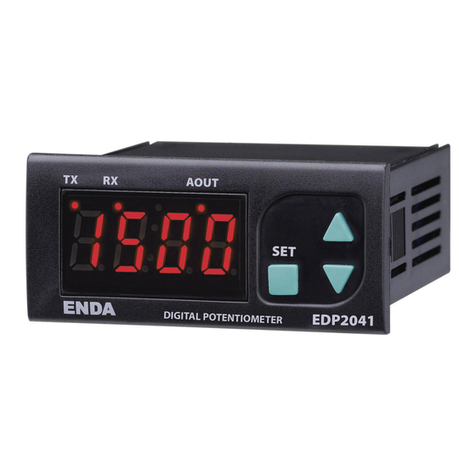
ENDA EDP2041 User manual

ENDA

ENDA EDP2041 User manual

ENDA ETI741 User manual

ENDA

ENDA ETI741 User manual

ENDA EDP 741C User manual

ENDA

ENDA EDP 741C User manual

ENDA EPV141 User manual

ENDA

ENDA EPV141 User manual

ENDA EPA741 User manual

ENDA

ENDA EPA741 User manual

ENDA ETS762 User manual

ENDA

ENDA ETS762 User manual

ENDA EPA742 User manual

ENDA

ENDA EPA742 User manual

ENDA ETS762 User manual

ENDA

ENDA ETS762 User manual

ENDA EPV241A User manual

ENDA

ENDA EPV241A User manual

ENDA EDP2041 User manual

ENDA

ENDA EDP2041 User manual

ENDA EPV742 User manual

ENDA

ENDA EPV742 User manual

ENDA EPA242 User manual

ENDA

ENDA EPA242 User manual

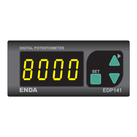
ENDA EDP 141 User manual

ENDA

ENDA EDP 141 User manual

ENDA ETS1410 User manual

ENDA

ENDA ETS1410 User manual

ENDA EPV741 User manual

ENDA

ENDA EPV741 User manual

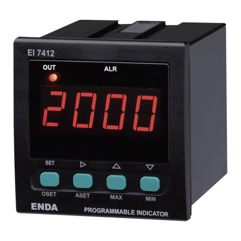
ENDA EI7412 User manual

ENDA

ENDA EI7412 User manual

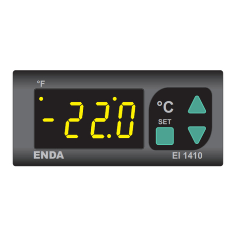
ENDA EI1410 NTC User manual

ENDA

ENDA EI1410 NTC User manual

ENDA EPA942 User manual

ENDA

ENDA EPA942 User manual

ENDA EPA141 User manual

ENDA

ENDA EPA141 User manual

ENDA EPV241A User manual

ENDA

ENDA EPV241A User manual

ENDA EDP2041 User manual

ENDA

ENDA EDP2041 User manual

ENDA EDP 141 User manual

ENDA

ENDA EDP 141 User manual

ENDA EI7412 User manual

ENDA

ENDA EI7412 User manual

Popular Measuring Instrument manuals by other brands

Mitutoyo LSM-9506 user manual

Mitutoyo

Mitutoyo LSM-9506 user manual

twintex VC9901 Operation manuals

twintex

twintex VC9901 Operation manuals

KMB SML 133 Series operating manual

KMB

KMB SML 133 Series operating manual

Ebtron GP1 Quick installation guide

Ebtron

Ebtron GP1 Quick installation guide

scienion sciREADER CL2 Original user manual

scienion

scienion sciREADER CL2 Original user manual

e-survey HP50 user manual

e-survey

e-survey HP50 user manual

VDO CONTISYS OBD - Quick reference guide

VDO

VDO CONTISYS OBD - Quick reference guide

SHANGHAI KIN YOUNG PHOTOELECTRIC KY3213N- A user manual

SHANGHAI KIN YOUNG PHOTOELECTRIC

SHANGHAI KIN YOUNG PHOTOELECTRIC KY3213N- A user manual

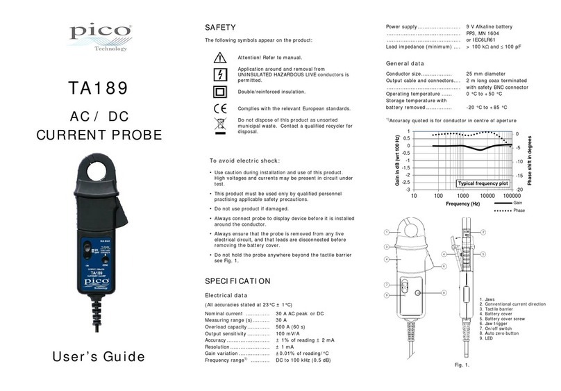
PICO TA189 user guide

PICO

PICO TA189 user guide

AXE MFRTS Series Operation manual

AXE

AXE MFRTS Series Operation manual

Altana BYK color2view operating instructions

Altana

Altana BYK color2view operating instructions

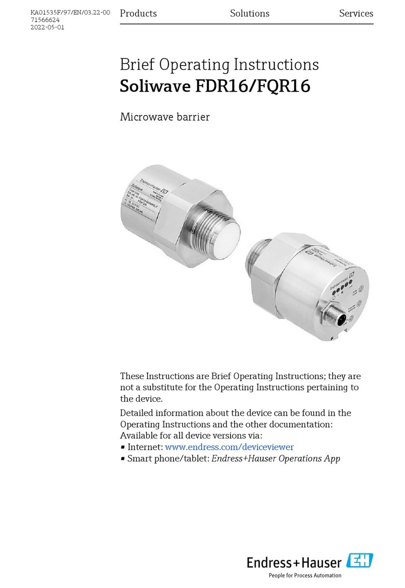
Endress+Hauser Soliwave FDR16 Brief operating instructions

Endress+Hauser

Endress+Hauser Soliwave FDR16 Brief operating instructions

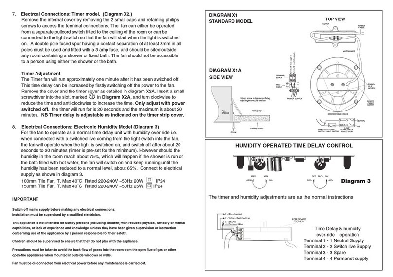
APL DIAGRAM X2 installation instructions

APL

APL DIAGRAM X2 installation instructions

Transforming Technologies OhmMETRICS EFM250 manual

Transforming Technologies

Transforming Technologies OhmMETRICS EFM250 manual

Tegam 710A quick start guide

Tegam

Tegam 710A quick start guide

Amphenol Wilcoxon TN14 Troubleshooting installations

Amphenol

Amphenol Wilcoxon TN14 Troubleshooting installations

WIRELESS TELECOM GROUP BOONTON 4540 Series quick start guide

WIRELESS TELECOM GROUP

WIRELESS TELECOM GROUP BOONTON 4540 Series quick start guide

Favero Electronics ASSIOMA UNO user manual

Favero Electronics

Favero Electronics ASSIOMA UNO user manual

manuals.online logo
manuals.online logoBrands
  • About & Mission
  • Contact us
  • Privacy Policy
  • Terms and Conditions

Copyright 2025 Manuals.Online. All Rights Reserved.