Cole Parmer PBL-602 User manual

User Manual
Cole-Parmer Symmetry
Portable Lab Balances: PBL Series
6-5-18 v5

GENERAL INFORMATION .................................................................................................................................1
INTENDED USE....................................................................................................................................1
PRECAUTIONS.....................................................................................................................................1
BATTERY ..............................................................................................................................................1
WARRANTYCONDITIONS....................................................................................................................1
UNPACKING ANDINSTALLATION....................................................................................................................2
PLACE OF USE AND ASSEMBLING....................................................................................................2
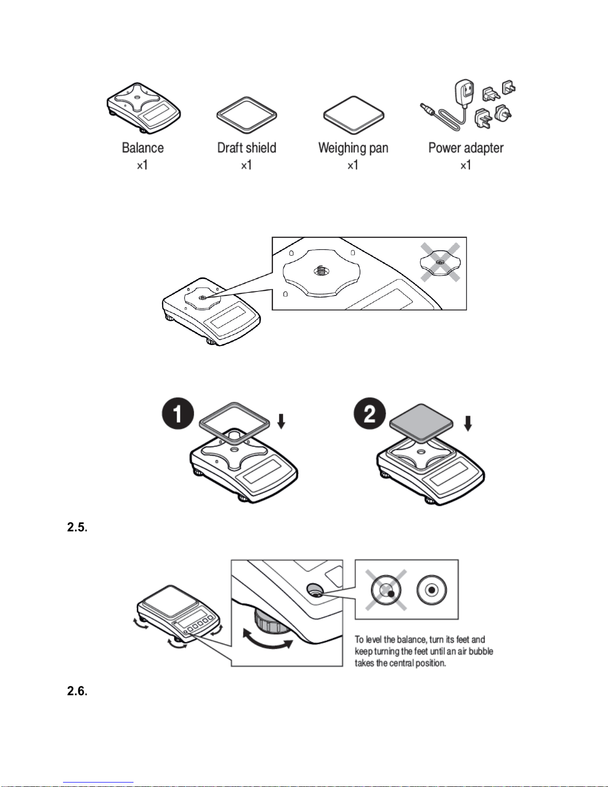
STANDARD DELIVERY COMPONENTS LIST.....................................................................................2
UNPACKING..........................................................................................................................................2
BALANCE ASSEMBLY..........................................................................................................................3
BALANCE LEVELING ...........................................................................................................................4
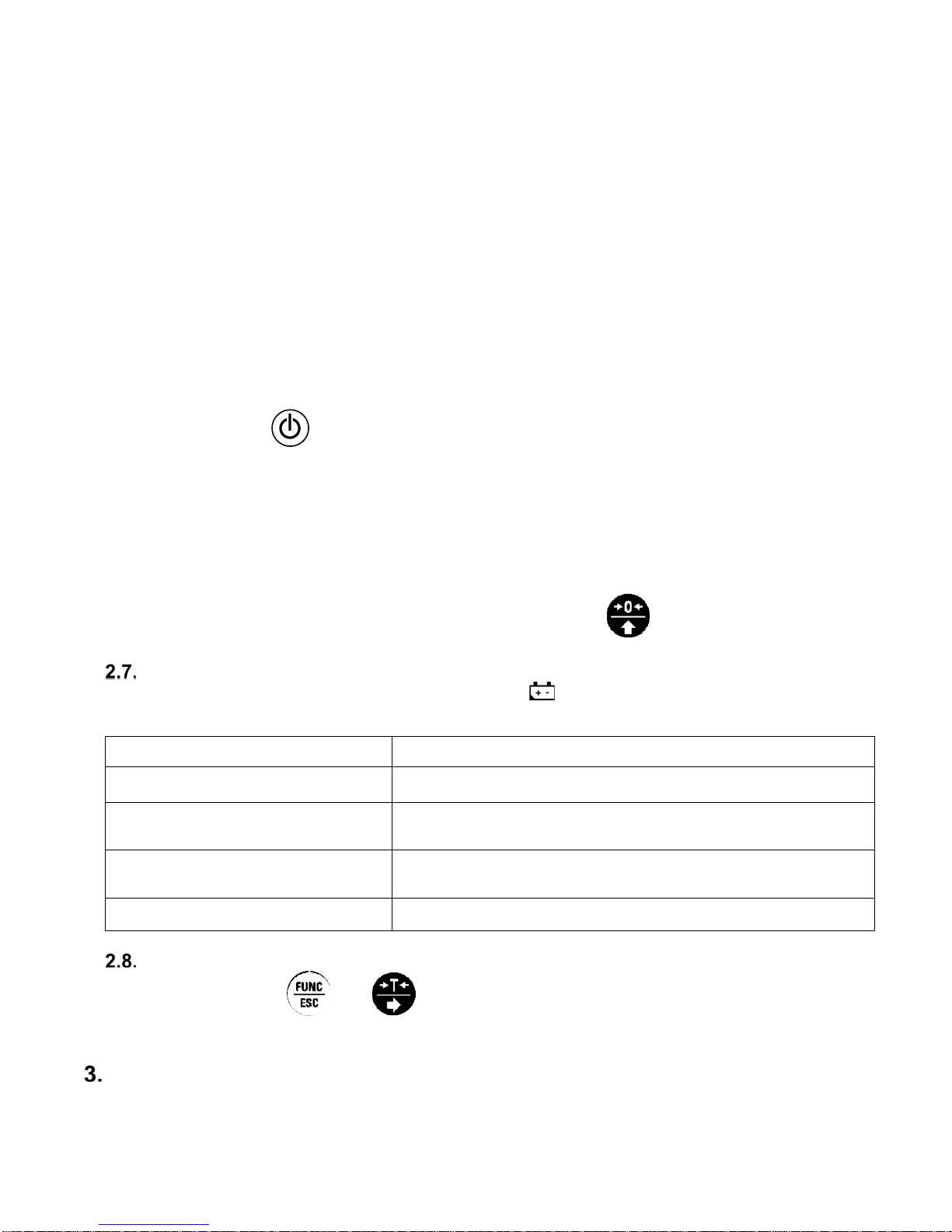
POWERING THE DEVICE ....................................................................................................................4
BATTERY STATUS...............................................................................................................................5
BATTERY POWER................................................................................................................................5
BALANCE CONTROL.........................................................................................................................................5
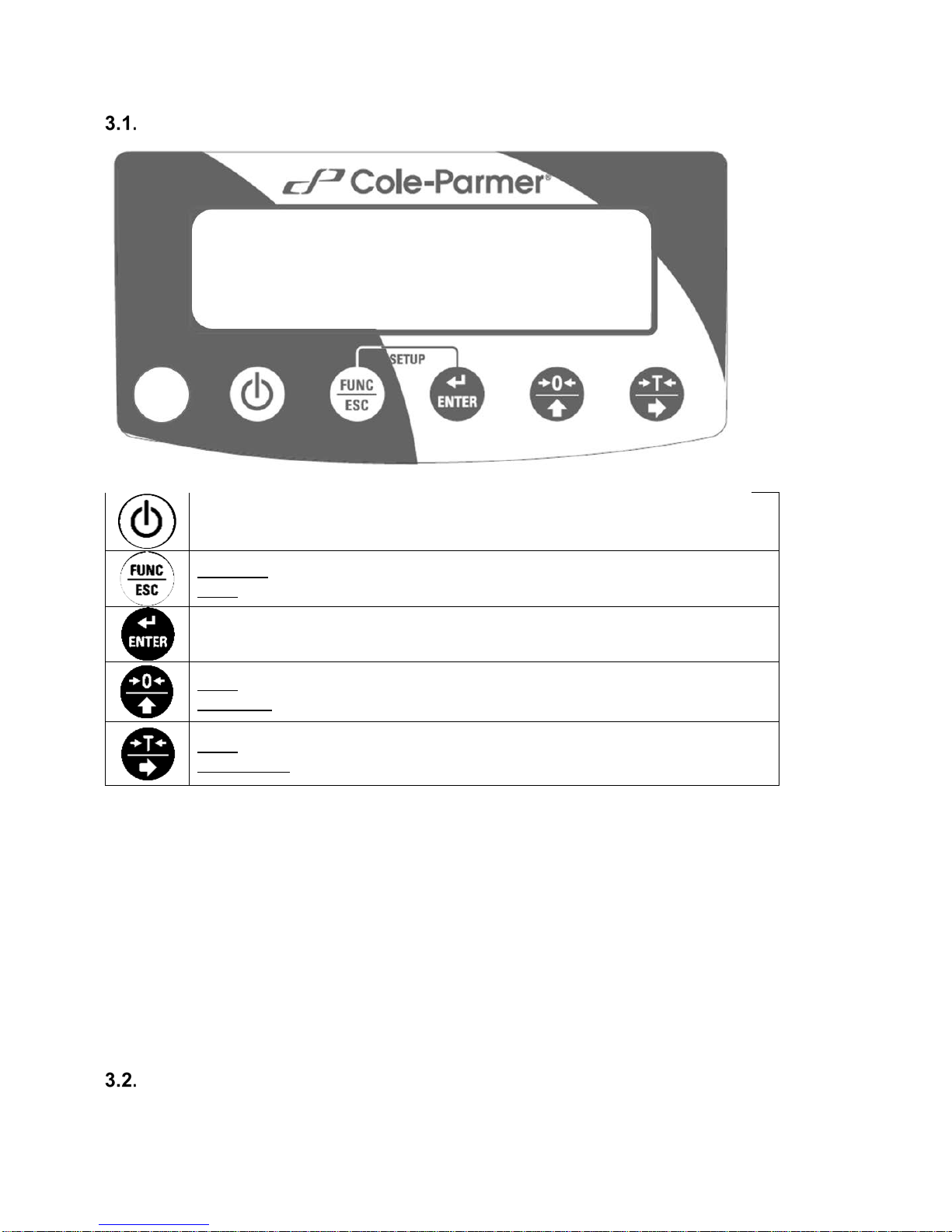
BALANCE KEYBOARD.........................................................................................................................6
NAVIGATING BALANCE MENUS.........................................................................................................6
BALANCE MENU...................................................................................................................................7
WEIGHING MODE...............................................................................................................................................9
UNITS ................................................................................................................................................. 10
START UNIT....................................................................................................................................... 10
TEMPORARY UNIT............................................................................................................................ 10
TARING .............................................................................................................................................. 11
MANUAL TARE ENTERING............................................................................................................... 11
ZEROING............................................................................................................................................ 12
BALANCEPARAMETERS............................................................................................................................... 12
FILTER LEVEL ................................................................................................................................... 12
VALUE RELEASE............................................................................................................................... 12
BALANCE AMBIENT CONDITIONS .................................................................................................. 13
AUTOZERO........................................................................................................................................ 13
TARE .................................................................................................................................................. 13
LAST DIGIT ........................................................................................................................................ 14
ADJUSTMENT.................................................................................................................................................. 14
EXTERNAL ADJUSTMENT................................................................................................................ 14
USER ADJUSTMENT......................................................................................................................... 16
ADJUSTMENT REPORT.................................................................................................................... 16
WORKINGMODES........................................................................................................................................... 16
RUNNING WORKING MODE............................................................................................................. 17
WORKING MODE ACCESSIBILITY................................................................................................... 17
SAVE MODE....................................................................................................................................... 18
AUTOMATIC PRINTOUT TIME INTERVAL....................................................................................... 19
LO THRESHOLD................................................................................................................................ 19
WEIGHING ......................................................................................................................................... 20
7.6.1 SETTINGS.......................................................................................................................................... 20
7.7 . PARTS COUNTING .................................................................................................................................. 20
7.7.1 SETTINGS.......................................................................................................................................... 20
7.7.2 OPERATION MODE........................................................................................................................... 21
7.7.3 SETTING REFERENCE MASS BY ENTERING MASS OF A SINGLE PART.................................. 21
7.7.4 SETTING REFERENCE MASS BY DETERMING MASS OF A SINGLE PART............................... 21
7.8 . +/- CONTROL............................................................................................................................................ 22
7.8.1 SETTINGS.......................................................................................................................................... 22
7.8.2 DECLARING CHECKWEIGHING THRESHOLDS............................................................................. 22
7.9 . PERCENT WEIGHING AGAINST REFERENCE SAMPLE MASS........................................................... 23
7.9.1 SETTINGS.......................................................................................................................................... 23
INDEX

1
7.9.2 OPERATION MODE........................................................................................................................... 23
7.9.3 REFERENCE SAMPLE MASS DETERMINED BY WEIGHING........................................................ 24
7.9.4 REFERENCE SAMPLE MASS DETERMINED BY ENTERING MASS VALUE................................ 24
7.10 PEAK HOLD ....................................................................................................................................... 24
7.10.1 SETTINGS........................................................................................................................................ 24
7.10.2 MEANS OF OPERATION................................................................................................................. 25
7.11 TOTALIZING....................................................................................................................................... 25
7.11.1 SETTINGS........................................................................................................................................ 25
7.11.2 MEANS OF OPERATION................................................................................................................. 25
INTERFACES ................................................................................................................................................... 26
RS232................................................................................................................................................. 26
8.1.1 BAUD RATE....................................................................................................................................... 27
8.1.2 PARITY............................................................................................................................................... 27
USB A PORT ...................................................................................................................................... 27
8.2.1 IMPORT / EXPORT............................................................................................................................ 28
USB B PORT ...................................................................................................................................... 29
PERIPHERALS................................................................................................................................................. 29
COMPUTER ....................................................................................................................................... 29
9.1.1 COMPUTER PORT............................................................................................................................ 29
9.1.2 CONTINUOUS TRANSMISSION....................................................................................................... 29
9.1.3 PRINTOUT INTERVAL FOR CONTINUOUS TRANSMISSION........................................................ 30
9.2 PRINTER..................................................................................................................................................... 30
9.2.1 PRINTER PORT................................................................................................................................. 30
PRINTOUTS................................................................................................................................................ 30
ADJUSTMENT REPORT PRINTOUT................................................................................................ 30
GLPPRINTOUT.................................................................................................................................. 31
BALANCE SETTINGS................................................................................................................................ 32
BACKLIGHT........................................................................................................................................ 32
'BEEP' SOUND................................................................................................................................... 32
AUTOMATIC SHUTDOWN ................................................................................................................ 33
DATE .................................................................................................................................................. 33
TIME ................................................................................................................................................... 33
DATE FORMAT .................................................................................................................................. 34
TIME FORMAT ................................................................................................................................... 34
USER MENU DEFAULT SETTINGS.................................................................................................. 34
INFORMATION ........................................................................................................................................... 34
APPENDIX .................................................................................................................................................. 35
BALANCE SPECIFICATIONS............................................................................................................ 35
MAITENANCE .................................................................................................................................... 35
13.2.1 CLEANING ABS COMPONETS....................................................................................................... 35
13.2.2 CLEANING STAINLESS STEEL COMPONETS ............................................................................. 36
ACCESSORIES.................................................................................................................................. 36
DIMENSIONS..................................................................................................................................... 36
CONNECTORS .................................................................................................................................. 37
TROUBLESHOOTING........................................................................................................................ 38
ERRORMESSAGES.......................................................................................................................... 38
WARRANTY CARD............................................................................................................................ 38

1
GENERAL INFORMATION
INTENDED USE
ThePBL-Series precision balance enables fast and accurate mass measurements under
laboratoryconditions.
The weighing pan, made of stainless steel and equipped with anti-draft shield, is an integral part of
the PBL-series balance. Backlit LCD display ensures clear measurement result. The PBL-Series
balance is equipped with an internal battery (comes standard), so it does not have to be connected
to themains.
The PBL-series balance is equipped with the following interfaces: RS 232, USB type A, USB type
B. The interfaces enable cooperation between the balance and peripheral devices (e.g. printer,
computer, flash drive).
PRECAUTIONS
•Prior to first use, it is highly recommended to carefully read this User Manual, and
operate the balance as intended.
•Do not use the balance for a dynamic weighing. Even if small quantities of weighed
material are added or removed from the weighing pan of the instrument, the reading
should be taken only after stabilization of the measurement results.
•While loading the balance make sure that load is placed in the very center of the
weighing pan.
•Make sure the load does not exceed instrument’s measuring range (maximum
capacity).
•Do not leave heavy loads on the weighing pan for a long period of time.
•In case of failure, immediately unplug the instrument.
•Balances to be decommissioned, should be decommissioned in accordance with valid
legal regulations.
•Do not use the balance is areas endangered with explosion. The balance is not
designed to operate in EX zones.
BATTERY
The PBL-Series balance is supplied by NiMH-type battery (nickel-metal- hydrogen) of 1800-
2800mAh capacity.
In case of prolonged storage of the balance in low temperature, the battery must be
charged.
A worn-out battery can be replaced only by the manufacturer or by the authorized
service.
The equipment including accumulators does not belong to regular household waste.
The European legislation requires electric and electronic equipment to be collected
and disposed separately from other communal waste with the aim of being recycled.
Notice:
Symbols on accumulators identify harmful compounds: Pb = lead, Cd = cadmium, Hg = mercury.
WARRANTYCONDITIONS

2
Cole-Parmer will exchange, replace or repair the existing balance for any damage that appears to be
faulty by production or by construction within the 5-year warranty period.
Warranty is voided if:
A. Cole Parmer will exchange, replace or repair the existing balance for any damage that
appears to be faulty by production or by construction within the 5-year warranty period.
B. Warranty is voided if:
•mechanical defects caused by inappropriate use:
• defects of thermal and chemical origin,
• defects caused by lightning, overvoltage in the power network
• defects caused by water damage
• or other random event
•overloading the mechanical measuringsystem
•installing another version of the operating system
•utilizing the balance contrary to its intendeduse
•repairs carried out by non-authorized service centers
•removing or destroying protective stickers which secure the balance’s housing against
unauthorizedaccess
C. Warranty card must be filled out for warranty to be valid.
UNPACKING AND INSTALLATION
PLACE OF USE AND ASSEMBLING
•The balance should be stored and used in locations free of vibrations and shakes, free
of air movement and dust.
•Ambient air temperature should not exceed the range of: +15 °C to +30 °C.
•Ambient relative humidity should not exceed 80%.
•During balance operation, ambient temperature in the weighing room should not change
rapidly.
•The balance should be located on a stable wall console desk or a stable working table
which is not affected by vibrations and distant from heat sources.
•Keep all package element should your device be transported in the future. Remember
that only original packaging can be used for shipping purposes. Prior to packing,
uncouple any cables, remove any separable components (weighing pan, shields,
inserts). Pack the device components into an original packaging. The original packaging
protects the equipment against potential damage during transportation.
STANDARD DELIVERY COMPONENTS LIST
•Balance and components shown in Section 2.4 depending on balance model
•Warranty Card
•USB
oUser Manual
oBalance USB Driver
oRLAB Software
oUSB COM Driver
UNPACKING
To unpack the system, follow the diagram below-

3
BALANCE ASSEMBLY
Model: PBL-203
Components:
Installation:
1) Check grounding spring to insure it is in the appropriate location. Make sure that the
grounding spring juts slightly out of the hole.
2) Install components following diagram below:
i. Draft Shield
ii. Weighing Pan
Model: PBL-602, PBL-2002, PBL-3101, PBL-602.N, PBL-2002.N, PBL-3101.N
Components:

4
Installation:
1) Check grounding spring to insure it is in the appropriate location. Make sure that the
grounding spring juts slightly out of the hole.
2) Install components following diagram below:
i. Draft Shield
ii. Weighing Pan
BALANCE LEVELING
It is necessary to level the balance prior to plugging it in. To level the balance, turn its feet until the
air bubble is in the center position.
The balance should firmly rest on a surface, each of the feet must be supported.
POWERING THE DEVICE
Before plugging in your balance, it is imperative to wait until the balance reaches thermal stabilization

5
(estimated 1-8 hours). On switching on, the balance requires 30 minutes oftemperature stabilization
time. During temperature stabilization displayed information maychange. Adjustment should be
carried out after temperaturestabilization.
For correct operation of the balance the temperature range is +15˚C to +30˚C;
Any changes of temperature and humidity during operation can cause indication errors. Errors can
be corrected by carrying out user adjustment.
For balances that were stored in much lower temperatures (e.g. during winter period), thermal
stabilization period may be extended.
•Balance should be plugged in only with the power adapter that comes standard
with the model. Nominal power supply of the power adapter (specified on the
power adapter data plate) should be compatible to the power supply.
•Plug the balance in – connect the power adapter to the socket, next connect its
connector to port located at the back of the balance housing.
•Press button on the key pad.
!Remember to start the balance with no load on the weighing pan
•Test of the display unit takes place right after connecting the balance to the power,
all the elements and pictograms are backlit for a short time.
•Next, the name and the program number appears
•the indication gets to ZERO (displayed reading unit depends on the balance).
During the balance start, the test of an internal mass adjustment mechanism
occurs (single location and elevation of the internal mass adjustment).
•If the indication is different than zero, please press button
BATTERY STATUS
An internal battery comes standard with the balance. pictogram, displayed at the top of the
display, signals batterystatus.
Pictogram operation Overview
No pictogram Battery full. Standard balance operation.
Pictogram displayed continuously Battery status low. The balance will shut down.
Immediately charge the battery.
Pictogram blinks every 1 s. Battery charging. Balance connected to power supplier,
the battery is being charged.
Pictogram blinks every 0.5 s. Battery error. Battery damaged.
BATTERY POWER
•
Simultaneously
and
keys.
•Battery power given in % is displayed for2s.
•Wait for the home screen to bedisplayed.
BALANCE CONTROL

6
BALANCE KEYBOARD
Press to switch the balance on/off
Function: press to select working mode.
ESC: Exit out of menus/submenus
Press to send the weighing result to a printer or a computer.
Zero: press to zero the balance.
Up arrow: move up the menu or submenu
Tare: press to tare the balance.
Right arrow: enter into menu or submenu or select parameter to modify
NAVIGATING BALANCE MENUS
Use keypad to navigate in the balances menus and submenus.

7
+ Simultaneously press to enter 'Main Menu'
Press to move upwards within balance menus and submenus
Press to enter submenu
Press to confirm introduced modifications
Press to move one menu level up
BALANCE MENU
Main menu is divided into function groups. Function group is a group of interrelated parameters.

8
Main Menu
Submenus
Options
Overview
Additional Info
P1.
CAL
Adjustment
1.1.
CA-E
External adjustment
Section 6.1
1.2.
CA
-U
User adjustment with external
weight
Section 6.2
P2.
rEAd
Balance parameters
2.1.
FIL
1, 2, 3
Filter
Section 5.1
2.2.
APPr
FASt, PrEc, F_P
Value release
Section 5.2
2.3.
Enut
StAb, nStAb
Environment
Section 5.3
2.4.
Aut
YES, no
Autozero
Section 5.4
2.5.
tare
no, tArF, AtAr, EAcH
Tare
Section 5.5
2.6.
ttr
tArEH, tArnn
Tare implementing method
Section 5.5
2.7.
LdiG
ALAS, nEur, uuSt
Last digit
Section 5.6
P3.
Func
Working modes
3.1.
UUGG
Weighing
Section 7.6
3.1.1.
Acc
YES, no
Working mode On/Off
Section 7.2
3.1.2.
Snn
StAb, nStAb, rEPL
Save mode
Section 7.3
3.1.3.
Int
Automatic Printout Time Interval
Section 7.4
3.1.4
Lo
LO Threshold
Section 7.5
3.2.
PCS
Parts counting
Section 7.7
3.2.1.
Acc
YES, no
Working mode On/Off
Section 7.2
3.2.2.
UUT
S_s, Suu
Operation mode
Section 7.7.2
3.2.3.
Snn
StAb, nStAb, rEPL
Save mode
Section 7.3
3.2.4.
Int
Automatic Printout Time Interval
Section 7.4
3.2.5.
Lo
LO Threshold
Section 7.5
3.3.
HiLo
+/- control
Section 7.8
3.3.1.
Acc
YES, no
Working mode On/Off
Section 7.2
3.3.2.
Snn
StAb, nStAb, rEPL
Save mode
Section 7.3
3.3.3.
Int
Automatic Printout Time Interval
Section 7.4
3.3.3.
Lo
LO Threshold
Section 7.5
3.4.
dEu
Percent weighing
Section 7.9
3.4.1.
Acc
YES, no
Working mode On/Off
Section 7.2
3.4.2.
UUT
S_s, Suu
Operation mode
Section 7.9.2
3.4.3.
Snn
StAb, nStAb, rEPL
Save mode
Section 7.3
3.4.4.
Int
Automatic Printout Time Interval
Section 7.4
3.4.5.
Lo
LO Threshold
Section 7.5
3.5.
toP
Peak hold
Section 7.10
3.5.1.
Acc
YES, no
Working mode On/Off
Section 7.2
3.5.2.
Lo
LO Threshold
Section 7.5
3.6.
Add
Totalizing
Section 7.11
3.6.1.
Acc
YES, no
Working mode On/Off
Section 7.2
3.6.2.
Snn
StAb, nStAb, rEPL
Save mode
Section 7.3
3.6.3.
Int
Automatic Printout Time Interval
Section 7.4
3.6.4.
Lo
LO Threshold
Section 7.5
P4.
Conn
Interfaces
4.1.
rS
RS232 parameters settings
Section 8.1

9
4.1.1.
bAd
2400, 4800, 9600,
19200, 38400,
RS 232 baud rate
Section 8.1.1
4.1.2.
PAr
nonE, Odd, EuEn
Parity
Section 8.1.2
P5.
ducE
Peripherals
5.1.
PC
Computer
Section 9.1
5.1.1.
Prt
nonE, rS232, USbB
Computer port
Section 9.1.1
5.1.2.
Cnt
nonE, CntA, Cntb
Continuous Transmission
Section 9.1.2
5.1.3.
Int
0.1[s] - 1000[s]
Continuous transmission time
Section 9.1.3
5.2.
Prtr
Printer
Section 9.2
5.2.1.
Prt
nonE, rS232, USbb
Printer port
Section 9.2.1
P6.
Prnt
Printouts
6.1.
CrEP
Adjustment report
Section 10.1
6.1.1.
CtP
YES, no
Adjustment type
6.1.2.
dAt
YES, no
Date
6.1.3.
tin
YES, no
Time
6.1.4.
Idb
YES, no
Balance S/N
6.1.5.
CdF
YES, no
Adjustment difference
6.1.6.
dSh
YES, no
Dashes
6.1.7.
SiG
YES, no
Signature
6.2.
GLP
GLP Printout
Section 10.2
6.2.1.
dAt
YES, no
Date
6.2.2.
tin
YES, no
Time
6.2.3.
n
YES, no
Net
6.2.4.
t
YES, no
Tare
6.2.5.
b
YES, no
Gross
6.2.6.
CrS
YES, no
Current result
6.2.7.
CrP
YES, no
Adjustment report
P7.
Misc
Miscellaneous
7.1.
bLbt
no, 10, 20, 30, 40,
50,
60, 70, 80, 90,
100
Backlit level in [%]
Section 11.1
7.2.
bEEP
YES, no
Key sound
Section 11.2
7.3.
t1
nonE, 1, 2, 3, 5, 10
Automatic Shutdown
Section 11.3
7.4.
SdAt
Date
Section 11.4
7.5.
Stnn
Time
Section 11.5
7.6.
FdAt
1, 2, 3, 4
Date format
Section 11.6
7.7.
Ftin
12H, 24H
Time format
Section 11.7
7.8.
dFLu
User default settings
Section 11.8
P8.
InFo
Information on balance
8.1.
Idb
Balance serial number
Section 12
8.2.
PurS
Program version
Section 12
P9.
Unit
Units
9.1.
UnSt
g, kg, N, ct, lb
Start unit
Section 4.2
9.2.
Unin
g, kg, N, ct, lb
Temporary unit valid until the
balance is turned off.
Section 4.3
WEIGHING MODE
Load the weighing pan. You can read weighing result when , pictogram is displayed. To assure
long-term operation and correct mass measurements follow the rules presented below:

10
•
Load the weighing pan steadily avoiding shocks:
•
Place weighed loads centrally on the weighing pan (eccentricity errorsare specified by PN-EN
45501 standard, points 3.5 and3.6.2.):
•
Do not load the pan with concentratedforce:
•
Avoid side loading, in particular side shocks:
UNITS
<P9.Unit> parameters group enables selecting start and temporary unit. Selecting unit other than [g]
is possible during weighing or during other modes operation. 'Parts counting' and 'Percent weighing'
modes are exceptions for which the unit cannot be changed.
START UNIT
Setting the start unit.
Procedure:
•To enter menu navigation, follow process found in Section 3.2 (page 7). Enter <P9.Unit /
9.1.UnSt>submenu.
•
Press
key to view available units: [g,ct,lb]
•On selecting start unit, press key to confirm. Next, press key to return to
home screen.
•The balance turns on with start unitselected.
TEMPORARY UNIT
Temporary unit remains active until the balance is turned off.
Procedure:

11
•To enter menu navigation, follow process found in Section 3.2 (page 7). Enter <P9.Unit /
9.2.Unin>submenu.
•Press key to view availableunits: [g,ct,lb]
•On selecting start unit, press key to confirm and return to home screen
TARING
To determine net mass, put the packaging on the weighing pan. On stabilizing,
press
key
(indication changes to zero, Net pictogram is displayed in the left upper corner):
On loading the weighing pan, net mass is displayed. You can tare repeatedly within the whole
measuring range. While using tare function remember not to exceed the maximum measuring range
of the balance. On unloading the weighing pan, the sum of tared masses with minus sing is displayed.
Caution:
Taring cannot be performed when the displayed value is negative or equal zero. In such case
message Err3 is displayed and short signal isemitted.
MANUAL TARE ENTERING
Manual entering of tare value within the balance.
Procedure:
•Simultaneously press
and
keys.
•Using and keys set tare value
•Press key,
•Balance returns to weighing mode. Tare value with '-' sign is displayed.

12
•Tare can be entered at any moment during the weighingprocess.
Caution:
Tare cannot be entered manually when tare value is already implemented to balance's memory. In
such case message <Err3> is displayed and a short signal is emitted.
ZEROING
To zero mass indication press . key. Zero value and following pictograms
and are
displayed. It is possible to zero the balance only when the
indication isstable.
Caution:
Indication can be zeroed only within ±2% range of maximum capacity. If the zeroed value is greater
than ±2% of the maximum capacity, message <Err2> is displayed and short signal is emitted.
BALANCE PARAMETERS
You can adjust the balance to ambient conditions (filter level) or to your own needs (autozero, tare
value). The parameters are to be found in <P2.rEAd> submenu.
FILTER LEVEL
Filter settings adjustment depends on the working environment. For the best possible conditions,
the filter can work in fast mode. For conditions that are poor, the filter should be set to slow.
•To enter menu navigation, follow process found in Section 3.2 (page 7). Enter <P2.rEAd
/ 2.1.FiL>submenu
•
Press
key to view available filter values:
1 - fast
2 - average
3 – slow
•
Press
key to confirm. Return to home screen.
Caution:
The higher filter level, the longer the indication takes to stabilize.
VALUE RELEASE
Parameter related with the stabilization rate of measurement result. Depending on the selected
option, weighing time is either shorter or longer.

13
Procedure:
•To enter menu navigation, follow process found in Section 3.2 (page 7). Enter <P2.rEAd
/ 2.2.APPr>submenu.
•
Press
key to view availableoptions:
F_P -Fast andreliable
PrEc- Reliable
FASt- Fast
•
Press
key to confirm. Return to home screen.
BALANCE AMBIENT CONDITIONS
Parameter relating to ambient and environmental conditions in which the balance operates. If the
ambient conditions are unstable (air drafts, vibrations), select 'unstable' option.
Procedure:
•To enter menu navigation, follow process found in Section 3.2 (page 7). Enter <P2.rEAd
/ 2.3.Enut>submenu.
•
Press
key to view available options:
nStAb – unstable
StAb –stable.
•
Press
key to confirm. Return to home screen.
AUTOZERO
The balance features an autozero function (Auto) ensuring precise mass indication. This function
automatically controls and corrects zero indication.
There are, however, some cases when this function can be a disturbing factor for the measuring
process; e.g. very slow placing of a load on the weighing pan (load adding). In such case, it is
recommended to disable the function.
Procedure:
•To enter menu navigation, follow process found in Section 3.2 (page 7). Enter <P2.rEAd
/ 2.4.Aut>submenu.
•
Press
key to view available options:
YES – function enabled
no – function disabled
•
Press
key to confirm. Return to home screen.
TARE
Function enables setting appropriate parameters related with taring.

14
Procedure:
•To enter menu navigation, follow process found in Section 3.2 (page 7). Enter <P2.rEAd
/ 2.5.tArA>submenu.
•
Press
key to view availableoptions:
no- Basic tare mode. Set (selected) tare value is overwritten on
entering new tarevalue.
tArF- Last tare value is stored in balance's memory. Tare value is
automatically
displayed on restarting the balance.
AtAr- Tare value is saved after the power supply is disconnected.
EAcH- Automatic taring of each approved measurement.
•
Press
key to confirm. Return to home screen.
LAST DIGIT
Function enables displaying the last digit of decimal place for a weighing result the measurement is
carried out with lesseraccuracy.
Procedure:
•To enter menu navigation, follow process found in Section 3.2 (page 7). Enter <P2.rEAd
/ 2.6.LdiG>submenu.
•
Press
key to view availableoptions:
ALAS - All digitsvisible
nEur - Last digit is notdisplayed
uuSt - Last digit is displayed only for a stable weighing result
•
Press
key to confirm. Return to home screen.
ADJUSTMENT
In order to ensure the highest weighing accuracy, it is recommended to periodically introduce a
corrective factor of indications to balance memory, the said factor must be referred to a reference mass.
It is a balance adjustment.
Adjustment has to be carried out:
•
Prior to weighing
•
If long breaks between following measuring seriesoccur
•
If the ambient temperature has changeddynamically
•
If the balance's place of use haschanged
Types of adjustment:
•
External adjustment <1.1.CA-E> carried out with external weightof declared mass which
cannot bemodified.
•
User adjustment <1.2.CA-u> carried out with any external weight of mass equal or greater than
30% of maximumcapacity.
EXTERNAL ADJUSTMENT
External adjustment is carried out using external weight of class F1.

15
Procedure:
•To enter menu navigation, follow process found in Section 3.2 (page 7). Enter <P1.CAL /
1.1.CA-E> submenu.
•Message <UnLoAd> (unload the weighing pan) is displayed. On unloading the weighing
pan, press key.
•Balance starts determining mass of an empty weighing pan. The process is signaled by
dashes <- >. Next, message <Load> (put weight) is displayed along with mass value to
be put onto weighing pan; e.g.. 200.000g (depending on balance type). Put the weight of
a given mass and press key.
•Balance starts determining mass of a weight. The process is signaled by dashes <- >.
Next, message <UnLoad> (remove weight) isdisplayed.

16
•On unloading the weighing pan, submenu <1.1.CA-E> isdisplayed.
USER ADJUSTMENT
User adjustment is carried out using external weight of class F1.
Procedure:
•To enter menu navigation, follow process found in Section 3.2 (page 7). Enter <P1.CAL /
1.2.CA-u> submenu. Message box for entering mass of a weight used for user
adjustment is displayed. Mass of the weight has to be equal or greater than 30% of
maximumcapacity.
•On entering and confirming the weight mass, message <UnLoAd> (unload the weighing
pan) is displayed.
•On unloading the weighing pan, press key.
•Balance starts determining mass of an empty weighing pan. The process is signaled by
dashes <- >. Next, message <Load> (put weight) is displayed along with declared mass
value to be put onto weighing pan; e.g.. 100.000g.
•Put the weight of a given mass and press key.
•Balance starts determining mass of a weight. The process is signaled by dashes <- >.
Next, message <UnLoad> (remove weight) isdisplayed.
•On unloading the weighing pan submenu<1.2.CA-u> isdisplayed.
ADJUSTMENT REPORT
Adjustment report is automatically printed on a printer connected to the balance at the end of each
adjustment. Report content is to be declared in <P6.1.CrEP> menu and described further down
this user manual.
WORKING MODES
The balance features the following working modes:

17
•
Weighing <UUGG>
•
Parts counting <PCS>
•
+/- control <HiLo>
•
Percent weighing <dEu>
•
Peak hold <toP>
•
Totalizing <Add>
RUNNING WORKING MODE
Procedure:
Caution:
The balance is restarted with the last working mode activated.
WORKING MODE ACCESSIBILITY
Within each working mode, accessibility of the working mode can be adjusted.
YES – working mode enabled
no- working Mode Disabled
Procedure:
This manual suits for next models
5
Table of contents
Other Cole Parmer Scale manuals

Cole Parmer
Cole Parmer MB-800 Series User manual

Cole Parmer
Cole Parmer LB-200 Series User manual

Cole Parmer
Cole Parmer IPSW-400 Series User manual

Cole Parmer
Cole Parmer Balance LA Series User guide

Cole Parmer
Cole Parmer TA-225.C User guide

Cole Parmer
Cole Parmer CS-200 User manual

Cole Parmer
Cole Parmer IBS-200 User manual

Cole Parmer
Cole Parmer B2 Series User guide

Cole Parmer
Cole Parmer IPSW Series User manual

Cole Parmer
Cole Parmer TA-225.C User manual