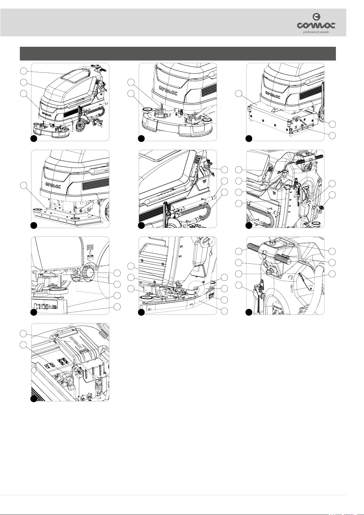
LABELS USED ON THE MACHINE
Main switch symbol:
Used by the control handlebars to indicate the main switch on the machine.
-Chiudere il rubinetto a fine lavoro
-Turn off the cock when operations are finished
-Cierrese el grifo al finalizar el trabajo
-Fermer le robinet a la fin du travail
-Den Hahn bei Arbeitsschluss schliessen
-Pulire giornalmente il tergipavimento e i filtri
-Clean the squeegee and the filters
-Limpiar a diario la boquilla de secado y los filtros
-Nettoyer le suceur et les filtres tous les jours
-Taegliche Reinigung des Saugfusses und der Filter
Label for detergent solution tap command:
Used on the rear right-hand side of the machine to identify the detergent solution tap control lever.
Label indicating the need to read the Use and Maintenance Manual:
Used above the recovery tank, near the control handlebar, to indicate to the operator that he/she must read the use and
maintenance manual before using the machine.
ATTENZIONE
Le batterie emettono gas di idrogeno infiammabile. Ne può risultare un incendio o un
esplosione. Tenere scintille e fiamme libere lontane quando la macchina è in carica.
Disconnettere il cavo delle batterie e del carica batterie prima di eseguire la
manutenzione
Non caricare le batterie con il cavo danneggiato
ATTENTION!
Batteriesemit flammacle hydrogen gas. Explosion or fire can result. Keep sparks and
open flame away when charging
Disconnect battery cables and charger plug before servicing machine
Do not charge batteries with damaged cord
¡ATENCIÓN!
Les batteries émettent gaz inflammables. Cela peut provoquer un incendie ou une
explosion.Gardez des étincelles et des flammes à distance lorsque la machine est en
charge.
Débranchez le câble de la batterie et du chargeur avant d'effectuer la manutention.
Ne charger pas les batteries dans le cas où les câbles soient endommagés.
ACHTUNG!
Batterienentwickeln entzündbare Gase. Es kann zu einem Brand oder einer Explosion
führen. Halten Sie Funken und offene Flammen, während der Batterieladung.
Trennen Sie die Kabel der Batterie und Ladegerät Bevor jede Wartung.
Die Batterien nicht laden mit beschädigten Batteriekabeln.
Battery recharge warning label:
This is located inside the machine above the recovery tank, near the batteries, to indicate to the operator that he/she must pay
attention when performing the battery recharge cycle.
RICARICA DELLE BATTERIE
Disinserire il connettore di alimentazione della macchina e collegare il
caricabatterie.
BATTERYCHARGING
Remove the power supply connector of the machine and connect the
battery charger.
CARGA DE LA BATERIA
Quitar el conector de alimentación de la máquina y conectar el
cargador de baterias.
RECHARGE DES BATTERIES
Detacher le connecteur d’alimentation de la machine et brancher le
chargeur des batteries.
WIEDERAUFLADEN DER BATTERIEN
Den Ladestecker der Maschine abschalten und mit dem Ladegeraet
verbinden.
Battery charging sequence label (versions without Battery Charger):
This is located inside the machine above the recovery tank, near the batteries, to indicate to the operator the sequence to be
followed in order to charge the batteries correctly.
ATTENZIONE: caricare la batteria solamente quando il display o le
spie sul cruscotto indicano il livello zero. Il tempo di ricarica della
batteria deve essere di minimo 12 ore. Attendere sempre
l’accensionedel led verde prima di considerare terminata la ricarica.
WARNING:charge the battery only when the display or the lights of
the instrument board indicate level zero. Charge time of the battery
must be at least 12 hours. Always wait for the switching on of the
greenled, only then the recharge has been completed.
ATENCIÓN:cargar la batería solamente cuando el señal baterías y
lasluces pilotos sobre el tablero de instrumentos indican el nivel cero.
El tiempo de carga de la batería será de 12 horas como mínimo.
Esperar siempre el encendido de la led vierde antes que considerar
larecarga terminada.
ATTENTION: charger la batterie seulement quand le témoin de
batterieou la lampe témoin sur le tableau de bord indiquent le niveau
zéro.Le temps de recharge de la batterie doit être au minimum de 12
heures.Attendre toujours l’allumage du led vert avant de considérer
larecharge terminée.
ACTHTUNG:die Batterie darf nur geladen werden, wenn die Batterie
Standsanzeigeoder die Batteriekontrollleuchte den
Batteriestand von Null signalisiert. Die Ladezeit der Batterie muß
mindestens 12 Stunden betragen. WartenSie immer bis die Anzeige
grünaufleuchtet, erst dann ist die Ladung vollständing durchgeführt.
Battery charging sequence label (versions with battery charger):
This is located inside the machine above the recovery tank, near the batteries, to indicate to the operator the sequence to be
followed in order to charge the batteries correctly.
ATTENZIONE!
È fattoassoluto divieto di aspirare/raccogliere con questo
apparecchiopolveri e/o liquidi infiammabili e/o esplosivi
o particelle incandescenti.
ATTENTION!
It is absolutely forbidden to suck/pick up inflammable
and/orexplosive liquid and/or solid substances or aflame
particles with this machine.
¡ATENCIÓN!
Queda terminantemente prohibido aspirar/recoger con
esta maquina polvo y/o líquidos inflamables y/o
explosivos o partículas incandescentes.
ATTENTION!
Il est strictement interdit d'aspirer/ramasser avec cette
machine, poussières et/ou de liquides inflammables
et/ou particules explosives ou incandescentes.
ACHTUNG!
Es ist streng verboten, um Staub und/oder brennbare
Flüssigkeiten,und/oder explosive oder glühendePartikel,
mit dieser Maschine zu saugen/sammeln
Machine use warning label:
Used on the rear of the machine, near the main switch, to indicate to the operator that vacuuming/collecting ammable and/or
explosive powders and/or liquids or incandescent particles is strictly prohibited.
- Pulire sempre il filtro del serbatoio soluzione dopo ogni uso.
- Clean the solution tank filter after every use.
- Limpiar el filtro del tanque solución después de cada uso.
- Nettoyer toujours le filtre du réservoir solution après chaque usage.
- Reinigungslösungstank immer nach jeder Benutzung säubern.
Water system lter maintenance label:
Use on the rear right-hand side of the machine to indicate to the operator that the water system lter must be cleaned after each
work cycle.
Label warning about the risk of crushed hands:
Used inside the machine above the solution tank, near the recovery tank lifting handle, to indicate to the operator that there is a risk
of injury to hands due to crushing between two surfaces.
ATTENZIONE!
Non usare l’apparecchio senza aver letto le istruzioni
per l’uso
ATTENTION!
Do not use the machine without having read the
instructions for the use
¡ATENCIÓN!
La maquina no debe ser utilizada sin haber leído las
instrucciones para el empleo
ATTENTION!
Ne pas utiliser la machine sans lire les instructions pour
l’emploi
ACHTUNG!
Die maschine nicht gebrauchen, ohne vorher die
anleitungen gelesen zu haben
Label indicating the need to read the Use and Maintenance Manual:
Used at the rear of the machine, near the squeegee control lever, to indicate to the operator that he/she must read the use and
maintenance manual before using the machine.
Battery charging position label:
Used inside the machine above the solution tank, near the recovery tank rotation stop lever, to indicate to the operator how the
recovery tank should be positioned when recharging the batteries.
Maintenance position label:
Used inside the machine above the solution tank, near the recovery tank rotation stop lever, to indicate to the operator how the
recovery tank should be positioned when carrying out maintenance on the components located inside the battery compartment.
ATTENZIONE: il sistema di dosaggio è particolarmente indicato per pulizia di
manutenzione frequente .
E’ possibile utilizzare detergenti di manutenzione acidi o alcalini con valori di pH
compresitra 4 e 10 e che non contengano: agenti ossidanti, cloro o bromo, formaldeide,
solventi minerali.
I detergenti utilizzati devono essere idonei per impiego con lavasciuga.
Se il sistema non viene utilizzato quotidianamente, a fine lavoro lavare il circuito con
acqua. Il sistema è escludibile. In caso di utilizzo saltuario di detergenti con pH
compreso tra 1-3 o 11-14 utilizzare la lavasciuga nella modalità tradizionale
aggiungendo il detergente nel serbatoio acqua pulita ed escludendo il circuito di
dosaggio.
WARNING: the dosing system has been specially designed for frequent maintenance
cleaning.
It is possible to use acid and alkaline maintenance detergents with pH values within 4
and 10 and that do not contain: oxidant agents, chlorine or bromine, formaldehyde,
mineral solvents.
Detergents used must be suitable for scrubbing machines.
If the system is not daily used, wash the circuit with water at the end of work. The
system can be cut out. In case of occasional use of detergents with pH within 1-3 or
11-14,use the scrubbing machine in the traditional way adding the detergent in the
clean water tank and cutting out the dosing circuit.
Detergent solution automatic dosing system warning label (versions with CDS):
Used inside the machine above the recovery tank, near the detergent tank, to indicate to the operator which type of pH detergent
can be used with the CDS system without damaging it.
+
MODALITÀ D’USO:
Inserirela tanica o versare direttamente
il detergente nella tanica da 3 litri in
dotazione.
Selezionare, tramite il selettore sul
cruscotto, la % diluizione detergente
desiderata tra i valori indicati nella
tabella.
INSTRUCTIONS:
Insert the can or pour directly the
detergentinto the 3 liter can.
Select with the knob on the instrument
panel the dilution % you need among
thevalues indicated in the table.
MODALITÀ D’USO:
Versare 0.6 litri di detergente
concentrato e riempire completamente
diacqua la tanica da 3 litri in dotazione.
Selezionare, tramite il selettore sul
cruscotto, la % diluizione detergente
desiderata tra i valori indicati nella
tabella.
INSTRUCTIONS:
Pour 0.6 liter concentrated detergent
and fill completely the equipped 3 liter
canwith water.
Select with the knob on the instrument
panel the dilution % you need among
thevalues indicated in the table.
Detergent dilution label (versions with CDS):
Used inside the machine above the recovery tank, near the detergent tank, to indicate to the operator the capacity of the detergent
tank and the dilution percentage for the CDS system.
Detergent solution automatic dosing system warning label (versions with CDS):
Used above the detergent tank to indicate to the operator which type of pH detergent can be used with the CDS system without
damaging it.
10