Comelit GAS01A User manual

FREE DOWNLOAD
MYCOMELIT, L'APP PER IL PROFESSIONISTA
MYCOMELIT: THE APP FOR PROFESSIONALS
IT
EN
IT
MANUALE
TECNICO
Manuale del rilevatore di gas combustibile art. GAS01A
EN
TECHNICAL
MANUAL
Manual for combustible gas detector art. GAS01A

2
Installazione della staa di supporto
Bracket Installation
Base inferiore
Bottom Shell
Scheda PCB
PCB Board
Involucro superiore
Upper Shell
Spia luminosa
Indicator Light
Sporgenza di aggancio
con foro per cavi
di collegamento
Wire Hole Hang Buckle
Gas naturale o gas artificiale
Natural or Artificial gas
Gas liquefatto
Liquefied gas
>100cm
>50cm
Premere per la prova
Push To Test
Fori di montaggio
Mounting Holes
1
2

IT
3
1. Descrizione del prodotto
Il rilevatore di gas combustibile utilizza un sensore
semiconduttore di alta qualità, che offre caratteristiche
di elevata stabilità e ridotta variazione della sensibilità.
Con montaggio a soffitto, il prodotto è facile da
installare e comodo da collegare. È ampiamente
utilizzato per il monitoraggio della sicurezza in ambienti
domestici, alberghi, appartamenti e altri luoghi in cui
si possono verificare fughe di gas infiammabili. Può
rilevare gas naturale, GPL e gas di carbone artificiale.
2. Principio di funzionamento
Quando il rilevatore rileva la fuoriuscita di gas
combustibile nell'ambiente e la concentrazione
raggiunge il livello di allarme impostato, il LED rosso
lampeggia e viene emesso un segnale acustico e un
segnale di allarme. Quando la concentrazione di gas
combustibile nell'ambiente scende al di sotto della
soglia impostata, il rilevatore torna automaticamente
alle condizioni di funzionamento normale.
3. Schema
Vedi figura 1 a pagina 2.
4. Specifiche tecniche del prodotto
Tensione di funzionamento 10~24 Vcc
Corrente statica ≤ 100 mA
Corrente di allarme ≤ 160 mA
Tempo di prova 1 minuto
Concentrazione di allarme 7% LEL (deviazione: 3% LEL)
Sensore Sensore a semiconduttore ad alta
stabilità
Metodo di allarme L'indicatore di allarme lampeggia e il
cicalino emette un segnale acustico
Metodo di ripristino Quando la concentrazione di
gas combustibile è inferiore alla
concentrazione di allarme, il ripristino
è automatico
Segnale acustico di allarme ≥ 70 dB
Uscita di allarme Uscita relè, contatto NA/NC opzionale
Temperatura ambiente -10 °C~+50 °C
Metodo di installazione A sotto
Tipo relè 24 Vcc 2 A, 110 Vca 2 A
Umidità relativa ≤ 95%, senza condensa
Dimensioni 95 x 35 mm
5. Installazione del prodotto,
cablaggio e descrizione dello stato
PRECAUZIONI PER L'INSTALLAZIONE
1. Per prima cosa è necessario stabilire se il gas da
rilevare è più pesante o più leggero dell'aria. Gas
più pesanti dell'aria: GPL, ecc. Gas più leggeri
dell'aria: gas naturale, gas di carbone artificiale,
biogas, ecc.
2. Scegliere il luogo di installazione adatto per il
rilevatore in base al gas da rilevare.
Per la rilevazione di un gas più pesante dell'aria:
installarlo a 0,3-1,0 metri da terra, a 1,5 metri di
distanza dalla sorgente di gas.
Per la rilevazione di un gas più leggero dell'aria:
installarlo a 0,3-1,0 metri dal sotto e a 1,5
metri di distanza dalla sorgente di gas. (Vedere
l'immagine 2 a pagina 2)
3. In caso di installazione in un ambiente domestico,
si tenga presente che il rilevatore non deve essere
posizionato troppo vicino ad una cucina a gas,
per evitare che la fiamma dei fornelli interferisca
sul rilevamento; non installare il rilevatore in
un luogo in cui siano presenti fumi in grandi
quantità, per evitare falsi allarmi o un rilevamento
non regolare, con conseguente riduzione della
sensibilità di rilevamento; inoltre non installare
il rilevatore in prossimità di un ventilatore di
aspirazione, sul lato delle porte e delle finestre e
nel bagno dove è presente molta umidità.
4. Eseguire correttamente il cablaggio secondo lo
schema e rispettando le norme e gli standard
nazionali e locali vigenti. Un collegamento non
adeguato causa un allarme anomalo in caso di
fughe di gas.
5. Fissare la staa di supporto del rilevatore alla
parete con le viti di montaggio e appendere il
rilevatore.
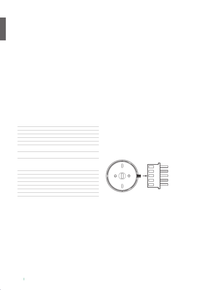
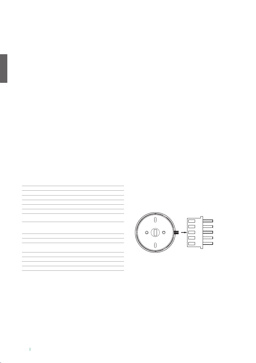
SCHEMA DI COLLEGAMENTO
Il rilevatore viene fornito con un cablaggio esterno
predisposto in fabbrica. Il collegamento deve essere
eseguito in base ai colori di identificazione. Di seguito
il significato del colore dei fili: Il rosso indica il polo
positivo dell'alimentazione, il nero indica il polo
negativo dell'alimentazione, il bianco indica il morsetto
comune dell'uscita di allarme, il giallo indica il contatto
normalmente aperto (NA) dell'uscita di allarme, l'arancione
indica il contatto normalmente chiuso (NC) dell'uscita di
allarme, come indicato nel seguente schema:
ARANCIONE: NC
GIALLO: NA
BIANCO: COM
NERO: GND
ROSSO: VCC
DESCRIZIONE DELLO STATO DEGLI INDICATORI E
DEL CICALINO
• Se non alimentato, l'indicatore luminoso è spento.
• Autotest di accensione: Le spie di colore rosso,
verde e giallo lampeggiano lentamente.
• Stato di allarme: la spia rossa lampeggia
rapidamente e il cicalino emette un segnale
acustico di allarme.
• Guasto: Se il sensore è danneggiato, la spia gialla
lampeggia lentamente e il cicalino emette un
singolo segnale acustico per 2 secondi.
• Sottotensione: La spia rossa lampeggia
lentamente e il cicalino emette un singolo segnale
acustico per 10 secondi.
• Stato normale: la spia verde è sempre accesa.

IT
4
6. Risoluzione dei problemi del
prodotto
Dopo l'accensione del dispositivo, l'indicatore non si
attiva.
Assenza di
alimentazione
Controllare il corretto collegamento
dell'alimentazione e il percorso
dei cavi.
Collegamento errato
dell'alimentazione
Controllare se i poli positivo e
negativo dell'alimentazione sono
collegati in modo errato.
Tensione di
alimentazione errata
Verificare che la tensione di
alimentazione rientri nell'intervallo
di alimentazione normale
del rilevatore; la tensione di
alimentazione normale del rilevatore
è compresa tra 10 e 24 Vcc.
L'alimentazione è a
corrente alternata
(CA) anziché a
corrente continua
(CC).
Verificare se l'alimentatore collegato
è un alimentatore a corrente
continua (CC); in caso contrario,
sostituirlo.
Auto-verifica non completata dopo l'accensione
La tensione di
alimentazione è
troppo bassa
È necessario sostituire
l'alimentazione
Il cicalino non emette un segnale acustico o il volume è
basso dopo l'allarme
Il cicalino è rotto o
non c'è corrente
Verificare se la spia rossa è
accesa durante l'allarme; se è
accesa, significa che è presente
un'anomalia del cicalino, se la spia
è spenta, significa che il rilevatore
non è alimentato.
Dopo l'accensione, la spia gialla lampeggia lentamente
e il cicalino emette un singolo segnale acustico per 2
secondi.
Anomalia del
sensore o eccessiva
sporcizia del
rilevatore
Innanzitutto, è necessario verificare
se il rilevatore è unto o se il sensore
è eccessivamente sporco. Se il
problema persiste dopo la pulizia,
significa che il sensore è rotto.
La spia rossa lampeggia lentamente dopo l'accensione
e il cicalino emette un segnale acustico ogni 10 secondi.
La tensione di
alimentazione è
troppo bassa
È necessario sostituire
l'alimentatore
Dopo un certo periodo di tempo, la spia rossa
lampeggia lentamente e il cicalino emette un segnale
acustico ogni 10 secondi.
La tensione di
alimentazione è
troppo bassa
Verificare se la tensione di
alimentazione è inferiore
all'intervallo di tensione di
funzionamento del rilevatore; se
l'alimentazione è normale, significa
che il rilevatore è rotto.
Il cicalino continua a emettere un segnale acustico e la
spia rossa lampeggia rapidamente.
Presenza di una
fuga di gas o di fumi
che penetrano nel
rilevatore.
Eliminare la fuga di gas e assicurarsi
che i fumi o altri gas non penetrino
nel rilevatore.
7. Nota
1. Non installare il rilevatore in luoghi in cui siano
presenti temperature elevate, umidità elevata,
fumi e polvere e mantenere pulito l'ambiente
circostante.
2. Evitare di installare il rilevatore in prossimità di
luoghi in cui sono presenti vernici, solventi e altri
elementi che producono sospensioni colloidali,
per non compromettere il normale funzionamento
del rilevatore.
3. Questo prodotto è un rilevatore di gas
combustibili. Quando viene rilevata una fuga
di gas combustibile, il dispositivo è in grado di
emettere un allarme acustico e visivo, ma non è
in grado di spegnere l'incendio. Si declina ogni
responsabilità legale per gli incendi e gli eventuali
danni materiali causati dalla fuga di gas.
8. Manutenzione del prodotto
1. Dopo aver installato e utilizzato il rilevatore,
è necessario premere il pulsante di prova
del rilevatore per provarlo ogni mese. Se si
riscontra un guasto (ad esempio, se, premendo
a lungo il pulsante di prova, il cicalino non
emette un segnale acustico e la spia luminosa
non si accende), è necessario provvedere
tempestivamente.
2. Dopo l'installazione, il rilevatore deve essere
mantenuto in modo adeguato eettuandone
periodicamente la pulizia per rimuovere la
polvere, la sporcizia ed eventuali residui oleosi
intorno ai fori di ingresso del gas, inoltre è
necessario adottare opportune misure anti
umidità e anticorrosione per prolungarne la
durata.
3. In caso di guasto del rilevatore o di altri problemi,
non smontare il rilevatore autonomamente
per eettuarne la manutenzione. Scollegare
l'alimentazione e contattare il rivenditore locale
per la manutenzione.
4. Quando il rilevatore emette un allarme nel caso
di fughe di gas, è necessario interrompere
immediatamente tutte le sorgenti di alimentazione
e spegnere la sorgente di gas per evitare incidenti
come incendi o esplosioni e perdite maggiori per
gli utenti.

EN
5
1. Product Profile
The combustible gas detector adopts a high-stability
semiconductor sensor, which has the characteristics
of high stability and small sensitivity drift. The product
adopts the ceiling installation method, which is simple
to install and convenient to connect. It is widely
used in homes, hotels, apartments and other places
where flammable gas leaks for safety monitoring. It
can detect natural gas, liquefied petroleum gas and
artificial coal gas.
2. Working Principle
When the detector detects the leakage of
combustible gas in the environment and reaches the
alarm concentration set by the detector, the red LED
flashes, make an alarm sound, and output an alarm
signal. When the concentration of combustible gas
in the environment drops below the set threshold,
the detector automatically returns to normal working
conditions.
3. Diagram
See the picture 1 on page 2.
4. Product Parameters
Operating Voltage DC10V~24V
Static Current ≤100mA
Alarm Current ≤160mA
Test Time 1 minute
Alarm Concentration 7%LEL (deviation:3%LEL)
Sensor High stability semiconductor sensor
Alarm Method The alarm indicator blinks and the
buzzer will beep
Reset Method When the combustible gas
concentration is lower than the alarm
concentration, automatic reset
Alarm Sound ≥70db
Alarm output NO/NC optional
Environmental Temperature 10 °C~+50 °C
Installation Method Ceiling
Relay Type DC24V 2A, AC110V 2A
Relative Humidity ≤95%, No condensation
Dimensions 95×35mm
5. Product Installation, Wiring and
Status Description
INSTALLATION PRECAUTIONS
1. First determine whether the gas to be detected is
heavier or lighter than air. Gases heavier than air:
liquefied petroleum gas, etc.; Gases lighter than
air: natural gas, artificial coal gas, biogas, etc.
2. Choose to install the detector in a suitable place
according to the weight of the gas.
When detecting gas heavier than air: install it
0.3-1.0 meters above the ground, 1.5 meters
from the gas source radius.
When detecting gas lighter than air: install
it 0.3-1.0 meters below the ceiling and 1.5
meters from the air source radius. (See the
picture 2 on page 2).
3. When installing at home, it should be noted
that the installation location should not be too
close to the gas stove to avoid the detector
being flooded by the stove flame; it cannot be
installed in a place with large oil smoke, so as
to avoid false alarms or cause the detector’s air
intake not smooth, which aects the detection
sensitivity; it cannot be installed on the exhaust
fan, the side of doors and windows, and the
bathroom where there is large moisture.
4. Wire correctly according to the diagram, and
all wiring installation must comply with national
and local eective regulations and standards.
Inappropriate connection will cause abnormal
alarm in case of gas leakage.
5. Fix the detector bracket on the wall with
mounting screws and hang the detector.
WIRING DIAGRAM
The detector comes with external wiring output when
leaving the factory. When wiring, it needs to be wired
according to the color identification. The wire color
function definition: red is the positive pole of the
power supply, black is the negative pole of the power
supply, white is the alarm output common terminal,
and yellow is the alarm output normally open (NO),
Orange is the alarm output normally closed (NC). As
shown below:
ORANGE: NC
YELLOW: NO
WHITE: COM
BLACK: GND
RED: VCC
INDICATOR AND BUZZER STATUS DESCRIPTION
• When the power is off, the indicator light is o
• Power-on self-test: Red, green, and yellow lights
flash slowly respectively.
• Alarm status: the red light flashes quickly, and the
buzzer sounds
• Fault: Sensor is damaged, the yellow light flashes
slowly, and the buzzer sounds once for 2 seconds.
• Under voltage: The red light flashes slowly, and
the buzzer sounds once for 10 seconds.
• Normal state: the green light is always on.

EN
6. Product Troubleshooting
After power on, the indicator does not light up
No power Check whether the power supply
and the route are well connected
Wrong connection of
power supply
Check whether the positive and
negative poles of the power supply
are connected incorrectly
Incorrect power
supply voltage
Confirm whether the power supply
voltage is within the normal power
supply range of the detector,
the normal power supply of the
detector is DC10~24V
The access power is
alternating current
(AC) instead of direct
current (DC)
Confirm whether the connected
power supply is a direct current
(DC) power supply, if not, please
replace it
Self-check failed after power-on
Power supply voltage
is too low
Need to replace the power supply
The buzzer does not sound or the volume is low after
the alarm
The buzzer is broken
or there is no power
Confirm whether the red light is on
when alarming, if it is on, it means
the detector buzzer is abnormal,
if the light is o, it means that the
detector is not powered on
After power-on, the yellow light flashes slowly and the
buzzer sounds once for 2 seconds
Sensor fault or
detector is too dirty
First rule out whether the detector
is oily or the detector sensor is too
dirty. If the problem persists after
cleaning, it means the sensor is
broken
The red light flashes slowly after power on, and the
buzzer sounds every 10 seconds
Power supply voltage
is too low
Need to replace the power supply
After a period of time, the red light flashes slowly and
the buzzer sounds every 10 seconds
Power supply voltage
is too low
Confirm whether the power supply
voltage is lower than the detector
working voltage range, if the power
supply is normal, it means the
detector is broken
The buzzer keeps on and the red light flashes quickly
There is a gas leak or
oily smoke entering
the detector
Eliminate gas leakage and ensure
that no oily smoke or other gas
enters the detector
7. Notice
1. Please do not install the detector in places with
high temperature, high humidity, oily smoke, and
dust, and keep the air environment around the
detector clean.
2. Avoid installing the detector near a place where
there are a lot of paint, thinner and other items
that produce colloidal suspension, so as not to
aect the normal monitoring of the detector.
3. This product is a combustible gas detector.
When it encounters a combustible gas leak, it
can give an audible and visual alarm but cannot
extinguish the fire. We do not accept any legal
responsibility for the fire and any property loss
caused by the gas leak.
8. Product Maintenance
1. After the detector is installed and used, you
need to press the detector test button to test the
detector every month. If a fault is found (such as
long pressing the test button, the buzzer does
not sound and the indicator light does not light),
it should be checked in time.
2. After the detector is installed, it should be
kept properly and corresponding dust-proof,
moisture-proof and anti-corrosion measures
should be taken to extend the service life of the
detector.
3. In the event of a detector fault or other
problems, do not disassemble the detector
privately for maintenance. Please disconnect the
power supply and contact your local dealer for
maintenance.
4. When encountering a gas leak detector alarm,
all power sources should be cut o immediately,
and the gas source should be turned o to avoid
accidents such as fire or explosion, and bring
greater losses to users.
www.comelitgroup.com
Via Don Arrigoni, 5 - 24020 Rovetta (BG) - Italy
1ª edizione 06/2022
cod. 2G40002981
CERTIFIED MANAGEMENT SYSTEMS
Table of contents
Languages:
Other Comelit Gas Detector manuals