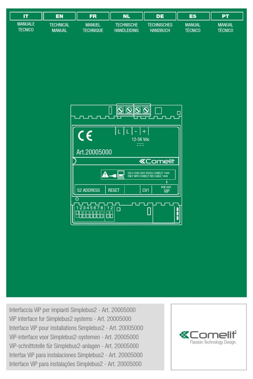
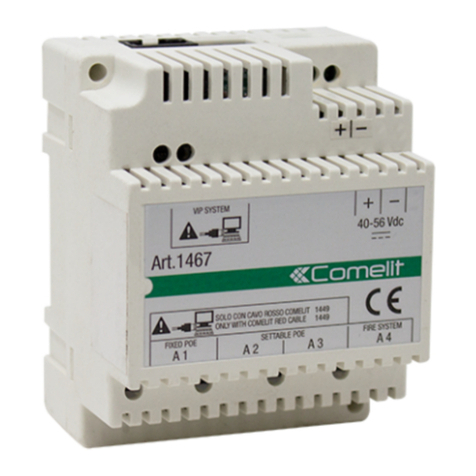
Comelit 1469 User manual

IT
MANUALE
TECNICO
EN
TECHNICAL
MANUAL
FR
MANUEL
TECHNIQUE
NL
TECHNISCHE
HANDLEIDING
DE
TECHNISCHES
HANDBUCH
ES
MANUAL
TÉCNICO
PT
MANUAL
TÉCNICO
Passion.Technology.Design.
Art. 1469
FREE DOWNLOAD
MYCOMELIT, L'APP PER IL PROFESSIONISTA
MYCOMELIT: THE APP FOR PROFESSIONALS
MYCOMELIT, L'APPLI POUR LES PROFESSIONNELS
MYCOMELIT DE APP VOOR DE PROFESSIONAL
MYCOMELIT DIE PROFI-APP
MYCOMELIT, LA APP DEL PROFESIONAL
MYCOMELIT: A APLICAÇÃO PARA O PROFISSIONAL
IT
EN
FR
NL
DE
ES
PT
Interfaccia Simplebus per base impianto ViP
Simplebus interface for ViP system base
Interface Simplebus pour base système ViP
Interface Simplebus voor basis ViP-Systeem
Simplebus-Schnittstelle Für ViP-Anlagen
Interfaz Simplebus para base instalación ViP
Interface Simplebus para base sistema ViP

32
Avvertenze
• Questo prodotto Comelit è progettato e realizzato con lo scopo di essere utilizzato nella realizzazione di impianti per
comunicazione audio e video in edifici residenziali, commerciali, industriali e in edifici pubblici o ad uso pubblico.
• Tutte le attività connesse all’installazione dei prodotti Comelit devono essere realizzate da personale tecnicamente
qualificato, seguendo attentamente le indicazioni di manuali / istruzioni dei prodotti stessi.
• Togliere l’alimentazione prima di effettuare qualsiasi operazione.
• Utilizzare conduttori con sezione adeguata in funzione delle distanze, rispettando le indicazioni riportate nel manuale di
sistema.
• Si consiglia di non posare i conduttori per l’impianto nella stessa tubazione dove transitano i cavi di potenza (230V o
superiori).
• Per l’utilizzo sicuro dei prodotti Comelit è necessario: seguire con attenzione le indicazioni di manuali e istruzioni; curare che
l’impianto realizzato con i prodotti Comelit non sia manomesso / danneggiato.
• I prodotti Comelit non prevedono interventi di manutenzione ad eccezione delle normali operazioni di pulizia, da effettuarsi
comunque secondo quanto indicato in manuali / istruzioni. Eventuali riparazioni devono essere effettuate: per i prodotti,
esclusivamente da Comelit Group S.p.A., per gli impianti, da personale tecnicamente qualificato.
• Comelit Group S.p.A. non assume alcuna responsabilità per usi differenti da quello previsto e mancato rispetto di indicazioni
ed avvertenze presenti in questo manuale. Comelit Group S.p.A. si riserva comunque il diritto di modificare in qualsiasi
momento e senza preavviso quanto descritto nel presente manuale.
Warning
• This Comelit product was designed for use in the creation of audio and video communication systems in residential,
commercial or industrial settings and in public buildings or buildings used by the public.
• All activities connected to the installation of Comelit products must be carried out by qualified technical personnel, with
careful observation of the indications provided in the manuals / instruction sheets supplied with those products.
• Cut off the power supply before carrying out any maintenance procedures.
• Use wires with a cross-section suited to the distances involved, observing the instructions provided in the system manual.
• We advise against running the system wires through the same duct as the power cables (230V or higher).
• To ensure Comelit products are used safely: carefully observe the indications provided in the manuals / instruction sheets
and make sure the system created using Comelit products has not been tampered with / damaged.
• Comelit products do not require maintenance aside from routine cleaning, which should be carried out in accordance
with the indications provided in the manuals / instruction sheets. Any repair work must be carried out: for the products
themselves, exclusively by Comelit Group S.p.A., for systems, by qualified technical personnel.
• Comelit Group S.p.A. does not assume any responsibility for: any usage other than the intended use; non-observance of the
indications and warnings contained in this manual / instruction sheet. Comelit Group S.p.A. nonetheless reserves the right
to change the information provided in this manual at any time and without prior notice.
Avertissements
• Ce produit Comelit a été conçu et réalisé pour être utilisé dans la réalisation d'installations de communication audio et vidéo
dans des bâtiments résidentiels, commerciaux, industriels et publics ou à usage public.
• Toutes les opérations liées à l'installation des produits Comelit sont réservées à des techniciens qualifiés qui devront suivre
attentivement les consignes des Manuels / Instructions desdits produits.
• Couper l'alimentation avant d'effectuer toute opération.
• Utiliser des conducteurs d'une section adéquate en fonction des distances et en respectant les explications contenues dans
le manuel du système.
• Il est conseillé de ne pas poser les conducteurs destinés à l’installation dans la canalisation destinée aux câbles de puissance
(230 V ou plus).
• Pour utiliser les produits Comelit en toute sécurité : suivre attentivement les consignes contenues dans les Manuels /
Instructions; s'assurer que l’installation réalisée avec les produits Comelit n'est pas sabotée / endommagée.
• Les produits Comelit sont sans maintenance, exception faite pour les opérations de nettoyage qui devront être effectuées
selon les consignes contenues dans les Manuels / Instructions. Les réparations concernant : les produits, sont réservées
exclusivement à Comelit Group S.p.A., les installations, sont réservées à des techniciens qualifiés.
• Comelit Group S.p.A. ne sera pas tenue pour responsable en cas d'utilisation contraire aux indications, de non-respect des
indications et des recommandations présentes dans ce Manuel / Instructions. Comelit Group S.p.A. se réserve le droit de
modifier à tout moment et sans préavis le contenu de ce Manuel / Instructions.
Waarschuwingen
• Dit product van Comelit is ontworpen en ontwikkeld om te worden gebruikt bij de realisatie van audio- en
videocommunicatiesystemen In woningen, winkels, bedrijven en openbare gebouwen of in openbare ruimtes.
• Alle functies die zijn aangesloten op de installatie van de Comelit-producten moeten zijn uitgevoerd door gekwalificeerd
technisch personeel, volgens de aanwijzingen in de handleiding/instructies van de betreffende producten.
• Sluit de voeding af voordat u onderhoudswerkzaamheden uitvoert.
• Gebruik geleiders met een geschikte doorsnede, afhankelijk van de afstanden, volgens de aanwijzingen in de handleiding
van de installatie.
• Het is raadzaam om de kabels voor de installatie niet in dezelfde leiding te plaatsen als die waar de vermogenskabels (230v
of hoger) doorheen lopen.
• Voor een veilig gebruik van de producten Comelit is het volgende noodzakelijk: het zorgvuldig opvolgen van de aanwijzingen
in de handleiding/instructies, ervoor zorgen dat de installatie die met de Comelit-producten is uitgevoerd niet wordt
gesaboteerd / beschadigd raakt.
• De producten van Comelit hebben geen onderhoud nodig, behalve de normale reiniging, welke moet worden uitgevoerd
zoals is aangegeven in de handleiding/instructies. Eventuele reparaties moeten worden uitgevoerd voor de producten,
uitsluitend door Comelit Group S.p.A., voor de installatie, door gekwalificeerd technisch personeel.
• Comelit Group S.p.A. is niet verantwoordelijkheid voor andere toepassingen dan het beoogde gebruik, het niet in acht
nemen van de aanwijzingen en waarschuwingen in deze handleiding/instructies. Comelit Group S.p.A. behoudt zich het
recht voor om op elk moment, zonder waarschuwing vooraf, wijzigingen aan te brengen in deze handleiding/instructies.
Hinweise
• Dieses Comelit-Produktist für den Einsatz in Anlagen für Audio- und Video-Kommunikation in Wohngebäuden, Gewerbe-
und Industrieanlagen, in öffentlichen Gebäuden und für den öffentlichen Gebrauch konzipiert.
• Die Installation der Comelit-Produkte darf nur durch Fachkräfte unter genauer Befolgung der Anweisungen in den technischen
Handbüchern / den Bedienungsanleitungen erfolgen.
• Vor Eingriffen an der Anlage immer die Spannungsversorgung unterbrechen.
• Leiter mit einem für die Entfernung bemessenen Querschnitt verwenden und die im Handbuch der Anlage aufgeführten
Anweisungen einhalten.
• Es wird empfohlen, die Leiter derAnlage nella nicht in den Rohren der Leistungskabel (230 V oder höher) zu verlegen.
• Sicherer Umgang mit Comelit-Produkten: Halten Sie sich strikt an die Angaben in den technischen Handbüchern / den
Bedienungsanleitungen, Nehmen Sie keine Änderungen an der Anlage mit Comelit-Produkten vor und vermeiden Sie
Beschädigungen.
• Die Comelit-Produkte erfordern keine Wartungsarbeiten, abgesehen von der normalen Reinigung, die entsprechend den
Anweisungen in den technischen Handbüchern / den Bedienungsanleitungen auszuführen ist. Eventuelle Reparaturen dürfen
für die Produkte nur durch die Firma Comelit Group S.p.A., an der Anlage nur durch Fachkräfte ausgeführt werden.
• Comelit Group S.p.A. lehnt jede Haftung ab bei Schäden durch bestimmungsfremden Gebrauch, Missachtung der
Anweisungen und Hinweise in dem vorliegenden technischen Handbuch / den Bedienungsanleitungen. Comelit Group
S.p.A. behält sich vor, jeder Zeit und ohne Vorankündigung Änderungen an dem vorliegenden technischen Handbuch / den
Bedienungsanleitungen vorzunehmen.
Advertencias
• Este producto Comelit ha sido diseñado y realizado para usarse en instalaciones de comunicación audio y vídeo tanto en
edificios residenciales, comerciales e industriales como en edificios públicos o de uso público.
• Todos los productos Comelit deben ser instalados por personal técnicamente cualificado, siguiendo con atención las
indicaciones de los manuales proporcionados con cada producto.
• Antes de efectuar cualquier operación hay que cortar la alimentación.
• Utilizar conductores de sección adecuada teniendo en cuenta las distancias y respetando las instrucciones del manual de
sistema.
• Se aconseja no colocar los conductores de la instalación en el mismo conducto eléctrico por donde pasan los cables de
potencia (230 V o superiores).
• Para el uso seguro de los productos Comelit, es necesario seguir con atención las indicaciones de los manuales / las
instrucciones e garantizar que la instalación realizada con los productos Comelit no pueda ser manipulada ni dañada.
• Los productos Comelit no prevén intervenciones de mantenimiento, salvo las normales operaciones de limpieza, que se
deben efectuar siempre según lo indicado en los manuales / las instrucciones. Las reparaciones deben ser efectuadas:
exclusivamente por Comelit Group S.p.A. cuando afecten a productos, por personal técnicamente cualificado cuando
afecten a instalaciones.
• Comelit Group S.p.A. quedará libre de cualquier responsabilidad en caso de usos diferentes a los previstos e incumplimiento
de las indicaciones y advertencias proporcionadas en el manual / las instrucciones. Comelit Group S.p.A. se reserva
siempre el derecho de modificar en cualquier momento y sin preaviso el manual / las instrucciones.
Avisos
• Este produto Comelit foi concebido e realizado com o intuito de ser utilizado na realização de instalações para comunicação
áudio e vídeo em edifícios residenciais, comerciais, industriais, públicos ou de utilização pública.
• Todas as actividades relacionadas com a instalação de produtos Comelit devem ser realizadas por pessoal tecnicamente
qualificado, seguindo atentamente as indicações dos manuais/instruções dos respectivos produtos.
• Cortar a alimentação eléctrica antes de realizar qualquer tipo de operação.
• Utilizar condutores de secção adequada em função das distâncias e respeitando as indicações no manual do sistema.
• Recomenda-se não colocar condutores para a instalação nas mesmas condutas onde se encontram os cabos de energia
(230 V ou superior).
• Para a utilização segura dos produtos Comelit é necessário: Seguir com atenção as indicações dos manuais/instruções,
Certificar-se de que a instalação realizada com produtos Comelit não é adulterada/danificada.
• Os produtos Comelit não requerem intervenções de manutenção além das normais operações de limpeza, que devem
ser realizadas segundo as indicações nos manuais/instruções. Eventuais reparações devem ser realizadas: no caso de
produtos, exclusivamente pela Comelit Group S.p.A., no caso de instalações, por pessoal tecnicamente qualificado.
• Comelit Group S.p.A. não assume qualquer responsabilidade por utilizações diferentes das previstas e desrespeito pelas
indicações e avisos presentes neste manual/instruções. Comelit Group S.p.A. reserva-se o direito de modificar a qualquer
momento e sem aviso prévio o descrito no presente manual/instruções.
IT
IT
L’art. 1469 è un’interfaccia per la gestione di
configurazioni ibride dell'impianto videocitofonico con
citofoni e videocitofoni in tecnologia 2 fili (SimpleBus
e SimpleBus2) e dispositivi in tecnologia IP per la
struttura di base dell'impianto (posti esterni, centralini,
moduli attuatori, call log, etc).
I citofoni e videocitofoni 2 fili potranno ricevere
le chiamate dal posto esterno ViP, eettuare
chiamate e inoltrare comandi verso i dispositivi ViP
(autoaccensione, chiamata al centralino principale
e/o secondario, comando attuatori, visualizzazione
telecamera ViP, visualizzazione telecamera RTSP,
etc.).
1.
2.
5.
4.
3.
6.
Fig. 1
Fig. 1
1. Morsetti LL
Connessione alla linea Simplebus1 o Simplebus2
2. Jumper per la selezione del bus utilizzato
• Simplebus1
• Simplebus2
• Selezione automatica del bus
3. DIP-Switches per eettuare le procedure di
riavvio e ripristino parametri
4. + - Morsetti di alimentazione 33 VDC
5. Porta Ethernet RJ45
6. LED di segnalazione connettività Ethernet
LED
Spento Nessuna connessione Ethernet
Lampeggiante Connessione Ethernet presente
comunicazione attiva
Acceso
fisso Connessione Ethernet presente
nessuna comunicazione attiva
Caratteristiche principali
• Tutti i dispositivi ViP sono compatibili con l’art. 1469
• È possibile controllare l’art. 1256 solo nella
montante Simplebus.
• Non è possibile eettuare una chiamata
itercomunicante tra due montanti distinte
Simplebus.
• Gestione chiamate audio e audiovideo da/e verso il
mondo Simplebus.
• Conversione e mappatura di messaggi da
Simplebus a ViP e viceversa.
• I centralini possono essere solo ViP.
• Non è possibile installare un posto esterno
secondario Simplebus.
Caratteristiche tecniche
Tensione di alimentazione
morsetti + - 33 VDC
Assorbimento in stand-by
ingresso DC 95 mA - 3,1 W
Assorbimento max. LL con
1210A (Simplebus2)
100 mA 3,2 W
125 mA 4 W
Assorbimento in stand-by LL
con 1210A (Simplebus2) 50 mA 1,6 W
Assorbimento max.
configurazione Simplebus1
120 mA 4 W
130 mA 4.3 W
Assorbimento in stand-by
configurazione Simplebus 1 100 mA 3,3 W
N° massimo di posti interni
audio Simplebus1 100
N° massimo di posti interni
video Simplebus2 100
Distanza di collegamento Ethernet
con art. 1440 porta IN 100 m
Distanza di collegamento Ethernet
con art. 1440 porta OUT 150 m
Porta ethernet 10/100 Mbps
Temperatura di funzionamento (°C) -5 ÷ +50
Umidità di funzionamento
(RH max) 95%
Dimensioni (mm) 90x70x59
(4 moduli DIN)
Programmazione tramite ViP Manager
Tutte le configurazioni dell’art. 1469 possono essere
eettuate tramite PC e software di configurazione
ViP Manager, scaricabile gratuitamente dal sito
pro.comelitgroup.com
Per la connessione del PC alla rete ViP tramite
art. 1440 utilizzare il cavo rosso Comelit art.
1449.
Dispositivi Simplebus compatibili
6601W VIDEOCITOFONO ICONA BIANCO. SISTEMA
SIMPLEBUS2
6701W VIDEOCITOFONO MINI CORNETTA.
BIANCO. SISTEMA SBTOP
6721W VIDEOCITOFONO MINI VIVAVOCE BIANCO.
SISTEMA SBTOP.
6741W VIDEOCITOFONO MINI VIVAVOCE WI-FI.
SISTEMA 2 FILI
6801 VIDEOCITOFONO 7" SERIE MAXI. SISTEMA
SBC
20034801 TOUCH SCREEN PLANUX MANAGER 3,5''
SUPERVISORE BIANCO
1256 ACCESSORIO RELÈ ATTUATORE DIGITALE
SISTEMA SIMPLEBUS
1412 MORSETTO DI COLLEGAMENTO 1IN-4OUT.
SISTEMA SBC
1414 MODULO DERIVATORE DI MONTANTE
SISTEMA SIMPLEBUS
1214/2C MORSETTO DI COLLEGAMENTO
SIMPLEBUS 2 E SIMPLEBUS COLOR
1214/2G MORSETTO DI DERIVAZIONE MONITOR
GENIUS
1215 MORSETTO DI COLLEGAMENTO
SIMPLEBUS2/COLOR/KIT
1229A ACCESSORIO SUONERIA
SUPPLEMENTARE PER SISTEMA
SIMPLEBUS2
2628 CITOFONO ELEGANCE SERIE STYLE
BIANCO. SISTEMA SIMPLEBUS2
2638 CITOFONO BASIC SERIE STYLE.SISTEMA
SIMPLEBUS2
2619 CITOFONO VERSIONE ELEGANCE
SIMPLEBUS TOP INTERCOMUNICANTE
6228W CITOFONO VIVAVOCE SIST. SIMPLEBUS/
KIT SERIE EASYCOM - BIANCO
6750W CITOFONO MINI VIVAVOCE E BM. SISTEMA
A/V S2
2708W CITOFONO MINI 2 PULSANTI, SIMPLEBUS
AUDIO
2738W CITOFONO CON 2 PULSANTI PER
SIMPLEBUS TOP A/V. SERIE MINI
2719W CITOFONO CON 5 PULSANTI PER
SIMPLEBUS TOP A/V. SERIE MINI
Riavvio con parametri di rete predefiniti
Questa procedura consente al modulo di riavviarsi
con i parametri di rete di default.
In caso di ulteriore riavvio il modulo:
• ripristinerà i parametri della precedente
configurazione qualora non fosse stata eseguita
nessuna modifica da parte dell'utente;
• in caso di modifica dei parametri tramite ViP
Manger, il modulo si avvierà con i nuovi parametri
di rete.
}DIP-Switches in posizione OFF
1. Togliere l'alimentazione dal dispositivo
2. Impostare il DIP 1 in posizione ON
3. Alimentare il dispositivo
4. Attendere circa 20-40 sec. fino a quando i LED
lampeggeranno lentamente in modo alternato (1
sec. rosso / 1 sec. verde)
5. Riportare il DIP1 in posizione OFF
»Il LED verde lampeggerà per 5 sec.
»Il dispositivo si avvierà con i parametri di rete di
default.
• A un successivo riavvio il dispositivo recupererà i
paramettri salvati.
Ripristino impostazioni di fabbrica
Questa procedura consente di ripristinare tutti i
parametri ai valori di fabbrica e di cancellare tutte le
configurazioni del dispositivo.
}DIP-Switches in posizione OFF
1. Togliere l'alimentazione dal dispositivo
2. Impostare tutti i DIP in posizione ON
3. Alimentare il dispositivo
4. Attendere circa 20-40 sec. fino a quando i LED
lampeggeranno velocemente in modo alternato
(0.1 sec. rosso /0.1 sec. verde)
5. Riportare i DIP-Switches in posizione OFF
›› Il LED rosso lampeggerà per 5 sec.
›› Il dispositivo si riavvia.
54

Art. 1469 is an interface for the management of
hybrid video entry phone system configurations with
door-entry phones and door entry monitors using
2-wire technology (SimpleBus and SimpleBus2) and
devices using IP technology for the basic system
structure (external units, switchboards, actuator
modules, call logs, etc.).
The 2-wire door-entry phones and door entry monitors
can receive calls from the ViP external unit and forward
commands to ViP devices (self activation, call to main
and/or secondary switchboard, actuator control, view
ViP cameras, view RTSP cameras, etc.).
1.
2.
5.
4.
3.
6.
Fig. 1
Fig. 1
1. LL terminals
Connection to the Simplebus1 or Simplebus2
line
2. Jumper for selecting the bus used
• Simplebus1
• Simplebus2
• Automatic bus selection
3. DIP-switches for reboot with predetermined
network settings and carrying out the factory
reset procedure
4. + - Power supply terminals 33 VDC
5. RJ45 Ethernet port
6. LED indicating Ethernet connection
LED
O No Ethernet connection
Flashing Ethernet connection present,
communication active
Steadily lit Ethernet connection present, no
active communication
Main features
• All ViP devices are compatible with art. 1469.
• Art. 1256 can only be controlled on the Simplebus
riser.
• An intercom call cannot be made between two
separate Simplebus risers.
• Management of audio and audio/video calls from/
to Simplebus devices.
• Conversion and mapping of messages from
Simplebus to ViP and vice-versa.
• Switchboards may be ViP only.
• A secondary Simplebus external unit cannot be
installed.
Technical specifications
+ - terminals power supply
voltage 33 VDC
DC input absorption in
standby 95 mA - 3,1 W
LL max. absorption with
1210A (Simplebus2)
100 mA 3,2 W
125 mA 4 W
LL absorption in standby with
1210A (Simplebus2) 50 mA 1,6 W
Max. absorption with
Simplebus1 configuration
120 mA 4 W
130 mA 4.3 W
Absorption in standby,
Simplebus1 configuration 100 mA 3,3 W
Maximum number of
Simplebus1 audio internal
units
100
Maximum number of
Simplebus2 video internal
units
100
Ethernet connection distance
with 1440, IN port 100 m
Ethernet connection distance
with 1440, OUT port 150 m
Ethernet port 10/100 Mbps
Operating temperature (°C) -5 to +50
Operating humidity (max. RH) 95%
Dimensions 90x70x59 mm
(4 DIN modules)
Programming via ViP Manager
All art. 1469 configurations can be implemented via
PC and ViP Manager configuration software, which is
available to download free of charge from the website
pro.comelitgroup.com
When connecting the PC to the ViP network via
art. 1440, use the red Comelit cable art. 1449.
Compatible Simplebus devices
6601W ICONA DOOR ENTRY MONITOR, WHITE.
SIMPLEBUS2 SYSTEM
6701W MINI HANDSET DOOR ENTRY MONITOR.
WHITE. SBTOP SYSTEM
6721W MINI HANDS-FREE DOOR ENTRY
MONITOR, WHITE. SBTOP SYSTEM
6741W MINI HANDS-FREE WI-FI DOOR ENTRY
MONITOR. 2-WIRE SYSTEM
6801 MAXI SERIES 7” DOOR ENTRY MONITOR.
SBC SYSTEM
20034801 PLANUX MANAGER 3.5” TOUCH-SCREEN
SYSTEM MANAGER, WHITE
1256 DIGITAL ACTUATOR RELAY ACCESSORY,
SIMPLEBUS SYSTEM
1412 1IN-4OUT CONNECTION TERMINAL. SBC
SYSTEM
1414 RISER DISTIBUTOR MODULE, SIMPLEBUS
SYSTEM
1214/2C CONNECTION TERMINAL, SIMPLEBUS 2
AND SIMPLEBUS COLOR
1214/2G GENIUS MONITOR DISTRIBUTION
TERMINAL
1215 CONNECTION TERMINAL, SIMPLEBUS2/
COLOR/KIT
1229A ADDITIONAL RINGTONE ACCESSORY FOR
SIMPLEBUS2 SYSTEM
2628 STYLE SERIES ELEGANCE DOOR-ENTRY
PHONE, WHITE. SIMPLEBUS2 SYSTEM
2638 STYLE SERIES BASIC DOOR-ENTRY
PHONE. SIMPLEBUS2 SYSTEM
2619 ELEGANCE VERSION DOOR-ENTRY
PHONE, SIMPLEBUS TOP INTERCOM
6228W HANDS-FREE DOOR-ENTRY PHONE,
SIMPLEBUS/KIT SYST., EASYCOM SERIES
- WHITE
6750W MINI HANDS-FREE DOOR-ENTRY PHONE
AND AIL. S2 A/V SYSTEM
2708W MINI DOOR-ENTRY PHONE, 2 BUTTONS,
SIMPLEBUS AUDIO
2738W DOOR-ENTRY PHONE WITH 2 BUTTONS
FOR SIMPLEBUS TOP A/V. MINI SERIES
2719W DOOR-ENTRY PHONE WITH 5 BUTTONS
FOR SIMPLEBUS TOP A/V. MINI SERIES
Reboot with predetermined network settings
This procedure is used to restart the module with the
default network parameters.
In the event of a further restart the module:
• will restore the parameters from the previous
configuration, if the user has not made any
changes;
• will start up with the new network parameters,
if the parameters have been changed using ViP
Manager.
}DIP-switches set to OFF
1. Cut o the device power supply
2. Set DIP 1 to ON
3. Restore the device power supply
4. Wait for approximately 20-40 sec., until the LEDs
flash slowly and alternately (1 sec. red / 1 sec.
green)
5. Set DIP1 back to OFF
»The green LED will flash for 5 sec.
»The device will start with the default network
settings.
• The saved parameters will be recovered at a
subsequent device restart process.
Restore factory settings
This procedure is used to restore all the parameter
values to their factory settings, and to clear all device
configurations.
}DIP-switches set to OFF
1. Cut o the device power supply
2. Set all DIP-switches to ON
3. Restore the device power supply
4. Wait for approximately 20-40 sec., until the LEDs
flash rapidly and alternately (0.1 sec. red / 0.1 sec.
green)
5. Set the DIP-switches back to OFF
›› The red LED will flash for 5 sec.
›› The device will restart.
EN
EN
76

L’art. 1469 est une interface pour la gestion de
configurations hybrides du système vidéo avec postes
audio et moniteurs vidéophoniques à technologie 2 fils
(SimpleBus et Simplebus2) et dispositifs à technologie
IP pour la structure de base du système (postes
extérieurs, standards, modules actionneurs, call log,
etc..).
Les postes audio et les moniteurs vidéophoniques 2
fils pourront recevoir les appels provenant du poste
extérieur VIP, eectuer des appels et envoyer des
commandes vers les dispositifs VIP (auto-allumage,
appel au standard principal et/ou secondaire,
commandes actionneurs, visualisation caméra VIP,
visualisation caméra RTSP, etc.).
1.
2.
5.
4.
3.
6.
Fig. 1
Fig. 1
1. Bornes LL
Connexion à la ligne Simplebus1 ou Simplebus2
2. Cavalier pour la sélection du bus utilisé
• Simplebus1
• Simplebus2
• Sélection automatique du bus
3. DIP-switches pour procéder à la réinitialisation
des paramétrages d'usine et redémarrage
4. + - Bornes d'alimentation 33 Vcc
5. Port Ethernet RJ45
6. LED de signalisation connectivité Ethernet
LED
Éteinte Aucune connexion Ethernet
Clignotante Connexion Ethernet présente
communication active
Allumé fixe Connexion Ethernet présente
aucune communication active
Caractéristiques principales
• Tous les dispositifs VIP sont compatibles avec l’art.
1469
• Il est possible de contrôler l’art. 1256 uniquement
dans la colonne montante Simplebus.
• Impossible d’eectuer un appel intercommunicant
entre deux colonnes montantes Simplebus.
• Gestion des appels audio et audio-vidéo depuis/et
vers le monde Simplebus.
• Conversion et mappage des messages depuis
Simplebus à VIP et vice versa.
• Les standards peuvent être uniquement VIP.
• Impossible d’installer un poste extérieur secondaire
Simplebus.
Caractéristiques techniques
Tension d'alimentation
bornes + - 33Vcc
Consommation au repos
entrée CC 95mA - 3,1W
Consommation maxi LL avec
1210A (Simplebus2)
100 mA 3,2 W
125 mA 4 W
Consommation au repos LL
avec 1210A (Simplebus2) 50mA 1,6W
Consommation maxi LL
configuration Simplebus1
120 mA 4 W
130 mA 4.3 W
Consommation au repos
configuration Simplebus1 100 mA 3,3 W
Nombre maximum de postes
intérieurs audio Simplebus1 100
Nombre maximum de postes
intérieurs video Simplebus2 100
Distance de connexion
Ethernet avec 1440 port IN 100 m
Distance de connexion
Ethernet avec 1440 port OUT 150 m
Port Ethernet 10/100 Mbps
Température de service (°C) -5 ÷ +50
Humidité de fonctionnement
(RH maxi) 95%
Dimensions 90x70x59 mm (4
modules DIN)
Programmation à travers VIP Manager
Toutes les configurations de l’art. 1469 peuvent
être eectuées sur ordinateur avec le logiciel de
configuration VIP Manager, à télécharger gratuitement
sur le site pro.comelitgroup.com.
Pour la connexion de l’ordinateur au réseau VIP
via l’art. 1440, utiliser le câble rouge Comelit art.
1449.
Dispositifs Simplebus compatibles
6601W MONITEUR VIDÉOPHONIQUE ICONA
BLANC. SYSTÈME SIMPLEBUS2
6701W MONITEUR VIDÉOPHONIQUE MINI AVEC
COMBINÉ. BLANC. SYSTÈME SBTOP
6721W MONITEUR VIDÉOPHONIQUE MINI MAINS
LIBRES BLANC. SYSTÈME SBTOP.
6741W MONITEUR VIDÉOPHONIQUE MINI MAINS
LIBRES WI-FI. SYSTÈME 2 FILS
6801 MONITEUR VIDÉOPHONIQUE 7" SÉRIE
MAXI. SYSTÈME SBC
20034801 MONITEUR PLANUX MANAGER BLANC 3,5"
1256 RELAIS ACTIONNEUR NUMÉRIQUE
SYSTÈME SIMPLEBUS
1412 BORNE DE CONNEXION 1ENTRÉE-
4SORTIES. SYSTÈME SBC
1414 MODULE DÉRIVATEUR DE COLONNE
MONTANTE SYSTÈME SIMPLEBUS
1214/2C BORNE DE CONNEXION SIMPLEBUS2 ET
SIMPLEBUS COLOR
1214/2G BORNE DE DÉRIVATION MONITEUR
GENIUS
1215 BORNE DE CONNEXION SIMPLEBUS2/
COLOR/KIT
1229A ACCESSOIRE SONNERIE
SUPPLÉMENTAIRE POUR SYSTÈME
SIMPLEBUS2
2628 POSTE AUDIO ELEGANCE SÉRIE STYLE
BLANC. SYSTÈME SIMPLEBUS2
2638 POSTE AUDIO BASIC SÉRIE STYLE.
SYSTÈME SIMPLEBUS2
2619 POSTE AUDIO VERSION ELEGANCE
SIMPLEBUS TOP INTERCOMMUNICANT
6228W POSTE AUDIO MAINS LIBRES SYST.
SIMPLEBUS/KIT SÉRIE EASYCOM - BLANC
6750W POSTE AUDIO MINI MAINS LIBRES ET BM.
SYSTÈME A/V S2
2708W POSTE AUDIO MINI 2 BOUTONS,
SIMPLEBUS AUDIO
2738W COMBINÉ AUDIO 2 BOUTONS POUR
SIMPLEBUS TOP A/V. SÉRIE MINI
2719W COMBINÉ AUDIO 5 BOUTONS POUR
SIMPLEBUS TOP A/V. SÉRIE MINI
Redémarrage avec paramètres de réseau
prédéfinis
Cette procédure permet au module de redémarrer
avec les paramètres de réseau prédéfinis par défaut.
En cas de redémarrage supplémentaire, le module :
• rétablira les paramètres de la configuration
précédente si l’utilisateur n’a effectué aucune
modification ;
• si les paramètres ont été modifiés en utilisant
VIP Manager, le module redémarrera avec les
nouveaux paramètres de réseau.
}DIP-Switches sur la position OFF
1. Couper l'alimentation au dispositif.
2. Régler le DIP 1 sur ON
3. Mettre le dispositif sous tension.
4. Attendre environ 20 à 40 secondes jusqu'à ce que
les leds clignotent lentement l'une après l'autre (1
seconde rouge / 1 seconde verte).
5. Remettre le DIP1 sur OFF
»La led verte clignote 5 secondes.
»Le dispositif se met en marche et fonctionne selon
les paramètres définis par défaut.
• Au redémarrage suivant, le dispositif récupèrera
les paramètres enregistrés.
Rétablissement des paramétrages d'usine
Cette procédure permet de rétablir tous les
paramètres sur les valeurs d'origine et d'effacer toutes
les configurations du dispositif.
}DIP-Switches sur la position OFF
1. Couper l'alimentation au dispositif.
2. Régler tous les DIP sur ON
3. Mettre le dispositif sous tension.
4. Attendre environ 20 à 40 secondes jusqu'à ce que
les leds clignotent rapidement l'une après l'autre
(0,1 seconde rouge / 0,1 seconde verte).
5. Remettre les DIP-Switches sur OFF
›› La led rouge clignotera 5 secondes.
›› Le dispositif se remet en marche.
FR
FR
98

Art. 1469 is een interface voor het beheer
van hybride configuraties van het video-
deurintercomsysteem met deurtelefoons en video-
deurintercoms met 2-draads technologie (Simplebus
en Simplebus2) en apparaten met IP-technologie voor
de basisstructuur van het systeem (binnentoestellen,
centrales, relaismodules, call log, enz.).
De 2-draads deurtelefoons en video-deurintercoms
kunnen de oproepen vanaf het ViP deurstation
ontvangen, oproepen uitvoeren en opdrachten
doorschakelen naar de ViP-apparaten (beeldoproep,
oproep naar hoofd- en/of secundaire centrale,
relaissturing, weergave ViP-camera's, weergave
RTSP-camera's, enz.).
1.
2.
5.
4.
3.
6.
Fig. 1
Fig. 1
1. Klemmen LL
Aansluiting op de lijn Simplebus1 of Simplebus2
2. Jumper voor het selecteren van de bus die
gebruikt wordt
• Simplebus1
• Simplebus2
• Automatische selectie van
de bus
3. DIP-switches voor het uitvoeren van de
herstelprocedure van de fabrieksinstellingen
4. + - Voedingsklemmen 33 VDC
5. Ethernet-poort RJ45
6. Signaleringsled ethernetverbinding
LED
Uit Geen ethernetverbinding
Knipperend Ethernetverbinding aanwezig audio
actief
Continu
brandend Ethernetverbinding aanwezig geen
audio actief
Belangrijkste kenmerken
• Alle ViP-apparaten zijn compatibel met art. 1469.
• Art. 1256 kan alleen worden bedient in de
stamleiding van Simplebus2.
• Er kan geen intercomoproep worden uitgevoerd
tussen twee afzonderlijke Simplebus2
stamleidingen.
• Beheer audio- en audio/video-oproepen van en
naar de Simplebus-module.
• Conversie en mapping van berichten van Simplebus
naar ViP en andersom.
• De centrales kunnen alleen ViP-centrales zijn.
• Er kan geen secundair deurstation Simplebus
worden geïnstalleerd.
Technische eigenschappen
Voedingsspanning + - klemmen 33 Vdc
Verbruik in stand-by DC ingang 95 mA - 3,1 W
Maximum verbruik LL met
1210A (Simplebus2)
100 mA 3,2 W
125 mA 4 W
Verbruik in stand-by LL met
1210A (Simplebus2) 50 mA 1,6 W
Maximum verbruik configuratie
Simplebus1
120 mA 4 W
130 mA 4.3 W
Verbruik in stand-by
configuratie Simplebus1 100 mA 3,3 W
Maximum aantal audio
binnentoestellen Simplebus1 100
Maximum aantal video
binnentoestellen Simplebus2 100
Aansluitafstand ethernet met
1440 IN-poort 100 m
Aansluitafstand ethernet met
1440 OUT-poort 150 m
Ethernet-poort 10/100 Mbps
Temperatuurbereik (°C) -5 ÷ +50
Relatieve luchtvochtigheid (RH
max) 95%
Afmetingen 90x70x59 mm (4
DIN-modules)
Programmering via ViP Manager
Alle configuraties van art. 1469 kunnen worden
uitgevoerd via de computer en de configuratiesoftware
ViP Manager, die gratis kan worden gedownload via
de site pro.comelitgroup.com.
Gebruik voor de verbinding van de computer
met het ViP-netwerk via art. 1440 de rode
Comelit-kabel art. 1449.
Compatibele Simplebus-apparaten
6601W ICONA VIDEO-DEURINTERCOM, WIT.
SIMPLEBUS2
6701W MINI VIDEO-DEURINTERCOM MET HOORN,
WIT. SBTOP
6721W MINI HANDSFREE VIDEO-DEURINTERCOM,
WIT. SBTOP.
6741W MINI HANDSFREE VIDEO-DEURINTERCOM
WI-FI. 2-DRAADSSYSTEEM
6801 MAXI 7" VIDEO-DEURINTERCOM. SBC-
SYSTEEM
20034801 PLANUX MANAGER 3,5'' TOUCHSCREEN
BEDIENINGSUNIT, WIT
1256 ACCESSOIRE DIGITAAL RELAIS
SIMPLEBUS-SYSTEEM
1412 AANSLUITKLEM 1IN-4OUT. SBC-SYSTEEM
1414 MODULE STAMLEIDINGSVERDELER
SIMPLEBUS-SYSTEEM
1214/2C AANSLUITKLEM SIMPLEBUS 2 EN
SIMPLEBUS COLOR
1214/2G AFTAKBLOKJE MONITOR GENIUS
1215 AANSLUITKLEM SIMPLEBUS2/COLOR/KIT
1229A ACCESSOIRE EXTRA BEL VOOR SYSTEEM
SIMPLEBUS2
2628 STYLE ELEGANCE DEURTELEFOON, WIT.
SIMPLEBUS2
2638 STYLE BASIC DEURTELEFOON.
SIMPLEBUS2
2619 STYLE ELEGANCE DEURTELEFOON.
SIMPLEBUS TOP
6228W EASYCOM HANDSFREE DEURINTERCOM.
WIT. SIMPLEBUS/KIT
6750W MINI HANDSFREE DEURTELEFOON EN BM.
A/V-SYSTEEM S2
2708W MINI DEURTELEFOON 2 DRUKKNOPPEN,
SIMPLEBUS AUDIO
2738W DEURINTERCOM MET 2 DRUKKNOPPEN
VOOR SIMPLEBUS TOP A/V. SERIE MINI
2719W DEURINTERCOM MET 5 DRUKKNOPPEN
VOOR SIMPLEBUS TOP A/V. SERIE MINI
Start opnieuw met de standaard
netwerkparameters
Via deze procedure kan de module opnieuw starten
met de standaard netwerkparameters.
Bij een volgende herstart van de module:
• worden de parameters van de vorige configuratie
hersteld indien de gebruiker geen wijzigingen heeft
aangebracht;
• indien de parameters zijn gewijzigd via ViP
Manager, zal de module starten met de nieuwe
netwerkparameters.
}DIP-switches in positie OFF
1. Haal de spanning van het apparaat
2. Zet DIP 1 in positie ON
3. Geef het apparaat spanning
4. Wacht circa 20-40 sec. totdat de leds langzaam en
afwisselend knipperen (1 sec. rood / 1 sec. groen)
5. Zet DIP1 in positie OFF
»De groene led knippert 5 sec.
»Het toestel start op met de standaard
netwerkparameters.
• Wanneer het toestel weer opnieuw wordt gestart,
worden de opgeslagen parameters opgehaald.
Fabrieksinstellingen herstellen
Via deze procedure kunnen alle parameters worden
teruggezet op de fabriekswaarden en kunnen alle
configuraties van het toestel worden gewist.
}DIP-switches in positie OFF
1. Haal de spanning van het apparaat
2. Zet alle DIP-switches in positie ON
3. Geef het apparaat spanning
4. Wacht circa 20-40 sec. totdat de leds snel en
afwisselend knipperen (0,1 sec. rood / 0,1 sec.
groen)
5. Zet de DIP-Switches in positie OFF
›› De rode led zal 5 sec. knipperen.
›› Het apparaat start opnieuw op.
NL
NL
1110

Art. 1469 ist eine Schnittstelle zur Verwaltung
hybrider Konfigurationen der Video-Türsprechanlage
mit Innensprechstellen und Videosprechstellen in
2-Draht-Technologie (SimpleBus und SimpleBus2) und
Geräten der IP-Technologie für die Grundstruktur der
Anlage (Außensprechstellen, Zentralen, Relaismodule,
Call Log etc).
Die2-Draht-InnensprechstellenundVideosprechstellen
können Rufe von der ViP-Außensprechstelle
empfangen, Rufe ausführen und Befehle an ViP-
Geräte weiterleiten (Selbsteinschaltung, Ruf an Haupt-
und/oder Nebenzentrale, Relaissteuerung, Anzeige
ViP-Kamera, Anzeige RTSP-Kamera etc.).
1.
2.
5.
4.
3.
6.
Fig. 1
Abb. 1
1. Klemmen LL
Anschluss an Leitung Simplebus1 oder
Simplebus2
2. Jumper zur Auswahl der verwendeten Busleitung
• Simplebus1
• Simplebus2
• Automatische Auswahl der
Busleitung
3. DIP-switches zum Zurücksetzen auf die
Werkseinstellung und Neustart mit vorgegebenen
Netzwerkparametern
4. + - Versorgungsklemmen 33 VDC
5. Ethernet-Port RJ45
6. LED-Anzeige Ethernet-Konnektivität
LED
Aus Keine Ethernet-Verbindung
Blinkend Ethernet-Verbindung vorhanden,
aktive Kommunikation
Dauerleuchten Ethernet-Verbindung vorhanden,
keine aktive Kommunikation
Haupteigenschaften
• Alle ViP-Geräte sind kompatibel mit Art. 1469
• Art. 1256 kann nur in der Simplebus-Steigleitung
gesteuert werden.
• Es kann kein Internruf zwischen zwei verschiedenen
Simplebus-Steigleitungen ausgeführt werden.
• Verwaltung von Audio- und Audio/Video-Rufen
vom/zum Simplebus-System.
• Konvertierung und Mapping von Meldungen von
Simplebus zu ViP und umgekehrt.
• Die Zentralen können nur ViP sein.
• Es kann keine zusätzliche Simplebus
Außensprechstelle installiert werden.
Technische Daten
Spannungsversorgung
Klemmen + - 33 VDC
Stromaufnahme in Standby
Eingang DC 95 mA - 3,1 W
Max. Stromaufnahme LL
mit 1210A (Simplebus2)
100 mA 3,2 W
125 mA 4 W
Stromaufnahme in Standby
LL mit 1210A (Simplebus2) 50 mA 1,6 W
Max. Stromaufnahme
Konfiguration Simplebus1
120 mA 4 W
130 mA 4.3 W
Stromaufnahme in Standby
Konfiguration Simplebus1 100 mA 3,3 W
Max. Anzahl Audio
Innensprechstellen
Simplebus1
100
Max. Anzahl Video
Innensprechstellen
Simplebus2
100
Ethernet max. Entfernung
mit 1440 Port IN 100 m
Ethernet max. Entfernung
mit 1440 Port OUT 150 m
Ethernet-Port 10/100 Mbps
Betriebstemperatur (°C) -5 ÷ +50
Betriebsfeuchtigkeit (RH
max.) 95%
Abmessungen 90x70x59 mm
(4 DIN-Module)
Programmierung über ViP Manager
Alle Konfigurationen des Art. 1469 können mit PC
und Konfigurationssoftware ViP Manager ausgeführt
werden, die auf der Website pro.comelitgroup.com
zum kostenlosen Download zur Verfügung steht
Zum Anschluss des PCs an das ViP-Netzwerk
über Art. 1440 das rote Comelit Kabel Art. 1449
verwenden.
Kompatible Simplebus-Geräte
6601W VIDEOSPRECHSTELLE ICONA WEISS.
SYSTEM SIMPLEBUS2
6701W VIDEOSPRECHSTELLE MINI MIT HÖRER.
WEISS. SYSTEM SBTOP
6721W VIDEOSPRECHSTELLE MINI MIT
FREISPRECHFUNKTION WEISS. SYSTEM
SBTOP.
6741W WLAN VIDEOSPRECHSTELLE MINI MIT
FREISPRECHFUNKTION. 2-DRAHT-SYSTEM
6801 VIDEOSPRECHSTELLE 7" SERIE MAXI.
SYSTEM SBC
20034801 TOUCHSCREEN PLANUX MANAGER 3,5'‘
SUPERVISOR WEISS
1256 ZUBEHÖR DIGITALES RELAIS-
AKTORMODUL SYSTEM SIMPLEBUS
1412 ANSCHLUSSKLEMME 1IN-4OUT. SYSTEM
SBC
1414 ABZWEIGMODUL FÜR STEIGLEITUNG
SYSTEM SIMPLEBUS
1214/2C ANSCHLUSSKLEMME SIMPLEBUS 2 UND
SIMPLEBUS COLOR
1214/2G ABZWEIGKLEMME MONITOR GENIUS
1215 ANSCHLUSSKLEMME SIMPLEBUS2/
COLOR/KIT
1229A ZUBEHÖR ZUSATZ-LÄUTEWERK FÜR
SYSTEM SIMPLEBUS2
2628 INNENSPRECHSTELLE ELEGANCE SERIE
STYLE WEISS. SYSTEM SIMPLEBUS2
2638 INNENSPRECHSTELLE BASIC SERIE
STYLE.SYSTEM SIMPLEBUS2
2619 INNENSPRECHSTELLE VERSION
ELEGANCE SIMPLEBUS TOP INTERCOM
6228W INNENSPRECHSTELLE MIT
FREISPRECHFUNKTION SYST. SIMPLEBUS/
KIT SERIE EASYCOM - WEISS
6750W INNENSPRECHSTELLE MINI MIT
FREISPRECHFUNKTION UND BM. SYSTEM
A/V S2
2708W INNENSPRECHSTELLE MINI 2 TASTEN,
SIMPLEBUS AUDIO
2738W INNENSPRECHSTELLE MIT 2 TASTEN FÜR
SIMPLEBUS TOP A/V. SERIE MINI
2719W INNENSPRECHSTELLE MIT 5 TASTEN FÜR
SIMPLEBUS TOP A/V. SERIE MINI
Neustart mit vorgegebenen
Netzwerkparametern
Mit diesem Verfahren können Sie das Modul mit den
Standard-Netzwerkparametern starten.
Bei einem weiteren Neustart:
• wird das Modul die Parameter der vorherigen
Konfiguration wiederherstellen, sofern der
Benutzer keine Änderungen vorgenommen hat;
• bei Parameteränderungen über ViP Manger startet
das Modul mit den neuen Netzwerkparametern.
}DIP-Schalter in Stellung OFF
1. Die Spannungsversorgung des Geräts
unterbrechen
2. Den DIP 1 in Stellung ON bringen
3. Spannungsversorgung des Geräts einschalten
4. Ca. 20-40 Sekunden warten, bis die LEDs langsam
abwechselnd blinken (1 Sek. rot / 1 Sek. grün)
5. Den DIP1 in Stellung OFF bringen
»Die grüne LED blinkt für 5 Sekunden.
»Das Gerät schaltet sich mit den Standard-
Netzparametern ein.
• Beim nächsten Neustart stellt das Gerät die
gespeicherten Parameter wieder her.
Zurücksetzen auf Werkseinstellungen
Dieses Verfahren ermöglicht, alle Parameter auf
die werksseitigen Werte zurückzusetzen und alle
Konfigurationen des Geräts zu löschen.
}DIP-Schalter in Stellung OFF
1. Die Spannungsversorgung des Geräts
unterbrechen
2. Bringen Sie alle DIP in Stellung ON
3. Spannungsversorgung des Geräts einschalten
4. Ca. 20-40 Sekunden warten, bis die LEDs schnell
abwechselnd blinken (0,1 Sek. rot / 0,1 Sek. grün)
5. Bringen Sie die DIP-Schalter in Stellung OFF
›› Die rote LED blinkt für 5 Sek.
›› Das Gerät startet neu.
DE
DE
Abb. 1
1312

El art. 1469 es un interfaz para gestionar
configuraciones híbridas de la instalación de
videoporteros con telefonillos y monitores con
tecnología de 2 hilos (SimpleBus y Simplebus2) y
dispositivos con tecnología IP para la estructura
básica de la instalación (placas externas, centralitas,
módulos actuadores, dispositivos Call Log, etc.).
Los telefonillos y monitores de videoportero de 2 hilos
pueden recibir llamadas desde la unidad externa ViP,
realizar llamadas y enviar mandos a los dispositivos ViP
(autoencendido, llamada a la centralita principal y/o
secundaria, mando de los actuadores, visualización
de la cámara ViP y de la cámara RTSP, etc.).
1.
2.
5.
4.
3.
6.
Fig. 1
Fig. 1
1. Bornes LL
Conexión a la línea Simplebus1 o Simplebus2
2. Puente para seleccionar el bus utilizado
• Simplebus1
• Simplebus2
• Selección automática del bus
3. DIP-switches para restablecer la configuración de
fábrica y reinicio con parámetros predefinidos de
red
4. + - Bornes de alimentación 33 VCC
5. Puerto Ethernet RJ45
6. Led de señalización de la conexión a Ethernet
LED
Apagado Sin conexión a Ethernet
Parpadeante Con conexión a Ethernet y
comunicación activa
Encendido en
modo fijo Con conexión a Ethernet y sin
comunicación activa
Características principales
• Todos los dispositivos ViP son compatibles con el
art. 1469
• Es posible controlar el art. 1256 solo en la columna
montante Simplebus.
• No es posible realizar una llamada intercomunicante
entre dos columnas montante Simplebus.
• Gestión de llamadas de audio y audio/vídeo desde/
hacia el sistema Simplebus.
• Conversión y mapeado de mensajes de Simplebus
a ViP y viceversa.
• Las centrales solo pueden ser ViP.
• No es posible instalar una placa externa secundaria
Simplebus.
Características técnicas
Tensión de alimentación en los
bornes + - 33 Vcc
Consumo en reposo entrada CC 95 mA - 3,1 W
Consumo máx. LL con 1210A
(Simplebus2)
100 mA 3,2 W
125 mA 4 W
Consumo en reposo LL con
1210A (Simplebus2) 50 mA 1,6 W
Consumo máx. configuración
Simplebus1
120mA 4 W
130mA 4.3 W
Consumo en reposo
configuración Simplebus1 100 mA 3,3 W
Número máximo de unidades
internas audio Simplebus1 100
Número máximo de unidades
internas vídeo Simplebus2 100
Distancia de conexión Ethernet
con 1440 puerto IN 100 m
Distancia de conexión Ethernet
con 1440 puerto OUT 150 m
Puerto Ethernet 10/100 Mbps
Temperatura de funcionamiento
(°C) Entre -5 y +50
Humedad de funcionamiento
(HR máx.) 95%
Dimensiones 90x70x59 mm (4
módulos DIN)
Programación mediante ViP Manager
El art. 1469 se puede configurar mediante un PC y
el software de configuración ViP Manager, que puede
descargarse gratuitamente del sitio pro.comelitgroup.
com.
Para conectar el PC a la red ViP mediante el art.
1440, utilizar el cable rojo Comelit art. 1449.
Dispositivos Simplebus compatibles
6601W MONITOR DE VIDEOPORTERO ICONA
BLANCO. SISTEMA SIMPLEBUS2
6701W MONITOR DE VIDEOPORTERO MINI
MICROTELÉFONO. BLANCO. SISTEMA
SBTOP
6721W MONITOR DE VIDEOPORTERO MINI
MANOS LIBRES BLANCO. SISTEMA SBTOP.
6741W MONITOR DE VIDEOPORTERO MINI
MANOS LIBRES WI-FI. SISTEMA 2 HILOS
6801 MONITOR DE VIDEOPORTERO 7" SERIE
MAXI. SISTEMA SBC
20034801 PANTALLA TÁCTIL PLANUX MANAGER 3,5''
SUPERVISOR BLANCO
1256 ACCESORIO RELÉ ACTUADOR DIGITAL
SISTEMA SMPLEBUS
1412 BORNE DE CONEXIÓN 1IN-4OUT. SISTEMA
SBC
1414 MÓDULO DERIVADOR DE COLUMNA
MONTANTE SISTEMA SIMPLEBUS
1214/2C BORNE DE CONEXIÓN SIMPLEBUS 2 Y
SIMPLEBUS COLOR
1214/2G BORNE DE DERIVACIÓN MONITOR GENIUS
1215 BORNE DE CONEXIÓN SIMPLEBUS2/
COLOR/KIT
1229A ACCESORIO TIMBRE ADICIONAL PARA
SISTEMA SIMPLEBUS2
2628 TELEFONILLO ELEGANCE SERIE STYLE
BLANCO. SISTEMA SIMPLEBUS2
2638 TELEFONILLO BASIC SERIE STYLE.
SISTEMA SIMPLEBUS2
2619 TELEFONILLO VERSIÓN ELEGANCE
SIMPLEBUS TOP INTERCOMUNICANTE
6228W TELEFONILLO MANOS LIBRES SIST.
SIMPLEBUS/KIT SERIE EASYCOM -
BLANCO
6750W TELEFONILLO MINI MANOS LIBRES Y BM.
SISTEMA A/V S2
2708W TELEFONILLO MINI 2 PULSADORES,
SIMPLEBUS AUDIO
2738W TELEFONILLO CON 2 PULSADORES PARA
SIMPLEBUS TOP A/V. SERIE MINI
2719W TELEFONILLO CON 5 PULSADORES PARA
SIMPLEBUS TOP A/V. SERIE MINI
Reinicio con parámetros predefinidos de red
Este procedimiento permite al módulo reiniciarse con
los parámetros de red predefinidos.
En caso de reinicio adicional, el módulo:
• restablece los parámetros de la configuración
anterior si el usuario no ha efectuado ninguna
modificación;
• si los parámetros se han modificado mediante ViP
Manager, el módulo se reinicia con los nuevos
parámetros de red.
}DIP-switches en posición OFF
1. Quitar la alimentación al dispositivo
2. Poner el DIP 1 en ON
3. Alimentar el dispositivo
4. Esperar aproximadamente a que transcurran
20-40 segundos hasta que los ledes parpadeen
lentamente alternándose (1 s rojo/1 s verde)
5. Poner el DIP1 en la posición OFF
»El LED verde parpadeará durante 5 s.
»El dispositivo se pondrá en marcha con los
parámetros de red predefinidos.
• En el reinicio sucesivo, el dispositivo recupera los
parámetros guardados.
Restablecimiento de la configuración de
fábrica
Este procedimiento permite restablecer todos los
parámetros con los valores de fábrica y borrar todas
las configuraciones del dispositivo.
}DIP-switches en posición OFF
1. Quitar la alimentación al dispositivo
2. Poner todos los DIP en ON
3. Alimentar el dispositivo
4. Esperar a que transcurran aproximadamente
20-40 segundos hasta que los ledes parpadeen
rápidamente alternándose (0,1 s rojo/0,1 s verde)
5. Poner los DIP-switches en posición OFF
›› El led rojo parpadeará durante 5 s.
›› El dispositivo se reiniciará.
ES
ES
1514

O art. 1469 é uma interface para a gestão
de configurações híbridas do sistema de vídeo-
intercomunicação com telefones intercomunicadores
e vídeo-intercomunicadores de 2 fios (SimpleBus
e SimpleBus2) e dispositivos de tecnologia IP para
a estrutura de base do sistema (postos externos,
centrais, módulos actuadores, registo de chamadas,
etc.).
Os telefones intercomunicadores e vídeo-
intercomunicadores de 2 fios podem receber
chamadas do posto externo ViP, realizar chamadas
e reencaminhar comandos para dispositivos ViP
(acendimento automático, chamada à central
principal e/ou secundária, comando de actuadores,
visualização da câmara ViP, visualização da câmara
RTSP, etc.).
1.
2.
5.
4.
3.
6.
Fig. 1
Fig. 1
1. Bornes LL
Ligação à linha Simplebus1 ou Simplebus2
2. Comutador de derivação para a selecção do
BUS utilizado
• Simplebus1
• Simplebus2
• Selecção automática do BUS
3. DIP-switches para o procedimento de reinício e
reposição das configurações de fábrica
4. + - Bornes de alimentação 33 VCC
5. Porta Ethernet RJ45
6. LED de sinalização de ligação Ethernet
LED
Desligado Sem ligação Ethernet
Intermitente Ligação Ethernet com
comunicação activa
Aceso fixo Ligação Ethernet sem
comunicação activa
Características principais
• Todos os dispositivos ViP são compatíveis com o
art. 1469
• O art. 1256 só pode ser controlado na coluna
montante Simplebus.
• Não é possível realizar uma chamada de
intercomunicação entre duas colunas montantes
Simplebus diferentes.
• Gestão de chamadas áudio e áudio/vídeo de/para
o módulo Simplebus.
• Conversão e mapeamento de mensagens de
Simplebus para ViP e vice-versa.
• As centrais só podem ser ViP.
• Não é possível instalar um posto externo secundário
Simplebus.
Características técnicas
Tensão de alimentação
bornes + - 33V CC
Consumo em espera entrada
CC 95 mA - 3,1 W
Consumo máx. LL com
1210A (Simplebus2) 100 mA 3,2 W
125 mA 4 W
Consumo em espera LL com
1210A (Simplebus2) 50 mA 1,6 W
Consumo máx. configuração
Simplebus1 120 mA 4 W
130 mA 4.3 W
Consumo em espera
configuração Simplebus1 100 mA 3,3 W
Número máximo de postos
internos áudio Simplebus1 100
Número máximo de postos
internos vídeo Simplebus2 100
Distância de ligação Ethernet
com 1440 porta IN 100 m
Distância de ligação Ethernet
com 1440 porta OUT 150 m
Porta Ethernet 10/100 Mbps
Temperatura de
funcionamento (°C) -5 ÷ +50
Humidade de funcionamento
(HR máx.) 95%
Dimensões 90x70x59 mm (4
módulos DIN)
Programação através de ViP Manager
Todas as configurações do art. 1469 podem
ser realizadas através de PC e do software de
configuração ViP Manager, transferível gratuitamente
a partir do site pro.comelitgroup.com
Para ligar o PC à rede ViP através do art. 1440,
utilizar o cabo vermelho Comelit art. 1449.
Dispositivos Simplebus compatíveis
6601W VÍDEO-INTERCOMUNICADOR ICONE
BRANCO. SISTEMA SIMPLEBUS2
6701W VÍDEO-INTERCOMUNICADOR MINI
AUSCULTADOR. BRANCO. SISTEMA SBTOP
6721W VÍDEO-INTERCOMUNICADOR MINI ALTA-
VOZ BRANCO. SISTEMA SBTOP.
6741W VÍDEO-INTERCOMUNICADOR MINI ALTA-
VOZ WI-FI. SISTEMA 2 FIOS
6801 VÍDEO-INTERCOMUNICADOR 7” SÉRIE
MAXI. SISTEMA SBC
20034801 ECRÃ TÁCTIL PLANUX MANAGER 3,5”
SUPERVISOR BRANCO
1256 ACESSÓRIO RELÉ ACTUADOR DIGITAL
SISTEMA SIMPLEBUS
1412 BORNE DE LIGAÇÃO 1IN-4OUT. SISTEMA
SBC
1414 MÓDULO DERIVADOR DA COLUNA
MONTANTE SISTEMA SIMPLEBUS
1214/2C BORNE DE LIGAÇÃO SIMPLEBUS2 E
SIMPLEBUS COLOR
1214/2G BORNE DE DERIVAÇÃO DO MONITOR
GENIUS
1215 BORNE DE LIGAÇÃO SIMPLEBUS2/COLOR/
KIT
1229A ACESSÓRIO CAMPAINHA ADICIONAL PARA
SISTEMA SIMPLEBUS2
2628 INTERCOMUNICADOR ELEGANCE SÉRIE
STYLE BRANCO SISTEMA SIMPLEBUS2
2638 INTERCOMUNICADOR BASIC STYLE.
SISTEMA SIMPLEBUS2
2619 INTERCOMUNICADOR VERSÃO ELEGANCE
SIMPLEBUS TOP INTERCOM.
6228W INTERCOMUNICADOR SIST. SIMPLEBUS/
KIT SÉRIE EASYCOM – BRANCO
6750W INTERCOMUNICADOR MINI ALTA-VOZ E
BM. SISTEMA A/V S2
2708W INTERCOMUNICADOR COM 2 BOTÕES,
SIMPLEBUS ÁUDIO
2738W INTERCOM. COM 2 BOTÕES PARA
SIMPLEBUS TOP A/V. SÉRIE MINI
2719W INTERCOM. COM 5 BOTÕES PARA
SIMPLEBUS TOP A/V. SÉRIE MINI
Reinício com parâmetros de rede
predefinidos
Este procedimento permite que o módulo reinicie com
os parâmetros de rede predefinidos.
Em caso de um novo reinício do módulo:
• esta acção irá restaurar os parâmetros da
configuração anterior, se não forem feitas
alterações pelo utilizador;
• se os parâmetros forem alterados através do
ViP Manager, o módulo reiniciará com os novos
parâmetros da rede.
}DIP-switches na posição OFF
1. Cortar a alimentação do dispositivo
2. Configurar o DIP1 na posição ON
3. Alimentar o dispositivo
4. Aguardar cerca de 20–40 seg., até os LED piscarem
lenta e alternadamente (1 seg. vermelho/1 seg.
verde)
5. Devolver o DIP1 à posição OFF
»O LED verde pisca por 5 seg.
»O dispositivo inicia com os parâmetros de rede
predefinidos.
• No reinício seguinte, o dispositivo recupera os
parâmetros guardados.
Reposição das configurações de fábrica
Este procedimento permite repor todos os
parâmetros aos valores de fábrica e eliminar todas as
configurações do dispositivo.
}DIP-switches na posição OFF
1. Cortar a alimentação do dispositivo
2. Configurar todos os DIP na posição ON
3. Alimentar o dispositivo
4. Aguardar cerca de 20–40 seg., até os LED piscarem
rápida e alternadamente (0,1 seg. vermelho/0,1
seg. verde)
5. Devolver os DIP-switches à posição OFF
›› O LED vermelho pisca por 5 seg.
›› O dispositivo é reiniciado.
PT
PT
1716

Installazione con posti interni Simplebus1
Installazione con alimentatore 1210/1210A
IT
IT
EN
EN
FR
FR
NL
NL
DE
DE
ES
ES
PT
PT
Installation with Simplebus1 internal units
Installation with power supply unit 1210/1210A
Installation avec postes intérieurs Simplebus1
Installation avec alimentation 1210/1210A
Instalação com postos internos Simplebus1
Instalação com alimentador 1210/1210A
Instalación con unidades internas Simplebus1
Instalación con alimentador 1210/1210A
Installation mit Innensprechstellen Simplebus1
Installation mit Netzteil 1210/1210A
Installatie met binnentoestellen Simplebus1
Installatie met voedingseenheid 1210/1210A
Installazione con miscelatore 4888C
IT
EN
FR
NL
DE
ES
PT
Instalación con mezclador 4888C
Instalação com misturador 4888C
Installation with mixer 4888C
Installation avec centrale vidéo 4888C
Installation mit Mixer 4888C
Installatie met mixer 4888C
V
I
P
L
L
-
+
230V
L
N
L1
L1
L2
L2
P
osti interni Simplebus 2
In
t
ernal units Simplebus 2
P
ostes intérieurs Simplebus 2
Innensprechstellen Simplebus 2
Binnentoes
t
ellen Simplebus 2
Unidades in
t
ernas Simplebus 2
P
ostos internos Simplebus 2
1210A
CV
1440
OUT
4
3
OUT
OUT
2
1
IN
2
1
IN
+
-
OUT
IP ADDRESS
AUTO IP (Default)
1469
ViP System
1441B
L
N
-
+
V
V
1440
1441B
1469
V
I
P
L
L
-
+
P
osti interni Simplebus 1
In
t
ernal units Simplebus 1
P
ostes intérieurs Simplebus 1
Innensprechstellen Simplebus 1
Binnentoes
t
ellen Simplebus 1
Unidades in
t
ernas Simplebus 1
P
ostos internos Simplebus 1
CV
L
N
-
+
V
V
OUT
4
3
OUT
OUT
2
1
IN
2
1
IN
+
-
OUT
ViP System
IP ADDRESS
AUTO IP (Default)
120 - 230 V AC
1595
-
+
1440
1469
4888C
~
230V
~
18Vcc
L
4
L
2
L
3
L
1
L
2
L
3
L
4
L
IN
L
IN
~
L
1
-
+
1
2
3
4
V
I
P
L
L
-
+
CV
L
N
-
+
V
V
OUT
4
3
OUT
OUT
2
1
IN
2
1
IN
+
-
OUT
ViP System
IP ADDRESS
AUTO IP (Default)
120 - 230 V AC
-
+
MONTANTI VIDEOCITOFONICHE
/ VIDEO ENTRY SYSTEM RISERS
1595
USCITA PER ALIMENTAZIONE
/ OUTPUT FOR POWER SUPPLY
Art. 1224A / 1424 / 1256
1441B
1918

www.comelitgroup.com
Via Don Arrigoni, 5 - 24020 Rovetta (BG) - Italy
CERTIFIED MANAGEMENT SYSTEMS
Passion.Technology. Design.
1ª edizione 03/2022
cod. 2G40002643
Other manuals for 1469
1
Table of contents
Languages:
Other Comelit Recording Equipment manuals

Comelit
Comelit 3063D User manual

Comelit
Comelit 20002611 User manual

Comelit
Comelit 1467 User manual

Comelit
Comelit 1469 Owner's manual

Comelit
Comelit 3063U User manual

Comelit
Comelit 20003400 User manual

Comelit
Comelit 1468 Owner's manual

Comelit
Comelit 3064/C User manual

Comelit
Comelit 1622 User manual

Comelit
Comelit 20005000 User manual