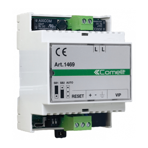
Comelit 1469 Owner's manual

art. 1469
Join us
in taking care
of our planet
SB1
VIP
Art.1469
+ -
L L
RESET
AUTO
SB2
PROGRAMMING MANUAL

Simplebus interface for ViP system
base
Interface for the management of hybrid video entry phone system
configurations with door-entry phones and door entry monitors using
2-wire technology (SimpleBus and SimpleBus 2) and devices using IP
technology for the basic system structure (external units, switchboards,
actuator modules, call logs).
The 2-wire door-entry phones and door entry monitors receive calls
from the ViP external unit and can make calls and forward commands to
ViP devices (self activation, call to main and/or secondary switchboard,
actuator control, view ViP cameras, view RTSP cameras, etc.).
Think before you
print
and use the
interactive links
Help us to save the planet.
Think of the planet before printing this document.
You are reading an interactive document: quickly access the
content you are interested in via links.
| Table of contents |

3
Table of contents
Installing software and connecting to modules 4
Searching for devices to configure 4
Device parameters 6
Information 6
Addressing 6
Directories 6
Lock-release functions 8
Maintenance 9
Restarting the device 9
Resetting the device 10
Updating device firmware 10
Saving the configuration 10
Resetting the configuration 10
| Table of contents |

4
Installing software and connecting to modules
• System requirements: Min. operating system Windows 7-64bit, min. NET Framework: 4.7.2, min. CPU
2GHz Dual Core, min. RAM 4GB; min. free memory 200MB
• Download the ViP Manager software from the website pro.comelitgroup.com and run the installation file,
following the on-screen instructions.
• Connect the modules to the PC as indicated below:
1440
Art. 1449
1441
POE
STANDARD
SWITCH
1595
Searching for devices to configure
fRun the ViP Manager software
1
2
3
fOpen the Options menu [1], click Local connections [2] and select the network interface [3] (if there are
several cards installed, select the one to which the network cable has been connected).
| Table of contents |

5
4
5
6
fArt. 1469 has an Ethernet port configured by default in Auto IP; press Auto IP [4] to assign an IP address
to your PC (the IP Address, Subnet Mask and Default Gateway fields will be completed automatically by
the software). If the IP addressing configuration has already been changed, the local connection should be
configured on the basis of the programming carried out. Only select DHCP enable if the system has been
connected to a server with DHCP protocol or enter the configuration to be assigned to your PC in the IP
address and Subnet mask fields to have the same IP address class as the module.
fConfirm by pressing OK [5]
fStart searching for devices by pressing Scan system [6]
7
fSelect the module [7]
| Table of contents |

6
Device parameters
The parameters used to configure art. 1469 are listed below.
Note: after changing the parameters on a page, you need to press Write page before exiting the section you are
editing, in order to save the changes to the device.
Information
DEVICE INFORMATION
This section shows information relating to the device. The fields cannot be edited.
DEVICE DESCRIPTION
Description: text field used to assign a description to the device.
The description is used to identify devices more easily in the case of complex systems. Once a description has
been set you will be able to see it in the Navigation tree, in the Name column.
Addressing
IP ADDRESS
• IP address mode: select the desired addressing mode.
◊ Auto IP: an IP address will be assigned to the devices automatically (Default).
◊ DHCP: an IP address will automatically be assigned to the devices if the system is connected to a server
with the DHCP function active.
◊ Static: a permanent IP address should be assigned to the devices.
• IP netmask: enter an IP netmask which is compatible with your system (Default: 255.255.0.0).
• Use default gateway: enable the default gateway to provide an Internet connection for the device. An
Internet connection is not required for the device to work, however it is required for receiving automatic
firmware updates (Default: not selected).
• Gateway address: IP address of the default gateway (Default: 0.0.0.0).
• Primary DNS: primary DNS server (Default: 8.8.8.8).
• Secondary DNS: secondary DNS server (Default: 8.8.4.4).
Directories
INTERNAL UNITS
In this directories section, all Simplebus internal units must be programmed with the corresponding call address
and are mapped with the relevant ViP addresses and corresponding lock-release functions.
• Address: enter the Simplebus address for the internal unit to configure on the interface
• Call type
◊ Video call: if the internal unit is audio/video, select this parameter
◊ Audio call: if the internal unit is audio only, select this parameter
• Number of calls: number of ringtone repetitions on receipt of a call from the external unit
• Lock-release function: select one of the three programmable lock-release functions in the lock-release
functions section
| Table of contents |

7
• ViP address: ViP address corresponding to the Simplebus internal unit
• Master / Slave
EXTERNAL UNITS
• External units ViP address: enter the ViP address for all external units that need to be reached by the
Simplebus internal unit
INTERNAL UNITS INPUT FUNCTION (PAN/AL – CFP)
ALARM / PANIC
• Function: action to be carried out if the input is activated.
◊ Disabled: no action.
◊ Priority call 1: while the input is active, a priority call is made to the ViP address set in the switchboard
ViP address parameter.
◊ Priority call 2: while the input is active, a priority call is made to the ViP address set in the switchboard
ViP address parameter.
◊ Priority call 3: while the input is active, a priority call is made to the ViP address set in the switchboard
ViP address parameter.
◊ Priority call 4: while the input is active, a priority call is made to the ViP address set in the switchboard
ViP address parameter.
• Switchboard ViP address: ViP address of the switchboard to which the priority call should be forwarded.
FLOOR DOOR CALL
• Function: action to be carried out if the input is activated.
◊ Disabled: no action.
◊ Priority call 1: while the input is active, a priority call is made to the ViP address set in the switchboard
ViP address parameter.
◊ Priority call 2: while the input is active, a priority call is made to the ViP address set in the switchboard
ViP address parameter.
◊ Priority call 3: while the input is active, a priority call is made to the ViP address set in the switchboard
ViP address parameter.
◊ Priority call 4: while the input is active, a priority call is made to the ViP address set in the switchboard
ViP address parameter.
◊ Switchboard ViP address: ViP address of the switchboard to which the priority call should be forwarded.
ACTUATORS (ACT)
Actuator modules 1443 and SK9071, which need to be controlled by the buttons on the Simplebus internal
units, must be programmed in this section of the directory.
• Actuator code: enter the address of the actuator configured on the buttons of the SimpleBus internal units.
• Actuator module ViP address: enter the ViP address of the actuator module you want to use.
• Expansion index: select where the output to be activated is located, in the actuator module or in one of the
connected expansion devices.
• Output: select the output to be activated on the actuator module or expansion device.
SWITCHBOARDS
• Switchboard ViP address: ViP for the main switchboard and the secondary switchboard that can be called
if the Simplebus internal units are programmed with the relevant call function on one of their buttons.
| Table of contents |

8
VIP CAMERAS
• Actuator code / address: program the Simplebus address programmed on the internal units to examine
the associated cameras.
• Camera ViP address: enter the ViP address for the remote camera module art. 1445H.
• Camera: select the camera connected to the art. 1445H to use.
◊ Camera 1: camera on input 1 of the 1445H.
◊ Camera 2: camera on input 2 of the 1445H.
◊ Camera 3: camera on input 3 of the 1445H.
◊ Camera 4: camera on input 4 of the 1445H.
RTSP CAMERAS
• Actuator code / address: program the Simplebus address programmed on the internal units to examine
the associated cameras.
◊ RTSP Url: RTSP address of the camera.
◊ RTSP User: RTSP server user name.
◊ RTSP Password: RTSP server password.
Lock-release functions
LOCK-RELEASE FUNCTION 1-2-3
LOCK-RELEASE DURING CALL
This section is used to configure the actions to be carried out if a lock-release command is sent, using a
suitably configured button, from the internal unit during a call in progress.
• Action 1: enable action 1
• Relay: select the relay to be activated
◊ SE output: the SE output for the external unit is activated
◊ Relay output: the relay output for the external unit is activated
◊ Virtual output 1: virtual output 1 for the external unit is activated
• Destination:
◊ Caller: the output is activated on the external unit communicating with the internal unit, regardless of the
ViP address.
◊ Port: the output is activated on the external unit identified by the ViP address set in the parameter below.
• ViP address: if the port is selected in the above parameter, you need to enter the ViP address of the
external unit on which you want to control the output.
• Action 2: enable action 2
• Relay: select the relay to be activated
◊ SE output: the SE output for the external unit is activated
◊ Relay output: the relay output for the external unit is activated
◊ Virtual output 1: virtual output 1 for the external unit is activated
• Destination:
◊ Caller: the output is activated on the external unit communicating with the internal unit, regardless of the
ViP address.
◊ Port: the output is activated on the external unit identified by the ViP address set in the parameter below.
• ViP address: if the port is selected in the above parameter, you need to enter the ViP address of the
external unit on which you want to control the output.
| Table of contents |

9
LOCK-RELEASE WITHOUT CALL
This section is used to configure the actions to be carried out if a lock-release command is sent, using a
suitably configured button, from the internal unit while there is no call with an external unit in progress.
• Action 1: enable action 1
• Relay: select the relay to be activated
◊ SE output: the SE output for the external unit is activated
◊ Relay output: the relay output for the external unit is activated
◊ Virtual output 1: virtual output 1 for the external unit is activated
• ViP address: ViP address for the external unit on which the output is to be controlled
• Action 2: enable action 2
• Relay: select the relay to be activated
◊ SE output: the SE output for the external unit is activated
◊ Relay output: the relay output for the external unit is activated
◊ Virtual output 1: virtual output 1 for the external unit is activated
• ViP address: ViP address for the external unit on which the output is to be controlled
Maintenance
Restarting the device
Proceed as follows:
1. Select the module in the Devices list
2. Right-click on the description (a pop-up with 5 sub-menus will appear)
3. Select Restart device or click the button on the menu bar
| Table of contents |

www.comelitgroup.com
Via Don Arrigoni, 5 - 24020 Rovetta (BG) - Italy
CERTIFIED MANAGEMENT SYSTEMS
1ª edizione 10/2023
cod. 2G40002714
Resetting the device
The factory settings of the module can be restored.
Proceed as follows:
1. Select the module in the Devices list
2. Right-click on the description (a pop-up with 5 sub-menus will appear)
3. Select Reset device (an alert/confirm procedure request window appears)
Updating device firmware
Proceed as follows:
1. Select the module in the Devices list
2. Right-click on the description (a pop-up with 5 sub-menus will appear)
3. Select Download firmware or click the button on the menu bar
Saving the configuration
Proceed as follows:
1. Select the module in the Devices list
2. Right-click on the description (a pop-up with 5 sub-menus will appear)
3. Select Save configuration
Resetting the configuration
The module configuration saved previously can be reset.
Proceed as follows:
1. Select the module in the Devices list
2. Right-click on the description (a pop-up with 5 sub-menus will appear)
3. Select Resetting configuration
| Table of contents |
Other manuals for 1469
1
Table of contents
Other Comelit Recording Equipment manuals

Comelit
Comelit 1467 User manual

Comelit
Comelit 3063D User manual

Comelit
Comelit 1622 User manual

Comelit
Comelit 3063U User manual

Comelit
Comelit 1468 Owner's manual

Comelit
Comelit 3064/C User manual

Comelit
Comelit 20005000 User manual

Comelit
Comelit 20003400 User manual

Comelit
Comelit 1469 User manual

Comelit
Comelit 20002611 User manual