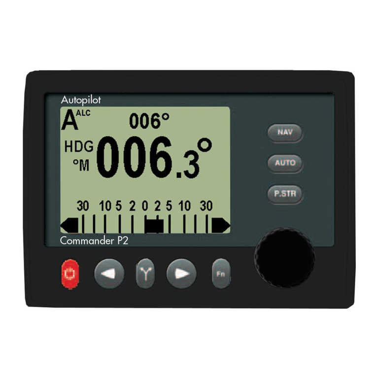
ComNav Commander P2 User manual

Installation & Operation Manual
Commander P2
Advanced Auto
p
ilot S
y
stem
COMPLIES WITH
CE REGULATIONS
PN 29010074


ComNav Commander P2 Installation & Operation Table of Contents, Lists of Figures & Tables
Document PN 29010074 V3.1 - 3 -
Welcome
Congratulations on your purchase of ComNav Marine’s Commander P2 Advanced
Autopilot System! At ComNav, we are proud of our prominence as a leader in the design
and manufacture of marine autopilot systems. Our dedication to performance and
reliability will ensure your satisfaction with the ComNav Commander P2. Developed as a
result of ComNav’s many years of experience in autopilot design, the Commander P2
Advanced Autopilot System provides better performance and more features than any
other autopilot in its class.
ComNav Marine Ltd.
Warranty Notice
Prior to the installation and/or operation of the equipment, ensure that you read,
understand, and accept the conditions of the warranties as detailed in the
Warranty Information document that accompanies this manual.
Operator’s Warning
The Commander P2 Advanced Autopilot System will steer your vessel, however it is only
an aid to navigation. Its performance can be affected by many factors including
equipment failure, environmental conditions, and improper handling or use. The system
does not reduce your responsibility for the control of the vessel when underway. You
must always be in a position to monitor the course, supervise the autopilot, and resume
manual control if the need to do so arises.
Whenever underway, your vessel must be under the control of a qualified and alert
person.
General Notice
This document, ComNav part number 29010075 Version 3 Revision 1, is the approved
Installation and Operation Manual for use with ComNav’s Commander P2 Autopilot
System. Where versions of this manual exist in other languages, the English version
shall be considered authoritative.

ComNav Commander P2 Installation & Operation Table of Contents, Lists of Figures & Tables
Document PN 29010074 V3.1 - 4 -
Document History
Revision Date By Description
1R1 27 April 2005 DC First Release
2R0 04 January 2006 DC Updated for new software release
2R1 29 August 2006 DC & DTO - corrected SPU ⇔NEMA 0183 Connection Diagram to
show correct order of NAV 1 & 2 input pins
- corrected SPU ⇔PC Connection Diagrams to show use of
NAV #1 input pins instead of NAV #2
- added Document History table (this table)
2R2 07 September 2006 DTO - revised Control Head Connection description text, and
associated Wiring Connections Diagram, to include the
new alternative colour-coding of the cable
3R0 27 September 2007 DTO - brand name change
- added info on Vector GPS compasses
- updated compass installation & setup procedures
- updated General Specifications
- revised external Jog Lever connection information
- updated information on SPU connectors & wiring
- Head menu figures are now easier-to-read “screen shots”
- Firmware Upgrade info now in separate kit
- Warranty is now in a separate document
3R1 14 December 2007 DTO - added Compass Safe Distance information, Table 15
- re-organized “modes & menus” information for easier use
- moved all “using the Head” information into one area
- added Wind Vane with NX2 Instrument/Server wiring info,
Figure 40 & Figure 41
- deleted one MPN for fuse F1, Table 7
- updated Error Messages lists, Appendix 2
- updated dimensions, Appendix 6

ComNav Commander P2 Installation & Operation Table of Contents, Lists of Figures & Tables
Document PN 29010074 V3.1 - 5 -
Table of Contents
Welcome......................................................................................................................................................3
Document History ......................................................................................................................................4
Table of Contents.......................................................................................................................................5
List of Figures...........................................................................................................................................11
List of Tables............................................................................................................................................13
About this Manual....................................................................................................................................17
Typefaces, Common Phrases & Terms__________________________________________________________17
Manual Format ____________________________________________________________________________18
How Autopilots Work...............................................................................................................................19
Basic Autopilot System ______________________________________________________________________ 19
Autopilot Operation: Maintaining a Heading ______________________________________________________20
Wind and Current Effects ____________________________________________________________________ 21
Autopilot Operation: Following a Track – NAV Mode _______________________________________________22
Autopilot Operation: Following a Track – AUTO/ALC Mode __________________________________________ 23
Power Steer_______________________________________________________________________________23
System Overview......................................................................................................................................27
Control Head ______________________________________________________________________________28
Signal Processor Unit _______________________________________________________________________ 29
Compasses _______________________________________________________________________________30
Vector G2 and G2B GPS Compasses_________________________________________________________30
Fluxgate Compass________________________________________________________________________ 31
Magnetic Compass Sensor _________________________________________________________________ 31
Magnetic Compasses _____________________________________________________________________ 32
45° Compass Transducer __________________________________________________________________32
Heading Rate Stabilizer____________________________________________________________________ 33
Other Compasses ________________________________________________________________________ 33
Rudder Followers __________________________________________________________________________34
Standard Rotary Rudder Follower & Rudder Linkage_____________________________________________ 34
Heavy Duty Rotary Rudder Follower__________________________________________________________34
Linear Rudder Follower____________________________________________________________________35
Auxiliary Controllers_________________________________________________________________________ 36
CR-203 Remote__________________________________________________________________________ 36
TS-203 Remote__________________________________________________________________________37
Other Controls, Indicators & Sensors ___________________________________________________________38
Jog Levers______________________________________________________________________________38
Rudder Angle Indicator (RAI) – 3”____________________________________________________________38
Twin-Fin Wind Transducer _________________________________________________________________ 39
Rudder Drives and Interfaces _________________________________________________________________ 40
CT7 Thruster Interface ____________________________________________________________________40
Other Drive Boxes________________________________________________________________________41
Pumps & Drives__________________________________________________________________________42
Other Equipment ___________________________________________________________________________ 42

ComNav Commander P2 Installation & Operation Table of Contents, Lists of Figures & Tables
Document PN 29010074 V3.1 - 6 -
Installation ................................................................................................................................................45
Technical Requirements _____________________________________________________________________45
Steering System__________________________________________________________________________45
Power Supply____________________________________________________________________________45
Special Tools ____________________________________________________________________________45
Control Head ______________________________________________________________________________46
Mounting _____________________________________________________________________________46
Electrical Connection____________________________________________________________________46
Compasses _______________________________________________________________________________47
ComNav Fluxgate Compass ________________________________________________________________47
Mounting _____________________________________________________________________________47
Electrical Connection____________________________________________________________________47
Heading Rate Stabilizer____________________________________________________________________48
45° Compass Transducer __________________________________________________________________48
Mounting _____________________________________________________________________________48
Electrical Connection____________________________________________________________________48
Magnetic Compass and Sensor______________________________________________________________48
Mounting _____________________________________________________________________________49
Electrical Connection____________________________________________________________________49
Rudder Follower____________________________________________________________________________50
Rotary Rudder Follower____________________________________________________________________50
Mounting _____________________________________________________________________________50
Electrical Connection____________________________________________________________________51
Heavy Duty Rotary Rudder Follower __________________________________________________________51
Linear Rudder Follower ____________________________________________________________________52
Mounting _____________________________________________________________________________52
Electrical Connection____________________________________________________________________55
Other Equipment ___________________________________________________________________________55
Signal Processor Unit _______________________________________________________________________56
Mounting _____________________________________________________________________________56
Wiring the SPU - General ________________________________________________________________56
Connectors on the SPU__________________________________________________________________57
Wiring the System __________________________________________________________________________58
Power Supply____________________________________________________________________________58
Input & Output Connections_________________________________________________________________60
Control Head __________________________________________________________________________60
Auxiliary Controller(s)____________________________________________________________________60
Jog Levers ____________________________________________________________________________61
Four-Way Valves, Used with Jog Levers_____________________________________________________61
Compasses ___________________________________________________________________________62
Wind Transducer _______________________________________________________________________63
Rudder Follower________________________________________________________________________64
Rudder Angle Indicators _________________________________________________________________65

ComNav Commander P2 Installation & Operation Table of Contents, Lists of Figures & Tables
Document PN 29010074 V3.1 - 7 -
Drive Outputs____________________________________________________________________________ 66
Reversing DC Motor Hydraulic Systems _____________________________________________________ 66
Linear Actuators or Mechanical Rotary Drives ________________________________________________ 66
Shunt-Field Reversing Motors_____________________________________________________________ 67
Standard Four-Way Solenoid-Activated Hydraulic Valves________________________________________ 67
Two-Speed Solenoid Valves ______________________________________________________________68
A.C. Solenoids_________________________________________________________________________ 69
Proportional Solenoid Valves _____________________________________________________________ 69
Azimuth Drives, Surface Piercing Drives and Jet Drives_________________________________________ 70
External Alarm Output_____________________________________________________________________71
NMEA 0183 Input & Output_________________________________________________________________ 73
PC Input & Output ________________________________________________________________________ 74
Other Connections________________________________________________________________________ 75
Miscellaneous I/O ______________________________________________________________________75
Thruster Interface ______________________________________________________________________75
ComNav Network ______________________________________________________________________ 75
Post-Installation Checks _____________________________________________________________________ 76
Electrical Checks_________________________________________________________________________ 76
Hydraulic Checks_________________________________________________________________________ 77
Residual air in the steering system ___________________________________________________________77
Leaking fittings or equipment________________________________________________________________ 77
Getting Started .........................................................................................................................................81
Autopilot Operations ________________________________________________________________________ 81
Power On/Off____________________________________________________________________________81
Using the Control Head – LCD Screen & Buttons________________________________________________82
Operating Modes & Menus ___________________________________________________________________84
Alarm Clear _____________________________________________________________________________ 85
Dockside Setup Menu _____________________________________________________________________ 86
Reset________________________________________________________________________________87
Vessel Type___________________________________________________________________________ 87
An. Comp. Type (Analog Compass Type)____________________________________________________88
Compass Setup________________________________________________________________________89
Drive Setup ___________________________________________________________________________ 89
Exit__________________________________________________________________________________89
Alarm O/P (Alarm Output) ________________________________________________________________89
Thrust Type ___________________________________________________________________________ 91
Thrust MIN____________________________________________________________________________ 91
Thrust MAX ___________________________________________________________________________ 91
Language_____________________________________________________________________________91
Setup Procedures __________________________________________________________________________92
Vessel Type_____________________________________________________________________________92
Drive Setup _____________________________________________________________________________93
Bleeding a Hydraulic Steering System ______________________________________________________ 95
Drive Setup (continued)____________________________________________________________________ 97

ComNav Commander P2 Installation & Operation Table of Contents, Lists of Figures & Tables
Document PN 29010074 V3.1 - 8 -
Compass Setup – Dockside_________________________________________________________________98
Compass Setup – On the Water ____________________________________________________________100
Compass Compensation ________________________________________________________________100
Magnetic Compass Sensor ____________________________________________________________100
Heading Rate Stabilizer_______________________________________________________________101
Fluxgate Compass___________________________________________________________________102
45° Compass Transducer _____________________________________________________________103
Compass Calibration ___________________________________________________________________104
Sea Trials________________________________________________________________________________105
Adjust Rudder Gain & Counter Rudder for Low Speed ___________________________________________105
Adjust Seastate for Low Speed _____________________________________________________________106
Adjust Turn Rate for Low Speed ____________________________________________________________106
Adjust Rudder Gain & Counter Rudder for High Speed___________________________________________106
Adjust Seastate for High Speed_____________________________________________________________106
Adjust Turn Rate for High Speed____________________________________________________________106
Adjusting for Sea Conditions _________________________________________________________________107
Basic Operations....................................................................................................................................111
Standby Mode ____________________________________________________________________________111
Rudder Angle Indicator (RAI)_______________________________________________________________111
Standby Menu __________________________________________________________________________112
Station Lock__________________________________________________________________________112
Default Turn__________________________________________________________________________112
Compass Source ______________________________________________________________________112
Compass Cal (Compass Calibration)_______________________________________________________113
Backlight Level________________________________________________________________________113
Contrast (monochrome only) _____________________________________________________________113
Graphics (monochrome) Display (colour) ___________________________________________________113
Watch Alarm _________________________________________________________________________113
Fishzag Time _________________________________________________________________________113
Battery ______________________________________________________________________________113
Power Steer Mode_________________________________________________________________________114
Power Steer Menu_______________________________________________________________________115
Stdby/P.Str Limits (Power Steer Rudder Limits) ______________________________________________115
Auto/Nav Limits _______________________________________________________________________115
RAI Offset ___________________________________________________________________________115
Auto Mode _______________________________________________________________________________116
Auto Menu _____________________________________________________________________________117
Rudder Gain__________________________________________________________________________117
Counter Rudder _______________________________________________________________________118
Seastate_____________________________________________________________________________118
Turn Rate____________________________________________________________________________118
Parameter Set ________________________________________________________________________119
Speed Trip Pt (Speed Trip Point)__________________________________________________________119
Speed Source ________________________________________________________________________119
ALC (Automatic Leeway Correction) _______________________________________________________119
Thruster Assist________________________________________________________________________119
Thruster Gain_________________________________________________________________________119

ComNav Commander P2 Installation & Operation Table of Contents, Lists of Figures & Tables
Document PN 29010074 V3.1 - 9 -
NAV Mode_______________________________________________________________________________120
Nav Menu _____________________________________________________________________________ 121
Nav Source __________________________________________________________________________ 121
XTE Limit (Cross-Track Error Limit)________________________________________________________121
WayPt. Arrival (Waypoint Arrival) _________________________________________________________ 121
Correction ___________________________________________________________________________122
XTE Sense (Cross-Track Error Sense) _____________________________________________________ 122
Max Correction _______________________________________________________________________122
Commanded Heading Displayed____________________________________________________________ 123
Correction set to CTS – Steering a Direct Bearing____________________________________________123
Correction set to XTE – Cross-Track Error Steering __________________________________________ 124
Correction set to Both – Steering To/Along a Track ___________________________________________ 126
Alternate NAV Display____________________________________________________________________ 128
Dodge __________________________________________________________________________________ 129
Jog Lever Turns___________________________________________________________________________ 132
Advanced Operations............................................................................................................................135
WORK Mode _____________________________________________________________________________ 135
Automatic WORK Mode ________________________________________________________________ 135
Manual WORK Mode___________________________________________________________________ 136
Work Menu ____________________________________________________________________________ 137
Rudder Bias__________________________________________________________________________ 137
Autotrim_____________________________________________________________________________137
Work Trip Pt. (Work Trip Point) ___________________________________________________________137
Rudder Scale (Rudder Scale Factor) ______________________________________________________137
Work Mode State______________________________________________________________________ 137
WIND Mode______________________________________________________________________________ 138
Tacking _______________________________________________________________________________ 139
Gybing________________________________________________________________________________141
Alternate WIND Mode Display______________________________________________________________ 142
Wind Menu ______________________________________________________________________________ 144
Wind Source _________________________________________________________________________144
Wind Shift (Wind Shift Alarm) ____________________________________________________________ 145
Wind Shift Delay ______________________________________________________________________145
Preset Tack Angle_____________________________________________________________________ 145
Close Haul Def _______________________________________________________________________ 145
Close Reach Def ______________________________________________________________________145
Beam Reach Def______________________________________________________________________ 145
Broad Reach Def______________________________________________________________________145
Gybe Hold Point ______________________________________________________________________ 145
Port Tack Alarm_______________________________________________________________________ 145
Stbd. Tack Alarm______________________________________________________________________ 145
Special Turns_____________________________________________________________________________ 146
U-Turn ________________________________________________________________________________ 147
Circle Turn_____________________________________________________________________________ 148
M.O.B. – Man Over-Board_________________________________________________________________ 149
Fishzag _______________________________________________________________________________ 150
Pretack (Preset-Tack) ____________________________________________________________________ 151
Tack__________________________________________________________________________________152
Gybe _________________________________________________________________________________ 153

ComNav Commander P2 Installation & Operation Table of Contents, Lists of Figures & Tables
Document PN 29010074 V3.1 - 10 -
Multiple Control Heads & Auxiliary Controllers ___________________________________________________154
Station Lock/Unlock______________________________________________________________________154
Watch Alarm _____________________________________________________________________________155
Entering the Password____________________________________________________________________156
Changing the Password___________________________________________________________________157
Care & Maintenance...............................................................................................................................161
Cleaning and Appearance ___________________________________________________________________161
Protection of Wires and Cabling ______________________________________________________________161
Periodic Checks___________________________________________________________________________161
Fuse Replacement_________________________________________________________________________162
Appendices.............................................................................................................................................165
Appendix 1_______________________________________________________________________________165
NMEA 0183 Sentences Accepted and Transmitted by the Autopilot_________________________________165
Messages Accepted____________________________________________________________________165
Messages Transmitted__________________________________________________________________167
Appendix 2_______________________________________________________________________________169
Error Messages _________________________________________________________________________169
Appendix 3_______________________________________________________________________________173
Auxiliary Head / Remote Power On__________________________________________________________173
Appendix 4_______________________________________________________________________________175
Diagnostic LEDs ________________________________________________________________________175
Appendix 5_______________________________________________________________________________177
Upgrading Firmware _____________________________________________________________________177
Appendix 6_______________________________________________________________________________179
General Specifications____________________________________________________________________179
Compass Safe Distances__________________________________________________________________180
CE Compliance ___________________________________________________________________________181
Index........................................................................................................................................................185
User Notes & Settings............................................................................................................................191
User Settings _____________________________________________________________________________191

ComNav Commander P2 Installation & Operation Table of Contents, Lists of Figures & Tables
Document PN 29010074 V3.1 - 11 -
List of Figures
Figure 1 – Basic Autopilot System.............................................................................................................................. 19
Figure 2 – Heading Change in AUTO Mode............................................................................................................... 21
Figure 3 – Commander P2 System Block Diagram.................................................................................................... 27
Figure 4 – Control Head.............................................................................................................................................. 28
Figure 5 – The Commander P2 SPU with Wiring & Diagnostic Covers Removed..................................................... 29
Figure 6 – Vector G2 GPS Compass.......................................................................................................................... 30
Figure 7 – Fluxgate Compass..................................................................................................................................... 31
Figure 8 – Magnetic Compass Sensor........................................................................................................................ 31
Figure 9 – Externally Gimballed Magnetic Compass with Binnacle............................................................................ 32
Figure 10 – 45° Compass Transducer........................................................................................................................ 32
Figure 11 – Heading Rate Stabilizer........................................................................................................................... 33
Figure 12 – Rotary Rudder Follower........................................................................................................................... 34
Figure 13 – Heavy Duty Rotary Rudder Follower....................................................................................................... 34
Figure 14 – Linear Rudder Follower ........................................................................................................................... 35
Figure 15 – CR-203 Handheld Remote ...................................................................................................................... 36
Figure 16 – TS-203 Fixed Remote.............................................................................................................................. 37
Figure 17 – Jog Lever................................................................................................................................................. 38
Figure 18 – External Rudder Angle Indicator - 3" Model ............................................................................................ 38
Figure 19 – Twin-Fin Wind Transducer....................................................................................................................... 39
Figure 20 – CT7 Interface........................................................................................................................................... 40
Figure 21 – Drive Boxes to meet all needs................................................................................................................. 41
Figure 22 – Hydraulic Pump & Solenoid Value........................................................................................................... 42
Figure 23 – Cable Drives ............................................................................................................................................ 42
Figure 24 – Rudder Follower Linkage Geometry........................................................................................................ 51
Figure 25 – Typical Arrangement of Linear Rudder Follower on an Outboard’s Steering Cylinder............................ 52
Figure 26 – Band Clamp and Plastic Brackets ........................................................................................................... 53
Figure 27 – Installed Arrangement of Brackets........................................................................................................... 53
Figure 28 – Fasteners, Stainless Bracket Arrangement............................................................................................. 54
Figure 29 – Removal of SPU Wiring Cover ................................................................................................................ 57
Figure 30 – SPU Connector Wiring Label................................................................................................................... 57
Figure 31 – Typical Battery Connection to SPU ......................................................................................................... 58
Figure 32 – Typical Battery Connection to Drive Boxes ............................................................................................. 59
Figure 33 – Reducing Supply Voltage Losses............................................................................................................ 59
Figure 34 – Wiring Connections for Control Head, Handheld Remotes, and Fixed Remotes.................................... 60
Figure 35 – Wiring Connections for Jog Levers.......................................................................................................... 61
Figure 36 – Wiring Connections for Four-Way Valves with Jog Levers...................................................................... 61
Figure 37 – Wiring Connections for Analog Compasses............................................................................................ 62
Figure 38 – Wiring Connections for 45° Compass Transducer .................................................................................. 62
Figure 39 – Wiring Connections for Twin-Fin Wind Transducer................................................................................. 63
Figure 40 – Wind Transducer with NX2 Wind Data Instrument.................................................................................. 63
Figure 41 – Wind Transducer with Classic Nexus or NX2 Network Server................................................................ 64
Figure 42 – Wiring Connections for Rudder Followers............................................................................................... 64
Figure 43 – Wiring Connections for Rudder Angle Indicators..................................................................................... 65
Figure 44 – Wiring Connections for Reversing DC Motors......................................................................................... 66
Figure 45 – Wiring Connections for Linear Actuators or Mechanical Rotary Drives................................................... 66
Figure 46 – Wiring Connections for Shunt Field Reversing Motors............................................................................ 67
Figure 47 – Wiring Connections for Standard Four-Way Solenoid Valves................................................................. 67
Figure 48 – Wiring Connections for Constant Running Electric Pump. ...................................................................... 68
Figure 49 – Wiring Connections for Two-Speed Solenoid Valves.............................................................................. 68
Figure 50 – Wiring Connections for A.C. Solenoids.................................................................................................... 69
Figure 51 – Wiring Connections for Proportional Solenoid Valves............................................................................. 69
Figure 52 – Wiring Connections for Isolation Amplifiers............................................................................................. 70
Figure 53 – External Alarm, using SW'D B- Output.................................................................................................... 71
Figure 54 – External Alarm, using SW'D B+ Output................................................................................................... 71
Figure 55 – External Alarm, SW'D B- Output – with Power Fail Option...................................................................... 72
Figure 56 – External Alarm, SW'D B+ Output – with Power Fail Option..................................................................... 72
Figure 57 – Typical NMEA 0183 Connections............................................................................................................ 73
Figure 58 – Connection to a PC with a DE-9 Connector ............................................................................................ 74
Figure 59 – Connection to a PC with a DB-25 Connector .......................................................................................... 74

ComNav Commander P2 Installation & Operation Table of Contents, Lists of Figures & Tables
Document PN 29010074 V3.1 - 12 -
Figure 60 – Power Off Sequence................................................................................................................................81
Figure 61 – Using the Control Head............................................................................................................................82
Figure 62 – A Typical Menu.........................................................................................................................................84
Figure 63 – Entering Dockside Setup..........................................................................................................................86
Figure 64 – Dockside Setup menu, page 1.................................................................................................................87
Figure 65 – Dockside Setup menu, page 2.................................................................................................................89
Figure 66 – External Alarm Configuration ...................................................................................................................90
Figure 67 – External Alarm Type Configuration ..........................................................................................................90
Figure 68 – Set Vessel Type.......................................................................................................................................92
Figure 69 – Move Rudder to Starboard.......................................................................................................................93
Figure 70 – Move Rudder to Port................................................................................................................................94
Figure 71 – Center the Rudder....................................................................................................................................94
Figure 72 – Adding Fluid Capacity ..............................................................................................................................95
Figure 73 – Bleeding Cylinder, Rod moving left..........................................................................................................96
Figure 74 – Bleeding Cylinder, Rod moving right........................................................................................................96
Figure 75 – Drive Test OK...........................................................................................................................................97
Figure 76 – Set Compass Type...................................................................................................................................98
Figure 77 – Compass Verification (Mag Sensor shown).............................................................................................99
Figure 78 – Compass Verification Failed.....................................................................................................................99
Figure 79 – Fluxgate Compass Verification & Compensation...................................................................................102
Figure 80 – Compensation Failed ... Move Compass...............................................................................................103
Figure 81 – Typical Standby Mode Screen ...............................................................................................................111
Figure 82 – Standby Menu (pages 1 & 2) .................................................................................................................112
Figure 83 – Typical Power Steer Mode Screen.........................................................................................................114
Figure 84 – Power Steer Menu..................................................................................................................................115
Figure 85 – Typical Auto Mode Screen.....................................................................................................................116
Figure 86 – Auto Menu, pages 1 & 2.........................................................................................................................117
Figure 87 – Guidelines for setting Rudder Gain........................................................................................................117
Figure 88 – Guidelines for setting Counter Rudder...................................................................................................118
Figure 89 – HI and LO Speed Icons (Left of Rudder Angle Indicator)......................................................................119
Figure 90 – Typical NAV Mode Screen (Normal Display).........................................................................................120
Figure 91 – Nav Menu, pages 1 & 2..........................................................................................................................121
Figure 92 – Steering with Correction set to CTS.......................................................................................................123
Figure 93 – Steering with Correction set to XTE.......................................................................................................124
Figure 94 – Response of Vessel to a Large Cross-Track Error ................................................................................125
Figure 95 – Steering with Correction set to Both.......................................................................................................126
Figure 96 – Typical NAV Mode Screen (Alternate Display) ......................................................................................128
Figure 97 – A Dodge in Progress (in AUTO Mode)...................................................................................................129
Figure 98 – Vessel Track During a Dodge Manoeuvre in AUTO Mode ....................................................................130
Figure 99 – Holding at a Heading Part-way Through a Dodge Turn.........................................................................131
Figure 100 – Typical Jog Lever Activated Screen.....................................................................................................132
Figure 101 – Typical WORK Mode Screen (Engaged) .............................................................................................135
Figure 102 – WORK Mode Menu..............................................................................................................................137
Figure 103 – Typical WIND Mode Screen (Normal Display).....................................................................................138
Figure 104 – WIND Mode Tack Query......................................................................................................................139
Figure 105 – Tack Response for Various Points of Sail............................................................................................140
Figure 106 – Gybe Response for Various Points of Sail...........................................................................................141
Figure 107 – Typical ALTERNATE WIND Mode Screen...........................................................................................142
Figure 108 – Commanded Wind Angle Changed to 90°...........................................................................................143
Figure 109 – Arrow Outline Shows Commanded Wind Angle...................................................................................143
Figure 110 – Wind Menu, pages 1 & 2......................................................................................................................144
Figure 111 – Typical Special Turn Query..................................................................................................................146
Figure 112 – U-Turn Query .......................................................................................................................................147
Figure 113 – U-Turn Vessel Path..............................................................................................................................147
Figure 114 – Circle Turn Query.................................................................................................................................148
Figure 115 – Circle Turn Vessel Path........................................................................................................................148
Figure 116 – M.O.B. Turn Query...............................................................................................................................149
Figure 117 – M.O.B. Turn Vessel Path......................................................................................................................149
Figure 118 – Fishzag Turn Query..............................................................................................................................150
Figure 119 – Fishzag Turn ........................................................................................................................................150

ComNav Commander P2 Installation & Operation Table of Contents, Lists of Figures & Tables
Document PN 29010074 V3.1 - 13 -
Figure 120 – PreTack Turn Query ............................................................................................................................ 151
Figure 121 – Tack Query in Regular (left) and Alternate (right) AUTO-WIND Modes.............................................. 152
Figure 122 – Gybe Query in Regular (left) and Alternate (right) AUTO-WIND Modes............................................. 153
Figure 123 – Station Lock Icons on Main (left) and Aux. Control Head, when In-command (right).......................... 154
Figure 124 – Password Query Pop-Up Window....................................................................................................... 156
Figure 125 – New Password Pop-Up Window.......................................................................................................... 157
Figure 126 – JP12 & JP13 in Factory Default Position (left) and After Moving Shunts (right).................................. 173
List of Tables
Table 1 – Minimum Recommended Wire Gauges...................................................................................................... 56
Table 2 – NMEA Signal Translation Guide................................................................................................................. 74
Table 3 – Vessel Types............................................................................................................................................... 87
Table 4 – Analog Compass Types.............................................................................................................................. 88
Table 5 – NAV Mode Correction............................................................................................................................... 122
Table 6 – Wind Source Selection.............................................................................................................................. 144
Table 7 – Fuse Replacement Guide ......................................................................................................................... 162
Table 8 – NMEA 0183 Sentences Accepted by the Commander P2 ....................................................................... 165
Table 9 - NMEA Sentence Priority............................................................................................................................ 166
Table 10 – Warning Messages ................................................................................................................................. 169
Table 11 – Error Messages....................................................................................................................................... 170
Table 12 – Critical Error Messages........................................................................................................................... 171
Table 13 – Diagnostic LEDs...................................................................................................................................... 175
Table 14 – General Specifications............................................................................................................................ 179
Table 15 – Compass Safe Distances........................................................................................................................ 180
Table 16 – User Settings........................................................................................................................................... 193

ComNav Commander P2 Installation & Operation
Document PN 29010074 V3.1 - 14 -

ComNav Commander P2 Installation & Operation
Document PN 29010074 V3.1 - 15 -
Introduction

ComNav Commander P2 Installation & Operation
Document PN 29010074 V3.1 - 16 -

ComNav Commander P2 Installation & Operation About This Manual
Document PN 29010074 V3.1 - 17 -
About this Manual
This manual provides essential information for the safe and reliable operation of the
ComNav Commander P2 Advanced Autopilot System. You are urged to read this
manual in its entirety before you use your autopilot for the first time, and to keep it handy
until you become thoroughly familiar with the operation of your autopilot.
Typefaces, Common Phrases & Terms
Throughout this manual, you will see a number of different typefaces used, and several
commonly-used words & phrases with very specific meanings, to describe concepts &
actions that are fundamental to the operation of the autopilot. Please take a moment to
become familiar with the following items:
Modes of Operation
Specific “modes of operation” are placed in bold uppercase lettering.
Example: POWER STEER mode.
Button
Commander P2 Control Head buttons and controls are placed in uppercase lettering.
Example: the TURN button.
System Component
Specific System Components are capitalized.
Example: The Control Head, or a Fluxgate Compass
LCD Display
Text that appears in the LCD display is in quotation marks.
Example: “Waypoint Arrival”
press or momentary press
Press and release the indicated button.
double-press
Press and release the indicated button twice in rapid succession.
Although this sounds a little complicated, it is actually very easy to do. Many users
familiar with desktop computers perform a similar function when they “double-click” their
mouse pointer.
press and hold
Press and hold the indicated button for a minimum of one-half of a second.
This time delay is purposely programmed into the system’s response to some buttons, to
prevent casual or accidental activation of the button function. For example, pressing the
Fn button can, depending on system configuration, drastically alter the steering
performance of the Autopilot.
maintain
Hold the indicated button for as long as required to achieve a given result.
Example: To dodge an obstacle in the water, press either the PORT ARROW or
STARBOARD ARROW button, and maintain it in that position until the vessel has dodged
clear of the obstacle in its path.

ComNav Commander P2 Installation & Operation About This Manual
Document PN 29010074 V3.1 - 18 -
Manual Format
This manual has been formatted to be printed on both sides of the pages of the manual,
and on standard Letter-sized paper (8.5” x 11”). If you have obtained this manual as a
soft-copy, please note that it is in Adobe® Portable Document Format (“pdf”), and so may
be viewed & printed with Adobe Reader®, or compatible pdf-format viewers.
When printing this manual with Reader, you should select “duplex printing” (or the
equivalent term used by your printer’s software driver), in order to print it double-sided on
the paper. If your printer does not have built-in duplexing capability, you can still print this
manual double-sided by following the instructions that came with your printer for doing
“hand duplexing”.

ComNav Commander P2 Installation & Operation How Autopilots Work
Document PN 29010074 V3.1 - 19 -
How Autopilots Work
The purpose of this section is to briefly describe what an autopilot does and some of the
things you should expect when using an autopilot with your boat. The information in this
section can be applied in general to any ComNav autopilot, and is not specific to the
Commander P2 Autopilot.
Basic Autopilot System
Figure 1 is a block diagram of the major components of an autopilot system.
COMPASS
READS THE VESSEL'S
ACTUAL HEADINGAND
SENDS IT TO THE SPU
PROCESSOR (SPU)
CALCULATES THE RUDDER
POSITIONNEEDED TO STEER
THE VESSEL ON THE DESIRED
HEADING, AND CONTROLS THE
STEERINGSYSTEM
ACCORDINGLY
STEERING SYSTEM(ACTUATOR)
[HYDRAULICRAMORELECTRICMOTOR
WHICH IS MECHANICALLY CONNECTED
TO THE RUDDER]
MOVES THE RUDDER IN RESPONSE TO
CONTROL SIGNALS FROM THE SPU
RUDDER FOLLOWER UNIT (RFU)
[MECHANICALLY CONNECTED TO RUDDER]
MEASURES RUDDER POSITION AND SENDS
ITTOTHESPU
NAVIGATION DEVICES
[OPTIONAL]
SUPPLY NAVIGATION
INFOMRATION TOTHE SPU
INNMEA0183FORMAT
CONTROL HEAD
DISPLAYS STATUS AND HEADING
INFORMATIONFROMTHESPU, AND
ALLOWS THE OPERATOR TO INPUT
STEERING COMMANDS & OPERATING
PARAMETERS
Figure 1 – Basic Autopilot System
The Compass indicates the direction in which the boat is pointed – often referred to as the
Actual Heading. Depending on the type of boat & installed equipment, the Compass may be
a magnetic compass, an electronic fluxgate compass, a gyroscopic compass, or a GPS
Compass. A reliable compass is absolutely vital to the autopilot – because, without a
compass, the autopilot has no way of knowing which way the boat is headed.
The actual heading is fed electronically from the Compass to the Processor (SPU) , which is
the heart of the autopilot. The SPU contains the microprocessor(s) & other electronic
hardware, and the sophisticated control software necessary to steer the boat on any Desired
Heading.

ComNav Commander P2 Installation & Operation How Autopilots Work
Document PN 29010074 V3.1 - 20 -
The Control Head, normally located in the wheelhouse, is the interface between the user
(that’s you …) and the autopilot. The Control Head displays information about what the
autopilot is doing. It has various controls (buttons &/or knobs) that allow the user to give
commands to the Autopilot.
The final part of the picture is the Steering System. In order for the autopilot to steer the
boat, there must be some a steering system (i.e., actuator) capable of moving the rudder
independently of the ship’s wheel. This might be a hydraulic ram that is connected to the
rudder post or tiller quadrant, or an electric motor connected to the steering cables.
Electronic signals from the SPU signal the steering system to move the rudder. Your
autopilot also will have a Rudder Follower Unit (RFU), a device that tells the SPU what
position the rudder is in at any given time.
Autopilot Operation: Maintaining a Heading
Say, for example, the autopilot was steering your boat Southwest, and you wished to change
direction to Southeast.
That’s easy – if you are using your ComNav Autopilot in AUTO mode.
To initiate the turn, you would turn the knob on the Control Head to set the Desired Heading
(as shown on the Control Head’s display screen) to 135° – i.e., Southeast.
The SPU then would compare this to the boat’s current Actual Heading of 225° (Southwest),
as indicated by the Compass, and determine that the Desired Heading is 90° to Port of the
Actual Heading. This in turn would cause the SPU to send a signal to the steering system to
move the Rudder to Port – so that the boat turns to Port. The SPU verifies that the Rudder
has moved by reading its position from the Rudder Follower Unit.
As the boat turns, the difference between the Desired Heading and the Actual Heading gets
smaller, and as it does, the SPU then starts to ‘back off” the rudder – i.e., move it back to
centre – so that the boat does not overshoot the Desired Heading.
Eventually, the Actual Heading will match the Desired Heading. The SPU will keep steering
the boat on a heading of 135°, until new instructions are received from the Control Head.
Figure 2 shows a vessel making that Southwest-to-Southeast turn in AUTO mode.
ComNav Autopilots provide an important safety feature in AUTO mode: when you first select
the mode, the autopilot will use the current Actual Heading as the Desired Heading. This
feature prevents the autopilot from executing an unexpected turn when you first select AUTO
mode.
Other manuals for Commander P2
2
Table of contents
Other ComNav Marine Equipment manuals
Popular Marine Equipment manuals by other brands

Raymarine
Raymarine E-Series installation instructions

Ziton
Ziton ZP755HA-2 Installation sheet

B & G
B & G H3000 Pilot owner's manual

Raymarine
Raymarine SmartPilot ST7001 operating guide

Yacht Devices
Yacht Devices YDNU-02RM user manual

Aeware
Aeware Fully and truly waterproof dvd/cd/mp3 player & am-fm... user manual