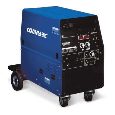
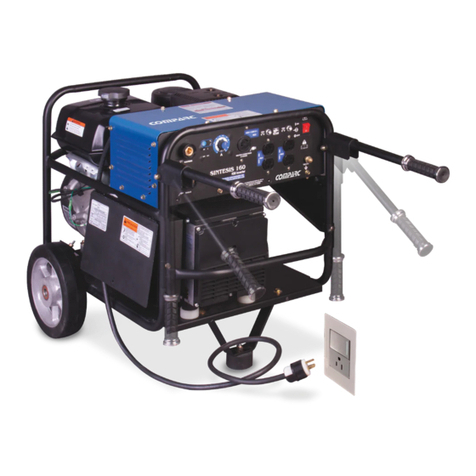
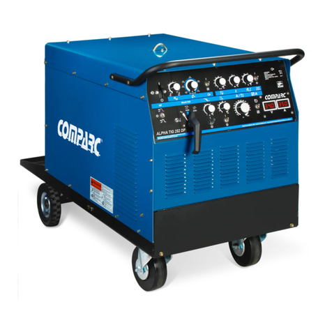
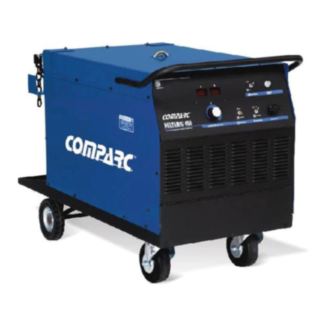
Comparc BRONCO 255K XD User manual

OWNER´S MANUAL
BRONCO255KXD
ENGINE DRIVEN WELDING GENERATOR
PROCESS
STICK (SMAW)
DESCRIPTION
(CC / CV)
TIG (GTAW)
MIG(GMAW)
WELDINGGENERATORTYPE:AC/DC.
CONSTANTCURRENT/CONSTANTVOLTAGE
CC
CV
PM1323 REV. 0
E: 21-01-2021
304-855
T M
OWNER´S MANUAL
GIVETHISMANUALTOTHEOPERATOR
VISIT OUR WEBSITE AT: www.comparcwelders.ca

TABLE OF CONTENS
ARCELECTRICWELDINGSAFETYPRECAUTIONS ..............................................................................................................................i
SECTION1--SAFETYSIGNALWORDS ...............................................................................................................................................1
1 - 2 Symbol usage and definition ................................................................................................................................................1
SECTION 2 SPECIFICATIONS ...........................................................................................................................................................2
2 - 1 Specifications............................................................................................................................................................................2
2 - 2 Fuel Consumption Curves .....................................................................................................................................................2
2 - 3 AC Auxiliary Power ...................................................................................................................................................................2
2 - 4 Volts - Amperes Curves..........................................................................................................................................................3
2 - 5 Duty Cylce...................................................................................................................................................................................3
SECTION 3 INSTALLATION ...............................................................................................................................................................4
3 - 1 Selection A Location & Moving Welding Source...............................................................................................................4
3 - 2 Overall Dimensions .................................................................................................................................................................4
3 - 3 Exhaust Pipe..............................................................................................................................................................................4
3 - 4 Battery connections .................................................................................................................................................................5
3 - 5 Engine Prestarts Checks .......................................................................................................................................................5
3 - 6 Connecting To Ground The Welding Generator...............................................................................................................6
3 - 7 Connectin Output Terminals .................................................................................................................................................6
3 - 8 Selecting & Preparing Weld Output Cables ......................................................................................................................7
SECTION 4 OPERATION...................................................................................................................................................................7
4 - 1 Controls ......................................................................................................................................................................................7
4 - 2 Polarity Selector AC/DC ..........................................................................................................................................................8
4 - 3 Coarse range selector ............................................................................................................................................................8
4 - 4 Hourmeter ..................................................................................................................................................................................8
4 - 5 Amperage/voltage fine control ..............................................................................................................................................9
4 - 6 Engine Control ..........................................................................................................................................................................9
4 - 7 Burnbank (Optional) ...............................................................................................................................................................9
4 - 8 Mig welding outputs and settings controls .................................................................................................................... 10
4 - 9 Optional controlsand indicators.....................................................................................................................11
SECTION 5 AUXILIARY POWER ................................................................................................................................................... 12
5 - 1 Receptacles........................................................................................................................................................................... 12
5 - 2 Wiring instructions for AC plugs ...................................................................................................................................... 13
5 - 3 Electrical appliances used whit BRONCO 255 XD ..................................................................................................... 13
SECTION 6 MAINTENANCE & TROUBLESHOOTINGS ............................................................................................................. 14
6 - 1 Routine Manitenance .......................................................................................................................................................... 14
6 - 2 Engine Maintenance............................................................................................................................................................ 15
6 - 3 Air Filter Maintenance.......................................................................................................................................................... 16
6 - 4 Oil Change, Oil Filter And Fuel Filter .............................................................................................................................. 16
6 - 5 Connecting or replacing the battery ............................................................................................................................... 17
6 - 6 Adjustment engine speed .................................................................................................................................................. 18
6 - 7 Excitation windings protection .......................................................................................................................................... 19
6 - 8 Engine electric system Protection .................................................................................................................................. 19
6 - 9 Troubleshootings .................................................................................................................................................................. 20
Table 6-1 Welding Trouble ........................................................................................................................................................... 20
Table 6-2 Auxiliary Power Trouble.............................................................................................................................................. 20
Table 6-3 Engine Trouble .............................................................................................................................................................21
SECTION 7 ELECTRICAL DIAGRAM............................................................................................................................................ 22
SECTION 8 AUXILIAR POWER GUIDE ....................................................................................................................................... 23
8 - 1 How Much Power Does Equipment Required .............................................................................................................. 23
8 - 2 How Much Power Does Supply The Generator ............................................................................................................ 23
SECTION 9 PARTS LIST ................................................................................................................................................................ 26

ARC WELDING SAFETY PRECAUTIONS
WARNING
- DANGER! - Indicates a hazardous situation which, if not avoided, will result in death or serious injury. The possible hazards
are shown in the adjoining symbols or explained in the text
- Indicates a hazardous situation which, if not avoided, could result in death or serious injury. The possible hazards are shown
in the adjoining symbols or explained in the text.
- The symbols shown below are used throughout this manual to call attention to and identify possible hazards. When you
see the symbol, watch out, and follow the related instructions to avoid the hazard. The safety information given below is
only a summary of the more complete safety information found in the Safety Standards.
- Only qualified persons should install, operate, maintain, and
repair this unit.
- During operation, keep everybody, especially children, away.
ARC WELDING can be hazardous.
ELECTRIC SHOCK can kill.
Touching live electrical parts can cause fatal shocks
or severe burns. The electrode and work circuit is
electrically live whenever the output is on. The input
power circuit and machine internal circuits are also
live when power is on. In semiautomatic or automatic
wire welding, the wire, wire reel, drive roll housing,
and all metal parts touching the welding wire are electrically live.
Incorrectly installed or improperly grounded equiment is a hazard.
1.- Do not touch live electrical parts.
2.- Wear dry, hole-free insulating gloves and body protection.
3.- Insulate yourself from work and ground using dry insulating
mats or covers.
4.- Disconnect input power or stop engine before installing or
servicing this equipment.
5.- Properly install and ground this equipment according to this
Owner's Manual and national, state, and local codes.
6.- Turn off all equipment when not in use.
7.- Do not use worn, damaged, undersized, or poorly spliced cables.
8.- Do not wrap cables around your body.
9.- Ground the workpiece to a good electrical (earth) ground.
10.- Do not touch electrode while in contact with the work (ground)
circuit.
11.- Use only well-maintained equipment. Repair or replace damaged
parts at once.
12.- Wear a safety harness to prevent falling if working above floor
level.
13.- Keep all panels and cover securely in place.
ARC RAYS can burn eyes and skin;
NOISE can damage hearing.
Arc rays from the welding process produce intense
heat and strong ultraviolet rays that can burn eyes and
skin. Noise from some processes can damage hearing.
1.- Wear a welding helmet fitted with a proper shade
of filter (see ANSIZ49.1 listed in Safety Standards) to protect
FUMES AND GASES can be hazardous
to your health.
Welding produces fumes and gases. Breathing these
fumes and gases can be hazardous to your health.
1.- Keep your head out of the fumes. Do not breath the fumes.
2.- If inside, ventilate the area and / or use exhaust at the arc to remove
welding fumes and gases.
3.- If ventilation is poor, use an approved air-supplied respirator.
4.- Read the Material Safety Data Sheets (MSDSs) and the
manufacturer´s instruction for metal, consumables, coatings, and
cleaners.
5.- Work in a confined space only if it is well ventilated, or while wearing
an air-supplied respirator. Shielding gases used for welding can
displace air causing injury or death. Be sure the breathing air is safe.
6.- Do not weld in locations near degreasing, cleaning, or spraying
operations. The heat and rays of the arc can react with vapors to
form highly toxic and irritating gases.
7.- Do not weld on coated metals, such as galvanized, lead, or cadmium
plated steel, unless the coating is removed from the weld area, the
area is well ventilated, and if necessary, while wearing an air-
supplied respirator. The coatings and any metals containing these
elements can give off toxic fumes if welded.
FLYING SPARK AND HOT METAL can
cause injury
Chipping and grinding cause flying metal . As welds
cool, they can throw off slag.
1.- Wear approved face shield or safety goggles. Side shields
recommended.
2.- Wear proper body protection to protect skin.
your face and eyes when welding or watching.
2.- Wear approvedsafety glasses. Side shields recommended.
3.- Use protective screens or barriers to protect others from flash and
glade; warn others not to watch the arc.
4.- Wear protective clothing made from durable, flame- resistant mate
rial (wool and leather) and foot protection.
5.- Use approved ear plugs or ear muffs if noise level is high.
i

CYLINDERS can explode if damaged.
Shieldinggas cylinders contain gas under high pressure.
If damaged, a cylinder can explode. Since gas cylinders
are normally part of the welding process, be sure to
treat them carefully.
1.- Protect compressed gas cylinders from excessive heat, mechanical
shocks, and arcs.
2.- Install and secure cylinders in an upright position by chaining them
to a stationary support or equipment cylinder rack to prevent falling
or tipping.
3.- Keep cylinders away from any welding or other electrical circuits.
4.- Never allow a welding electrode to touch any cylinder.
5.- Use only correct shielding gas cylinders, regulators, hoses, and
fittings designed for the specific application; maintain them and
associated parts in good condition.
6.- Turn face away from valve outlet when opening cylinder valve.
7.- Keep protective cap in place over valve except when cylinder is in
use or connected for use.
8.- Readand follow instructions on compressed gas cylinders, associated
equipment, and CGA publication P-1 listed in Safety Standards.
ENGINES can be hazardous.
WARNING
ENGINE EXHAUST GASES can kill.
Engines produce harmful exhaust gases.
1.- Use equipment outside in open, well-ventilated
areas.
2.- If used in a closed area, vent engine exhaust outside and away from
any building air intakes.
ENGINE FUEL can cause fire or
explosion.
Engine fuel is highly flammable.
1.- Stop engine before checking or adding fuel.
2.- Do not add fuel while smoking or if unit is near any sparks or open
flames.
3.- Allow engine to cool before fueling. If possible, check and add fuel
to cold engine before beginning job.
4.- Do not overfill tank - allow room for fuel to expand.
5.- Do not spill fuel. If fuel is spilled, clean up before starting engine.
MOVING PARTS can cause injury.
Moving parts, such as fans, rotors, and belts can cut
fingers and hands and catch loose clothing.
1.- Keep all doors, panels, covers, and guards closed
and securely in place.
2.- Stop engine before installing or connecting unit.
3.- Have only qualified people remove guards or covers for maintenance
and troubleshooting as necessary.
4.- To prevent accidental stating during servicing, disconnect negative
(-) battery cable from battery.
5.- Keep hands, hair, loose clothing, and tools away from moving parts.
6.- Reinstall panels or guards and close doors when servicing is finished
and before starting engine.
SPARKS can cause BATTERY GASES
TO EXPLODE; BATTERY ACID can
burn eyes and skin.
Batteries contain acid and generate explosive gases.
1.- Always wear a face shield when working on a
battery.
2.- Stop engine before disconnecting or connecting battery cables.
3.- Do not allow tools to cause sparks when working on a battery.
4.- Do not use welder to charge batteries or jump start vehicles.
5.- Observe correct polarity (+ and -) on batteries.
WELDING can cause fire or explosion.
Sparks and spatter fly off from the welding arc. The
flying sparks and hot metal, weld spatter, hot workpiece,
and hot equipment can cause fires and burns. Acciden-
tal contact of electrode or welding wire to metal objects
can cause sparks, overheating, or fire.
1.- Protect yourself and others from flying sparks and hot metal.
2.- Do not weld where flying sparks can strike flammable material.
3.- Remove all flammables within 35ft (10.7 m) of the welding arc. If
this is not possible, tightly cover them with approved covers.
4.- Be alert that welding sparks and hot materials from welding can
easily go through small cracks and openings to adjacent areas.
5.- Watch for fire, and keep a fire extinguisher nearby.
6.- Be aware that welding on a ceiling, floor, bulkhead, or partition can
cause fire on the hidden side.
7.- Do not weld on closed containers surch as tanks or drums.
8.- Connect work cable to the work as close to the welding areas as
practical to prevent welding current from traveling long, possibly
unknown paths and causing electric shock and fire hazards.
9.- Do not use welder to thaw frozen pipes.
10.- Remove stick electrode from holder or cut off welding wire at
contact tip when not in use.
11.- Wear oil-free protective garments such as leather gloves, heavy
shirt, cuffless trousers, high shoes, and a cap.
ii

STEAM AND PRESSURIZED HOT
COOLANT can burn face, eyes, and
skin.
The coolant in the radiator can be very hot and under
pressure.
1.- Do not remove radiator cap when engine is hot. Allow engine to cool.
2.- Wear gloves and put a rag over cap area when removing cap.
3.- Allow pressure to escape before completely removing cap.
- Additional Symbols For Installation, Operation, And Maintenance
NOISE can damage hearing.
Noise from some processes or equipment can damage hearing.
- Wear approved ear protection if noise level is high.
FALLING EQUIPMENT can injure
-Use lifting eye to lift unit and properly installed
accessories only, NOT gas cylinders. Do not
exceed maximum lift eye weight rating (see
Specifications).
-Use equipment of adequate capacity to lift and support unit.
-If using lift forks to move unit, be sure forks arelong enough to extend
beyond opposite side of unit.
-Keep equipment (cables and cords) away from moving vehicles
when working from an aerial location.
OVERUSE can cause OVERHEATING
-Allow cooling period; follow rated duty cycle.
-Reduce current or reduce duty cycle before starting to
weldagain.
-Do not block or filter airflow to unit.
STATIC (ESD) can damage PC boards.
-Put on grounded wrist strap BEFORE handling boards or parts.
-Use proper static-proof bags and boxes to store, move, or ship PC boards.
ARC WELDING can cause interference.
-Electromagnetic energy can interfere with sensitive
electronic equipment such as microprocessors, computers,
and computer-driven equipment such as robots.
-Be sure all equipment in the welding area is
electromagnetically compatible.
- To reducepossible interference, keep weldcables as short as possible, close
together, and down low, such as on the floor.
-Locate welding operation 100 meters from anysensitive electronic equipment.
-Besurethisweldingmachineisinstalledandgroundedaccordingtothismanual.
-If interference still occurs, the user must take extra measures such as moving
thewelding machine,usingshieldedcables, usingline filters,or shieldingthe work
area.
-Read and follow all labels and the Owner’s Manual carefully before installing, operating, or servicing unit.
Read the safety information at the beginning of the manual and in each section.
- Definitions
iii

PM1323
1-2 Symbol usage and definition.
Start
Engine
Do not switch
while welding
Welding Arc
(Electrode) Stick
(SMAW)
Engine
Choke Read
operator´s
Manual
Stop
Engine
Engine
oil
Fast
(Run, weld / Power)
Fuel
Hours
Seconds
Time
Ground
Positive
Negative
Alternating
Current
MIG (GMAW)
Wire
Battery
Volts
Amperes
Circuit Breaker
Slow (Idle)
Fast/slow
Output
Work
Connection
Check Valve
Clearance
TIG (GTAW)
1-1 Safety signal words.
SECTION 1 - SAFETY SIGNALS AND SYMBOLS
WARNING
CAUTION
IMPORTANT: Statements identify special instructionsnecessaryforthemost efficientoperationofthisequipment.
WARNING statements identify procedures or practices which must be followed to
avoid seriuos personal injury or loss of life.
CAUTION statements identify procedures or practices which must be followed to
avoid minor personal injury or damage to this equipment.
Thefollowingsafetyalertsymbolandsignalwordsareusedthroughoutthismanualtocallattentiontoandidentifydifferent
levelsof hazardandspecialinstructions.
1

PM1323
0 25 50 75 100 125 150 175 200 225 250 275
100 1.0 2.0 3.0 4.0 5.0 6.0 7.0 8.0 9.0 11
0
40
60
80
100
120
20
140
80
120
160
200
240
40
280
7.57
6.62
5.67
4.73
3.78
2.84
1.89
0.95
8.52
010 20 30 40 50 60 70 80
020 40 60 80 100 120 140 160 180 200 220
90 100 110
2-2 FUEL CONSUMPTION CURVES
SECTION 2 SPECIFICATIONS
2.1 SPECIFICATIONS
2-3 AC AUXILIARY POWER.
AC Volts
AUX. POWER
WELD
WELD AMPERES AT 100% CT
kVA AUXILIARY POWER AT 100% D. C.
AC AMPERES 120 V
AC AMPERES 240 V
The ac power curve shows the
auxiliary power in amperes
available at the 120 and 240 volts
receptacles.
L / H
IDLE 2200RPM
The fuel consumption curves shows Typical Fuel
use under weld or power loads.
45-250 A
45-250 A
17-28 V
80
72
41
40 LTS
(10.5 gal.)
ENGINE
FUEL TANK
CAPACITY
AUXILIARY
POWER
WELD
PROCESS
WELD
OUTPUT
RANGE
250A, 25V
100% DUTY
CYCLE
250A, 25V
100% DUTY
CYCLE
250A, 28V
100% DUTY
CYCLE
10000 W continuous
11000 W MAX
120/240V A.C.
88/42 AMPS
60 HERTZ
WHILEWE
(While not welding)
SPEED WELD / POWER ( NO LOAD ): 3700RPM
AC/CC
DC/CC
KOHLER
CH730
AIRCOOLING
2CILYNDERS
4CYCLES
GASOLINEENGINE
23.5HP
MODEL CH 730
RATED
OUTPUT MAX.
O. C. V.
DC/CV
IDLE: 2200 RPM
2

PM1323
Amperes
100 200 300 400 500
A: CV/DC MODE
MAX. 20-28
0
10
20
30
40
600 700
50
MAX. 17-22
MIN. 20-28
MIN.17-22
0
RANGES
A =100 - 280
B = 80 - 190
C = 60 - 140
D = 50 - 100
D
C
50 100 150 200 250 300 400
DC Amperes
CD Volts
B
0
10
30
40
50
70
80
20
60 A
350
A
C: CC/AC MODE
AC Amperes
500 100 150 200 250 300 350
0
10
20
40
30
50
60
70
80
A
B
C
D
RANGES
A-120 - 300
B- 90 - 225
C- 70 - 180
D- 50 - 120
400
150
200
275
WELD AMPERES
225
250 CC/DC
CV/DC
175
300
20 9030 40 50 60 70 80 10010
Duty cycle ispercentage of 10 minutes
that unit can work at rated load without
overheating.
This unit can work at 100% of Duty cycle,
Allowing a constant operation at rangesof
load.
CAUTION
2-5 DUTY CYCLE.
% DUTY CYCLE
AC Volts DC Volts
B: CC/DC MODE
2-4 VOLT-AMPERE CURVES
Thevolt-amperecurvesshowtheminimumandmaximumvoltageandamperageoutputcapabilitiesoftheweldingpower
source. Curvesof all othersettingsarebetweenthecurvesshown.
WELDING LONGERTHAN RATED DUTY CYCLE can damage unit or gun
and void warranty. Do not weld at rated load longer than shown below.
3

PM1323
FRONT RIGTH
TOP
REAR
LEFT
SECTION 3 INSTALLATION
CAUTION
1
25°
25°
25°
25°
C 1111
B 19.6
31.5
A
43.75 Sin manubrio
A
C43.3
44
Allocate and install the exhaust in the
wished direction. If the machine is install
on a truck or trailer, do not install it in the
trafic flow direction
3-3. EXHAUST PIPE
12.7mm (1/2")
/
3-1 SELECTING A LOCATION & MOVING WELDING SOURCE.
READ SAFETY BLOCKS at beginning of
manual before proceeding.
1.- Keep free space 457mm (18")
around the unit for a good air
flow.
2.- Lifting eye. Use only for lift the
unit.
3.- Exhaust pipe
1.- Trailer.
Do not exceed tilt angles or
engine could be damaged or
unit could tip.
Do not move or operate unit
where it could tip.
INCHES OBSERVATIONS
W / Lifting eye
3-2 OVERALL DIMENSIONS
TOOLS NEEDED
1
W /Exhaustpipe
A
I
R
A
I
R
A
I
R
A
I
R
AIR
AIR
32
4
WEIGHT:
NET: 586.43 Lb
SHIP:606.27 Lb

PM1323
9.5mm (3/8")
12.7mm (1/2")
1
/
4
5
23
3-4 BATTERY CONNECTIONS
3-5 ENGINE PRESTARTS CHECKS
WARNING
Fuel gauge is located in front panel of
generator.
1. Fuel Cap.:Add FreshFuel Before Starting
Engine The Firts Time (See Engine Manual
For Specifications ).
Fill fuel tank to whitin 1/2"(13mm)of top.
check fuel level on a cold engine before use
each day.
2 Oil Dipstick. Check oil level after
fueling with unit onlevel surface.If oil level is
not up to full mark on dipstick add oil (see
engine manual for more specifications).
3 Oil fill tube. If fuel do not close to up
superior mark, add oil.
SEE SAFETYSIGNAL AT THE BEGINING THIS MANUAL
TOOLS NEEDED
1 Ignition switch.
2 Screw.
3 Battery Box Door.
4 Negative Terminal(-)
5 Positive Terminal (+)
Be sure ignition switch is on "OFF" position.
To connect battery: connect negative cable last.
To disconnect battery: disconnect negative cable first.
FULL
LEVEL
OIL
1
2
3
O
I
L
GASOLINE
FULL
5

PM1323
3-6 CONNECTING TO GROUND THE WELDING GENERATOR
11.1mm (7/16")
1. Generator Grounding Terminal.
TOOLS NEEDED
For to use MIG, connect Work cable at Work
terminal and wire feeder to MIG terminal.
For to use STICK, connect Work cable at Work
terminal and electrode cable to STICK terminal.
1 Work Terminal.
2 Constant Current Terminal (STICK).
3 Constant VoltageTerminal (MIG).
Use only 2 terminals at same time.
19 mm (3/4")
Tools needed
3-7 CONNECTING OUTPUT TERMINALS
WARNING READ SAFETY BLOCKS at beginning of manual before proceeding.
100
150
200
250
300
350
4
3
3
2
1
1/0
4
3
2
1
1/0
2/0
4
2
1
1/0
2/0
3/0
3
1
1/0
2/0
3/0
4/0
2
1/0
2/0
3/0
4/0
2-2/0
1
2/0
3/0
4/0
2-2/0
2-3/0
1/0
3/0
4/0
2-2/0
2-3/0
2-3/0
1/0
3/0
4/0
2-2/0
2-3/0
2-4/0
* Weld cable size (AWG) isbased on eithera 4 volts or less drop or acurrent density of not more than 300circular mils
perampere.Useweldcable withinsulationratingequal toorgreaterthanthe open-circuit voltageof theunit.
TABLE 3-1 SELECTING WELD CABLES SIZE.*
WELDING
AMPERES 10 to 60%
Duty Cycle.
60 Thru
100%
Duty Cycle.
100 Ft (30 m) or less 150Ft (45 m) 200Ft (60 m) 250Ft (75 m) 300Ft (90 m) 400Ft (120 m)
350Ft (105 m)
10 thru 100% Duty Cycle
TOTALCABLE(COPPER) IN CIRCUITOFWELD*
2. Use 10 AWG cable size or large,
to grounding
This point is connected to
welding generator structure.
1
2
3
/
F-0351
REV. A
F-0352
REV. A
GROUND
1
2
6

PM1323
3-8 SELECTING & PREPARING WELD OUTPUT CABLES
TOOLSNEEDED
19 mm (3/4")
CAUTION
SECTION 4 OPERATION
READ SAFETY BLOCKS at beginning
of manual before proceeding.
4-1 CONTROLS
1
4
3
2
3
(3mm)
(3mm)
For example,
Total cable length
in weld circuit=
20 ft (6m)
1.- Weld circuit cable
To select weld cable size, proceed as
follows:
a) Calculate total cable length in weld circuit.
b) Determine maximum welding current and
duty cycle.
c) Use table 3-1 to select proper cable size.
2.- Terminal lug. Use lugs of proper amperage
capacity and hole size for connecting to weld
output terminals.
3.- Electrode holder. connect to electrode
holder cable
4.- Work clamp. Install on work cable
1.- COARSE RANGE.
2. - WELD PROCESS
3.- IGNITION SWITCH
4.- CHOKE
5.- FINE CONTROL ADJUST A/V
6.-CIRCUIT BREAKER (CB6)
7.- RECEPTACLE 24 V.a.c. (RC4)
8.- FUEL/HOUR METER
/
F-0351
REV. A
F-0352
REV. A
1
8
6
2
7
5
4
3
7

PM1323
Weld process selector switch AC/DC
Use switch to select type of weld output.
Fordirectcurrentelectrodenegativeuse STRAIGTHPOLARITY
position. CD current CC mode.
Fordirectcurrentelectrodepositive use REVERSEPOLARITY
position. CD current CC mode.
For alternating current use ac position. AC current CC mode.
For CV option, use REVERSE POLARITY position and high
range or low range in coarse range selector. CD current VC
mode (See sec. 4-3).
CAUTION
ARCING can damage switch.Do not change AC/DC polarity switch position while welding.Arcing inside switch can
damage contact, causing switch to fail.
4-2 WELD PROCESS
Coarse range selector switch.
Use to select weld amperage range when weld selector is in CC
mode,or voltage range when weld selector is in CV mode.
4-3 COARSE RANGE SELECTOR
4-4 FUEL/HOUR METER
Hourmeter. Operateswhen ignition switch is acti-
ve "not necessarily when the motor is running".
Fuel meter. It indicates the level of filling of fuel
tank
8

PM1323
/
4-6 ENGINE CONTROLS
1- IGNITION SWITCH. Set this switch in START position for
start engine. Placein OFF position for Stop Engine.
2- SPEED CONTROL
In RUN/IDLE position, engine runs at idle speed at
no load, and change automatically to speed
operation ( 3700 RPM ) just when begin to weld or connect
a load in auxiliary power.
In RUN position, the engine runs at 3700 RPM, is
recommended use this position when use auxiliary power
and constant voltage option either.
Always the Unit is not Use Place the Switch in the OFF
position, to preven discharging the battery.
4- CHOKE. Choke control is provided for varying the fuel-air
mixture to the engine. Set ignition switch in Start position.
Pull totally choke BEFORE START engine. Press the
Push Button To Activate the Start Engine; Left Press when
4-5 AMPERAGE / VOLTAGE FINE CONTROL
1.- FINE CONTROL (AMPERAGE/ VOLTAGE)
Use control to set weld amperage or voltage within the range
selected by the coarse range selector.
The scale is a percentage of the range selected non an actual
amperageorvoltagevalue.
Control may be adjusted while welding.
NOTE: SET AT 7-10 FOR POWER WHILE WELDING
/
1
2
SET AT 10 FOR MAX. GENERATOR POWER
9

PM1323
1
2
4-7 MIG WELDING OUTPUTS AND SETTINGS CONTROLS
1.- WELD PROCESS. Set this selector in REVERSE POLARITY.
2.- COARSE RANGE. Set this selector in HIGH RANGE or LOW RANGE according to your needs.
3.- CIRCUIT BREAKER CB6. Protects to 24 Vac winding agains overloads on receptacle RC4.
4- RECEPTACLE RMT 14 (RC4) Insert the conector of the wire feeder, and tighten firmly. this reeceptacle
supply 24 Vac to wire feeder.
5.- WELD OUTPUTS. Connect work clamp to WORK terminal. Connect the wire feeder to MIG terminal.
5
IMPORTANT When wire feeder use is required, set engine control on position (See- sec 4)
3
4
10

PM1323
Install & Prepare
wire feeder Use The Safety
Equiment
Install % Connect
the Equipment Set Controls Start the Engine
Turn On Wire
Feeder Begin to Weld
Install & Connect
the Equipment Select the
Electrode
Begin to Weld
Wear Safety
Equipment Set Controls Start the Engine Turn On The
Auxiliary
Equipment
Insert Electrode On
Electrode-Holder
Turn On Auxiliary
Equipment
Install % Connect
the Equipment Install & Prepare
wire feeder Use The Safety
Equiment Set Controls Open Gas Valve Start the Engine
Turn On Auxiliary
Equipment Turn On Wire
Feeder Begin to Weld
Install & Connect
the Equipment
Install & connect
high frequency
unit
Select the
Electrode Insert Electrode
On Torch Wear Safety
Equipment Set Controls
Open Gas Valve Start the Engine Turn On The
Auxiliary
Equipment
Turn On High
Frequency Unit Begin to Weld
SECUENCE TO WELD IN TIG PROCCESS ( GTAW )
SECUENCE TO WELD WITH SHIELDED METAL ( SMAW )
SECUENCE TO WELD WITH FLUX CORED ELECTRODE ( FCAW )
SECUENCE TO WELD IN MIG PROCCESS ( GMAW )
11

PM1323
The auxiliary force decreases as the welding current
increases.
Set the fin tuning for maximun R1 in 10 auxiliary output.
1.- Receptacle of 120 V, 20 Amp (RC1)
2.- Receptacle of 120 V, 20 Amp (RC2)
RC1 and RC2 to 60 Hz single phase power supply . The
maximum output RC1 or RC2 is 2.4kVA / kW
3.- Receptacle of 120V/240 V, 50 Amp (RC3)
4.- Circuit Reset (CB1)
5.- Circuit Reset (CB2)
CB1 Protect RC1 AND CB2 protect RC2 of overload. If
operating CB1 , RC1 not work, and if operating CB2 , RC2
does not work.
Press the button to reset CB1 or CB2
6.- circuit Reset CB3 AND CB4
CB3 and CB4 protect RC1, RC2 and RC3
The combined power of all receptacles is limited to
10.0kVA /kW nominal generator
Example: If 20 A. is draw from each 120V duplex
receptacle, only 23.0 A. is available at the 120 / 240 V.
receptacle.
2 ( 120 V x 20 A ) + ( 240 V x 23 A) = 10.5 kVA / kW.
7.- Label auxiliary force while welding
5-1 RECEPTACLES
2
4
3
55
6
1
Weld
Current Watts *120 V Duplex
Receptacle
(Amperes)
120/ 240 V
Receptacle
(Amperes)
0
90
125
10500
8000
5200
44*
33
21
87*
66*
43*
WELD&AUXILIARYPOWERSIMULTANEOUS
OUTPUT
*In Receptacle 120 / 240 V 50 A (RC3)
7
CAUTION READ SAFETY BLOCKS at beginning
of manual before proceeding.
SECTION 5 AUXILIARY POWER
12

PM1323
TYPE
RESISTIVE
CAPACITIVE
Heaters , toasters ,
incandescent lights, coffee
makers, electric pans.
TV, radio, microwave ovens,
electric control devices .
Voltage spikes or high voltages cause damage
to the capacitive components . Voltage
protection , voltage spikes , as well as an
additional burden for a 100 % trouble-free
operation is recommended.
ELECTRICAL DEVICES
COMMON
5-3. ELECTRICAL APPLIANCES USED WITH BRONCO 255K XD
ATTENTION
NONE
2
Current Available
In Amperes
240 Volts
RECEPTACLE** 120 Volts
RECEPTACLE
44
37
32
27
22
0
13
23
33
43
9
V x A = WATTS.
**Amperage available for 240 V load or
on each half for 120V loads.
1.- Plug wired For 120/240 3-wire load.
2.- Plug wired for 240V, 2-wire load.
3.- Neutral(White) terminal.
4.- Load 1.
5.- Load 2.
6.- Ground (Verde).
7.- Outer Shell.
8.- Cord Grip. Strp cord jacketback enough to separate
conductors: Strip´conductors enough to make good contact
with plug terminals. Make plug connections and reisntall
outer shell and cord grip. Tighten assembly screws onto
shell . Do not cover tighten
9.- Auxiliary Power Available. If using 120/240V receptacle
for 120V loads, each duplex receptacle shares a load with
one half of the 120/240V receptacle.
Combined load of a duplex receptacle and corresponding
half of 120/240V recepacle cannot exceed 30 amperes.
5-2 WIRING INSTRUCTIONS FOR AC PLUG.
TOOLS NEEDED
The plug of the 240 V. receptacle can be wired to supply a 240V 2-wire load or a 120/240V
3-wire load.See circuit diagram when wiring plug. Receptacle can deliver 30 amperesto a
240V load or to each of two 120V loads.
Welders Industrial INFRA is not responsible for any damage to an inappropriately connected to the
DO NOTCONNECT THESE DEVICES WITHOUTADDITIONAL RESISTIVELOAD TYPE
DO NOT CONNECT THESE DEVICES WITHOUT
ADDITIONALRESISTIVELOADTYPE
13

PM1323
200 HOURS
500 HOURS
5-1 MAINTENANCE.
6-1 ROUTINE MAINTENANCE.
8 HOURS
See
Section 3 - 4
Wipe
Up
Spills
FUEL
OIL
Check
Fluid
Levels.
50 HOURS
Clean and
tighten Weld
Terminals
Change
Oil.
Change
Oil
Filter.
Clean
Cooling
System
100 HOURS
Clean and tighten
Battery
Connections
Service
Air
Cleaner.
100 HOURS Replace
Fuel
Filter
Engine
Manual
Check
Valve
Clearance.
Repair Or
Replace Damaged
Cables.
Check
Spark
Plugs.
1000 HOURS
Blow out
Or
Vacuum
Inside.
STOPENGINEBEFOREMAINTAINING.
SECTION 6 MAINTENANCE &
TROUBLESHOOTING
WARNING SEE SAFETY SIGNAL AT THE BEGINING THIS
MANUAL
CAUTION
The first oil change must be to make when the
first 5 hours of work are finished
Change
oil
FIRST 5 HOURS
14

PM1323
6-2 ENGINE MAINTENANCE
See engine manual for complete engine care. Give engine specifications and serial
number when ordering parts.
Fuel tank 40 L
Fuel filter part numer 2505022-S
Airfilterservice ........................ 100 hours or less
Filterpaperpartnumber ........... 2408303-S
Pre-filterpartnumber ............... 2408305-S
12 Volts battery
Cracking performance at 0ºF (-18ºC)---------- 430 Amps.
Engine RPM no load
Weld/power...............3700
Idle ............................2200
Changeeachyear
Spark-plugGap ........................0.030in (0.8mm)
Spark-plug(STD) ..................... Partnumber 1213202-S
Check daily oil level
Recomended oil ....... SAE 30 Clasificatión SF, SG, SH, SJ
Oil change
First oil change.......First 5 hours of work
Dirty conditions............... Each 25 hours or less
Normal conditions................... ..Each 50 hours
Oil capacity....1.5qt (1.4 L) or 1.75qt (1.6 L) with filter change.
Oil filter..... Part number 12 050 01-S
Check each year
Valveclearancecool
In ...................... 0.004" - (.10mm)
Ex.....................0.006" - (.15mm)
Gasoline
15
Table of contents
Other Comparc Welding System manuals
Popular Welding System manuals by other brands

Jackle
Jackle conMIG 400 operating manual

Fimer
Fimer TM 215 instruction manual

ESAB
ESAB Miggytrac B501 instruction manual

SKANDI KRAFT
SKANDI KRAFT iSIMPLE MIG 210 operating manual

CEMONT
CEMONT TF 300 Use and maintenance

Air Liquide
Air Liquide SAF-FRO PRESTOMIG 200MP Instruction for operation and maintenance

Cloos
Cloos qineo PULSE MASTER-Plus operating instructions

Saf-Fro
Saf-Fro SAXOTIG 160 AC/DC Safety instruction for use and maintenance

Autowel
Autowel NICE-200ST user manual

GYS
GYS GYSPOT ARCPULL 350 manual

Kemppi
Kemppi MasterTig 2200 Operation instructions

Lincoln Electric
Lincoln Electric INVERTEC V350-PRO CE Service manual