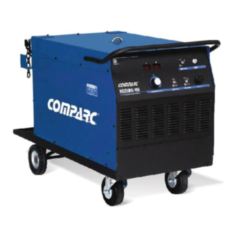
Comparc DELTA MIG 300 User manual

TABLE OF CONTENTS
ARC WELDING SAFETY PRECAUTIONS ...............................................................................i
SECTION 1 -- SAFETY SIGNAL WORDS ................................................................................1
SECTION 2 -- SPECIFICATIONS .............................................................................................1
2 - 1. Volt-AmpereCurves..........................................................................................................................1
2 - 2. DutyCycle.......................................................................................................................................2
SECTION 3 -- INSTALLATION .................................................................................................2
3 - 1. Selectingalocationandmovingweldingpowersource ......................................................................2
3 - 2. Installingworkclamp ........................................................................................................................3
3 - 3 Installing welding gun (Welding gun not included) ......................................................................3
3 - 4. Remote-14receptacleinformation .....................................................................................................3
3 - 5. Shielded gasconnections................................................................................................................3
3 - 6. Spoolwireinstallation.......................................................................................................................4
3 - 7. Settinggunpolarityforwiretype .......................................................................................................4
3 - 8. Selecting alocationandconnecting input power...............................................................................5
3 - 9. Threading weldingwire... .................................................................................................................6
SECTION 4 -- OPERATION ......................................................................................................7
4 - 1. Locationof controlsinweldingpowersource .....................................................................................7
4 - 2. Safetyequipment .............................................................................................................................7
4 - 3. Gunconnector .................................................................................................................................7
4 - 4. ReceptacleRC14. ............................................................................................................................7
4 - 5. Input powerswitch...........................................................................................................................8
4 - 6. Voltageadjustcontrol.......................................................................................................................8
4 - 7. Wirespeedcontrol ...........................................................................................................................8
4 - 8. Trigger modeselector......................................................................................................................8
4 - 9. Digitalvoltmeter andammeter..........................................................................................................8
4 - 10. Selectorof spot ................................................................................................................................9
4 - 10. OperationsequenceforGMAW,FCAW,SAW andCAC-A ................................................................9
SECTION 5 -- MAINTENANCE AND TROUBLESHOOTING ................................................10
5 - 1. Routinemaintenance......................................................................................................................10
5 - 2. Changingcontacttip ......................................................................................................................10
5 - 3. Circuit breakersCB1andCB2 .......................................................................................................10
5 - 4. Unitoverload ..................................................................................................................................10
5 - 5. Troubleshootings............................................................................................................................11
SECTION 6 -- ELECTRICAL DIAGRAM.................................................................................12
SECTION 7 -- PARTS LIST ....................................................................................................13
7 - 1. Mainassembly...............................................................................................................................16
WARRANTY

i
ARC WELDING SAFETY PRECAUTIONS
WARNING
PROTECT YOURSELF AND OTHERS FROM POSSIBLE SERIOUS INJURY OR DEATH. KEEP CHILDREN AWAY. PACEMAKER
WEARERS KEEP AWAY UNTIL CONSULTING YOUR DOCTOR.
In welding, as in most jobs, exposure to certain hazards occurs. Welding is safe when precautions are taken. The safety information given
below is only a summary of the more complete safety information that will be found in the Safety Standards. Read and follow all Safety
Standards.
HAVE ALL INSTALLATION, OPERATION, MAINTENANCE, AND REPAIR WORK PERFORMED ONLY BY QUALIFIED PEOPLE.
ARC WELDING can be hazardous.
ELECTRIC SHOCK can kill.
Touching live electrical parts can cause fatal shocks
or severe burns. The electrode and work circuit is
electrically live whenever the output is on. The input
power circuit and machine internal circuits are also
live when power is on. In semiautomatic or automatic
wire welding, the wire, wire reel, drive roll housing,
and all metal parts touching the welding wire are electrically live.
Incorrectly installed or improperly grounded equiment is a hazard.
1.- Do not touch live electrical parts.
2.- Wear dry, hole-free insulating gloves and body protection.
3.- Insulate yourself from work and ground using dry insulating
mats or covers.
4.- Disconnect input power or stop engine before installing or
servicing this equipment.
5.- Properly install and ground this equipment according to this
Owner's Manual and national, state, and local codes.
6.- Turn off all equipment when not in use.
7.- Do not use worn, damaged, undersized, or poorly spliced cables.
8.- Do not wrap cables around your body.
9.- Ground the workpiece to a good electrical (earth) ground.
10.- Do not touch electrode while in contact with the work (ground)
circuit.
11.- Use only well-maintained equipment. Repair or replace damaged
parts at once.
12.- Wear a safety harness to prevent falling if working above floor
level.
13.- Keep all panels and cover securely in place.
ARC RAYS can burn eyes and skin;
NOISE can damage hearing.
Arc rays from the welding process produce intense
heat and strong ultraviolet rays that can burn eyes and
skin. Noise from some processes can damage hearing.
1.- Wear a welding helmet fitted with a proper shade
of filter (see ANSIZ49.1 listed in Safety Standards) to protect
your face and eyes when welding or watching.
2.- Wear approvedsafety glasses. Side shields recommended.
3.- Use protective screens or barriers to protect others from flash and
glade; warn others not to watch the arc.
4.- Wear protective clothing made from durable, flame- resistant mate
rial (wool and leather) and foot protection.
5.- Use approved ear plugs or ear muffs if noise level is high.
FUMES AND GASES can be hazardous
to your health.
Welding produces fumes and gases. Breathing these
fumes and gases can be hazardous to your health.
1.- Keep your head out of the fumes. Do not breath the fumes.
2.- If inside, ventilate the area and / or use exhaust at the arc to remove
welding fumes and gases.
3.- If ventilation is poor, use an approved air-supplied respirator.
4.- Read the Material Safety Data Sheets (MSDSs) and the
manufacturer´s instruction for metal, consumables, coatings, and
cleaners.
5.- Work in a confined space only if it is well ventilated, or while wearing
an air-supplied respirator. Shielding gases used for welding can
displace air causing injury or death. Be sure the breathing air is safe.
6.- Do not weld in locations near degreasing, cleaning, or spraying
operations. The heat and rays of the arc can react with vapors to
form highly toxic and irritating gases.
7.- Do not weld on coated metals, such as galvanized, lead, or cadmium
plated steel, unless the coating is removed from the weld area, the
area is well ventilated, and if necessary, while wearing an air-
supplied respirator. The coatings and any metals containing these
elements can give off toxic fumes if welded.
WELDING can cause fire orexplosion.
Sparks and spatter fly off from the welding arc. The
flying sparks and hot metal, weld spatter, hot workpiece,
and hot equipment can cause fires and burns. Acciden-
tal contact of electrode or welding wire to metal objects
can cause sparks, overheating, or fire.
1.- Protect yourself and others from flying sparks and hot me-
tal.
2.- Do not weld where flying sparks can strike flammable material.
3.- Remove all flammables within 35ft (10.7 m) of the welding arc. If
this is not possible, tightly cover them with approved covers.
4.- Be alert that welding sparks and hot materials from welding can
easily go through small cracks and openings to adjacent areas.
5.- Watch for fire, and keep a fire extinguisher nearby.
6.- Be aware that welding on a ceiling, floor, bulkhead, or partition can
cause fire on the hidden side.
7.- Do not weld on closed containers surch as tanks or drums.
8.- Connect work cable to the work as close to the welding areas as
practical to prevent welding current from traveling long, possibly
unknown paths and causing electric shock and fire hazards.
9.- Do not use welder to thaw frozen pipes.
10.- Remove stick electrode from holder or cut off welding wire at
contact tip when not in use.
11.- Wear oil-free protective garments such as leather gloves, heavy
shirt, cuffless trousers, high shoes, and a cap.

ii
FLYING SPARK AND HOT METAL can
cause injury
Chipping and grinding cause flying metal . As welds
cool, they can throw off slag.
CYLINDERS can explode if damaged.
Shieldinggas cylinders contain gas under high pressure.
If damaged, a cylinder can explode. Since gas cylinders
are normally part of the welding process, be sure to
treat them carefully.
1.- Protect compressed gas cylinders from excessive heat, mechanical
shocks, and arcs.
2.- Install and secure cylinders in an upright position by chaining them
to a stationary support or equipment cylinder rack to prevent falling
or tipping.
3.- Keep cylinders away from any welding or other electrical circuits.
4.- Never allow a welding electrode to touch any cylinder.
5.- Use only correct shielding gas cylinders, regulators, hoses, and
fittings designed for the specific application; maintain them and
associated parts in good condition.
6.- Turn face away from valve outlet when opening cylinder valve.
7.- Keep protective cap in place over valve except when cylinder is in
use or connected for use.
8.- Read and follow instructionson compressed gas cylinders, associated
equipment, and CGA publication P-1 listed in Safety Standards.
ENGINES can be hazardous.
WARNING
ENGINE EXHAUST GASES can kill.
Engines produce harmful exhaust gases.
1.- Use equipment outside in open, well-ventilated
areas.
2.- If used in a closed area, vent engine exhaust outside and away from
any building air intakes.
ENGINE FUEL can cause fire or
explosion.
Engine fuel is highly flammable.
1.- Stop engine before checking or adding fuel.
2.- Do not add fuel while smoking or if unit is near any sparks or open
flames.
3.- Allow engine to cool before fueling. If possible, check and add fuel
to cold engine before beginning job.
4.- Do not overfill tank - allow room for fuel to expand.
5.- Do not spill fuel. If fuel is spilled, clean up before starting engine.
MOVING PARTS can cause injury.
Moving parts, such as fans, rotors, and belts can cut
fingers and hands and catch loose clothing.
1.- Keep all doors, panels, covers, and guards closed
and securely in place.
2.- Stop engine before installing or connecting unit.
3.- Have only qualified people remove guards or covers for maintenance
and troubleshooting as necessary.
4.- To prevent accidental stating during servicing, disconnect negative
(-) battery cable from battery.
5.- Keep hands, hair, loose clothing, and tools away from moving parts.
6.- Reinstall panels or guards and close doors when servicing is finished
and before starting engine.
SPARKS can cause BATTERY GA-
SES TO EXPLODE; BATTERY ACID
can burn eyes and skin.
Batteries contain acid and generate explosive gases.
1.- Always wear a face shield when working on a
battery.
2.- Stop engine before disconnecting or connecting battery cables.
3.- Do not allow tools to cause sparks when working on a battery.
4.- Do not use welder to charge batteries or jump start vehicles.
5.- Observe correct polarity (+ and -) on batteries.
STEAM AND PRESSURIZED HOT
COOLANT can burn face, eyes, and
skin.
The coolant in the radiator can be very hot and under
pressure.
1.- Do not remove radiator cap when engine is hot. Allow engine to cool.
2.- Wear gloves and put a rag over cap area when removing cap.
3.- Allow pressure to escape before completely removing cap.
1.- Wear approved face shield or safety goggles. Side shields
recommended.
2.- Wear proper body protection to protect skin.

iii
CONSIGNES DE SÉCURITÉ POUR LE SOUDAGE À L’ARC
MISE EN GARDE
SE PROTÉGER ET PROTÉGER LESAUTRES CONTRE LES BLESSURES GRAVES VOIRE MORTELLES. TENIR LES ENFANTS ÀL’ÉCRT. LES PERSONNES
QUIPQRTENTUNSTIMULATEURCARDIAQUENEDOIVENTPASNONPLUSS’APPROCHERDUPOSTEDESOUDAGE,AMOINSD’AVOIRCONSULTUNMÉDECIN.
Le soudage, comme la plupart des travaux, présente certains dangers. Par contre, le soudage peut être effectué en toute sécurité quand on prend les mesures
qui s’imposent. Les consignes de sécurite données ci-après ne font que résumer I’information contenue dans les normes de sécurité énumérées à la page
suivante. Lire et respecter toutes ces normes de sécurité.
L’INSTALLATIONL’UTILISATIONL’ENTRETIENETLESRÉPARATIONSNEDOIVENTÊTRECONFIÉSQU’ÀDESPERSONNESQUALIFIÉES.
UNCHOCÉLECTRIQUEpeuttuer.
Unsimple contact avecdes pieces lectriques peut provoquer
une electrocution ou des blessures graves. L’électrode et
le circuit de soudage sont sous tensiuon dès que I’appareil
est sur ON. Le circuit d’entrée et les circuits intemes de
I’appareil sont également sous tension à ce moment-là. En
soudagesemi-automatiqueouautomatique, lefil,ledévidoir,
le logement des galets d’entraînement et les pièces
métalliques en contact avec le fil de soudage sont sous
tension. Des matériels mal installés ou mal mis à la terre
présentent un danger.
1. Ne jamais toucher les pièces électriques sous tension.
2. Porter des gants et des vêtements de protection secs ne comportant
pas de trous.
3. S’isoler de la pièce et de la terre au moyen de tapis ou d’autres moyens
isolants suffisamment grands pour empêcher le contact physique
éventuel avec la pièce ou la terre.
4. CouperI’alimentationouarrêter lemoteuravantdeprocéderàI’installation,
à la réparation ou à I’entretien de I’appareil.
Déverrouiller I’alimentation selonla norme OSHA29 CFR 1910.147 (voir
normes de sécurité).
5. Installer et mettre à la terre correctement cet appareil conformément à
sonmanuel d’utilisationetaucodes nationaux,provinciauxetmunicipaux.
6. Toujours vérifier la terre du cordon d’alimentation - Vérifier et s’assurer
que le fil de terre du cordon d’alimentation est bien raccordé à la bome
de terre du sectionneur ou que la fiche du cordon est raccordée à une
prise correctement mise à la terre.
7. En effectuant les raccordements d’entrée fixer d’abord le conducteur de
mise à la terre approprié et contre-vérifier les connexions.
8. Vérifier fréquemment le cordon d’alimentation pour voir s’il n’est pas
endommagé ou dénudé - remplacer le cordon immédiatement s’il est
endommagé - un câble dénudé peut provoquer une électrocution.
9. Mettre I’appareil hors tension quand on ne I’utiiise pas.
10. Ne pas utiliser des câbles usés, endommagés, de grosseur insuffisante
ou mal épissés.
11. Ne pas enrouler les câbles autour du corps.
12. Si la pièce soudée doit être mise à la terre, le faire directement avec un
câble distinct -ne pas utiliser le connecteur de pièce ou le câble de retour.
13. Ne pas toucher I’électrode quandon est en contact avec la pièce, la terre
ou une électrode provenant d’une autre machine.
14. N’utiliser qu’un matériel en bonétat. Réparer ouremplacer sur-le-champ
les pièces endommagées. Entretenir I’appareil conformément à ce
manuel.
15. Porter un harnais de sécurité quand on travaille en hauteur.
16. Maintenir solidement en place tous les panneaux et capots.
17. Fixer le câble de retour de façon à obtenir un bon contact métal-métal
avec la pièce à souder ou la table de travail, le plus près possible de la
soudure.
LE RAYONNEMENT DE L’ARC peut brûler les yeux et la
peau.LeBRUITpeut endommager I’ouïe;lesPROJECTIONS
DELAITIEROULESÉTINCELLESpeuventblesserlesyeux.
L’arc de soudage produit des rayons visibles et invisibles
intenses (ultraviolets et infrarouges) qui peuvent brûler les
yeux et la peau. Le bruit produit par certains procédés peut
endommager I’ouïe. Des projections de métal ou de laitier
sontproduitesparlepiquage,lemeulageoulerefroidissement
des soudures.
BRUIT
1. Utiliser des bouche-oreilles ou des serre-tête antibruit approuvés si le
niveau de bruit est élevé.
RAYONNEMENTDEL’ARC
2. Porter un masque à serre-tête muni d’un verre filtrant de nuance
appropriée pour protéger levisage et les yeuxquand on soude ouobserve
la travail de soudage (voir les normes ANSIZ49.1 et Z87.1données sous
la rubrique Principales normes de sécurité).
3. Porter des lunettes de sécurité approuvées avec écrans latéraux.
4. Utiliser des paravents ou des barrières de protection pour protéger les
personnes à proximité contre les coups d’arc et l’eblouissement; avertir
les autres personnes de ne pas regarder I’arc.
5. Porter des vêtements de protection en tissu ignifuge durable (laine et
cuir) et des chaussures de sécurité.
portant un appareil respiratoire à adduction d’air pur. Demander à un
observateur ayant reçu la bonne formation de toujours se tenir à
proximité. Les vapeurs et fumées de soudage peuvent déplacer I’air
et abaisser le niveau d’oxygène et causer des blessures graves voire
mortelles. S’assurer que I’air est propre à la respiration.
6. Ne pas souder à proximité d’opérations de dégraissage, de nettoyage
ou de pulvérisation. La chaleur et les rayons de I’arc peuvent réagir avec
les vapeurs pour former des gaz hautement toxiques et irritants.
7. Ne pas souder sur des métaux revêtus comrne I’acier galvanisé, au
plomb ou cadmié à moins que la pièce n’ait été entièrement décapée,
que le poste de travail soit bien ventilé. S’il y a lieu, porter un appareil
respiratoire à adduction d’air pur. Les revêtements et les métaux qui
contiennent de tels éléments peuvent dégager des vapeurs toxiques lors
du soudage.
LESVAPEURSETLESFUMÉESpeuvent êtredangereuses
pour la santé.
Le soudage produit des vapeurs et des fumées qu’il est
dangereux de respirer.
1. Garder la tête à I’exterieur des vapeurs et des fumées et
ne pas les respirer.
2. A I’intérieur, ventiler le poste de travail ou utiliser un dispositif placé au
niveau de I’arc pour évacuer les vapeurs et fumées de soudage.
3. Si la ventilation est mauvaise, utiliser un appareil respiratoire à adduction
d’air pur approuvé.
4. Consulter les fiches signalétiques et les consignes du fabricant relatives
au métaux, produits d’apport, revêtements, nettoyants et dégraissants.
5. Ne travailler dans un espace confiné que s’il est bien ventilé, ou en
LES BOUTEILLES peuvent exploser si elles sont
endommagées.
Les bouteilles contenant des gaz de protection sont à haute
pression. Une bouteille endommagée peut exploser. Étant
donné que les bouteilles de gaz font normalement partie du
matériel de soudage, les traiter avec le plus grand soin.
1. Protéger les bouteilles de gaz comprimé contre la chaleur intense, les
chocs, le laitier, les flammes nues, les étincelles et I’arc.
2. Placer les bouteilles à la verticale en les fixant à un support fixe ou à
un chariot pour éviter qu’elles ne tombent ou ne basculent.
3. Tenir les bouteilles à I’écart du poste de soudage ou d’autres circuits
électriques.
4. Ne jamais poser un chalumeau soudeur sur une bouteille de gaz.
5. Ne jamais laisser une électrode de soudage toucher une bouteille.
6. Ne jamais souder sur une bouteille sous pression: elle exploserait.
7. N’utiliser que des bouteilles de gaz de protection, des détendeurs, des
tuyaux souples et des raccords appropriés conçus pour I’application
particulière; conserver ces matériels et leurs pièces en bon état.
8. Éloigner le visagede la sortie du robinet de la bouteille quand on I’ouvre.
9. Replacer le chapeau sur la bouteille après utilisation.
10. Lire et suivre les consignes relatives aux bouteilles de gaz comprimé,
au matériel connexe ainsi que la publication P-1 de la CGA donnée sous
la rubrique Principales normes de sécurité.
LE SOUDAGE À L’ARC peut être dangereux.

MISE EN GARDE
iv
LESOUDAGE peut causer un incendie ou une explosion.
Ne pas souder sur des récipients fermés comme des
réservoirs, des fûts ou des tuyaux: ils peuvent exploser.
L’arc desoudage peut produiredes étincelles. Des étincelles,
une pièce chaude et un matériel chaud peuvent provoquer
des incendies et des blessures. Le contact accidentel de
I’électrode sur des objets métalliques peut produire des
étincelles,I’explosion,lasurchauffeouunincendie.S’assurer
que le lieu ne présente pas de danger avant d’effectuer le
soudage.
1. Se protéger et protéger les personnes à proximité des étincelles et du
métal chaud.
2. Ne pas souder dans un endroit où les étinceiles peuvent atteindre des
matériaux inflammables.
3. Enlever toutes les matières inflammables dans un rayon de moins de
10 m de I’arc. Si cela n’est pas possible, bien les recouvrir en utilisant
des bâches approuvées.
4. Prendre gardeque les étincelles et les projections ne pénétrent dans des
zones adjacentes en s’infiltrant dans des petites fissures et ouvertures.
5. Prendre garde aux incendies et toujours avoir un extincteur à proximité.
6. Se rappeler que si I’on soude sur un plafond, un plancher, une cloison
ou autre, le feu peut prendre de I’autre côté.
7. Ne pas souder sur des récipients fermés comme des réservoirs, des fûts
ou des tuyaux à moins qu’ils ne soient préparés de façon appropriée
conformément à la norme F4.1 de I’AWS (voir la rubrique Principales
normes de sécurité).
8. Raccorder le câble de retour à la pièce, le plus près possible de la zone
de soudage, pour empêcher que le courant de soudage ne suive une
trajectoire longue et éventuellement inconnue et qu’il ne provoque des
risques d’électrocution et d’incendie.
9. Ne pas utiliser le chalumeau soudeur pour dégeler des tuyaux.
10. Enlever I’électrode enrobée du porte-électrode ou couper le fil de
soudage au ras du bec contact quand on ne I’utilise pas.
11. Porter des vêtements de protection non huileux comme des gants en
cuir, une chemise épaisse, des pantalons sans revers, des chaussures
montantes et un casque.
12. Ne pas porter des matières combustibles sur soi commeun briquet àgaz
ou des allumettes quand on soude.
LES MOTEURS peuvent présenter un danger.
LESGAZ D’ÉCHAPPEMENT DES MOTEURS peuvent être
mortels.
Les moteurs produisent des gaz d’échappement nocifs.
1. Utiliser le matériel à I’extérieur, dans des lieux ouverts et bien ventilés.
2. Si onutiliseunmoteurdansunlocalfermé,évacuerlesgazd’échappement
à I’extérieur et loin des prises d’air du bâtiment.
LECARBURANTpeutprovoquerunincendieouuneexplosion.
Le carburant est hautement inflammable.
1. Arrêter le moteur et le laisser refroidir avant de vérifier
le niveau de carburant ou de refaire le plein.
2. Ne pas fumer en faisant le plein ou si I’appareil se trouve à proximité
d’étincelles ou de flammes nues.
3. Ne pas remplir le réservoir à ras bord: prévoir de I’espace pour la
dilatation du combustible.
4. Ne pas renverser du carburant. Si on renverse du carburant, nettoyer
les lieux avant de faire démarrer le moteur.
LES PIÈCES EN MOUVEMENT peuvent causer des
blessures.
Les pièces en mouvement comme les ventilateurs, les
rotors et les courroies peuvent couper les doigts et les mains
et happer les vêtements amples.
1. S’assurer queles portes, les panneaux, les capots et les
protecteurs sont bien fermés et bien à leur piace.
2. Arrêter le moteur avant de mettre en place ou de raccorder un dispositif.
3. Seules des personnes qualifiées doivent démonter les protecteurs ou
les capots pour faire I’entretien ou les réparations nécessaires.
4. Pour empêcher un démarrage accidentel d’unsystémependant I’entretien
ou les réparations, débrancher le câble négatif (-) de la batterie.
5. Éloigner les mains, les cheveux, les vêtements amples et les outils des
pièces en mouvement.
6. Replacer les capots ou les protecteurs et refermer les portes une fois
I’entretien et les réparations terminés et avant de faire démarrer le
moteur.
2. Arrêter le moteur avant de brancher ou de débrancher les câbles de la
batterie.
3. Ne pas faire des étincelles avec les outils quand on travaille sur une
batterie.
4. Nepas utiliser lasource de courant desoudagepour charger les batteries
ou pour faire démarrer un véhicule.
5. Ne pas intervertir la polarité des batteries.
LES ÉTINCELLES peuvent faire EXPLOSER LE GAZ DES
BATTERIES; L’ÉLECTROLYTE peut brûler la peau et les
yeux.
Les batteries contiennent un produit acideet dégagent des
vapeurs explosives.
1. Toujours porter un écran facial quand on travaille sur une batterie.
LAYAPEURETLELIQUIDEDEREFROlDISSEMENTBRÛLANT
SOUS
PRESSION peuvent brûler la peau et les yeux.
II vaut mieux vérifier le niveau du liquide de refroidissement
quand le moteur est froid afin d éviter les brûlures.
1. Si I’on doitvérifier le niveau quandle moteur est chaud,suivre les étapes
2 et 3.
2. Porter des lunettes de sécurité et des gants et placer un chiffon sur le
bouchon.
3. Tournerlentementle bouchon et laisser lapressions’échapper lentement
avant d’enlever complètement le bouchon.
PRINCIPALES NORMES DE SÉCURITÉ
Safety in Welding and Cutting, norme ANSI Z49.1, de I’American Welding
Society, 550 N.W. Lejeune Rd, Miami FL 33126
Safety and Health Sandards, OSHA 29 CFR 1910, du Superintendent of
Documents, U.S. Government Printing Office, Washington, D.C. 20402.
Recommended Safe Practice for the Preparation for Welding and Cutting of
Containers That Have Held Hazardous Substances, norme AWS F4.1. de
I’American Welding Society, 550 N,W. Lejeune Rd, Miami FL 33126
National Electrical Code, NFPA Standard 70, de la Nationai Fire Protection
Association, Batterymarch Park, Quincy, MA 02269.
Safe Handling of Compressed Gases in Cylinders, CGA Pamphlet P-1, de
la Compressed Gas Association, 1235 Jefferson Davis Highway, Suite 501,
Arlington, VA 22202.
Règles de sécurité en soudage, coupage et procédés connexes, norme CSA
W117,2, de I’Association canadiennede normalisation, vente denormes,178
Rexdale Boulevard, Rexdale (Ontario) Canada M9W 1R3.
Safe Practices For Occupation And Educational Eye And Face Protection,
normeANSIZ87.1, de I’AmericanNational StandardsInstitute, 1430 Broadway,
New York, NY 10018.
Cutting and Welding Processes, norme NFPA 51B, de la National Fire
Protection Association, Batterymarch Park, Quincy, MA 02269.

* Including running gear and lifting eye.
SECTION 2 - SPECIFICATIONS
SECTION 1 - SAFETY SIGNAL WORDS
MODEL OUTPUT
TYPE
RATED
OUTPUT AT
100% D.C. OVERALL
DIMENSIONS
AMPERES INPUT AT RATED LOAD
OUTPUT, 60 Hz THREE-PHASE
230 A
26 VDC
WEIGHT:NET
(SHIP)
230 V 460 V kW kVA
MAX. OPEN
CIRCUIT
VOLTAGE
VOLTAGE
RANGE
300 AMP DC / CV 14-30 VDC 30.6 A 15.3 A 7.7 12.5
297 lb
(135 Kg)
(304 lb
(138 KG))
DEPTH:
965 mm
WIDHT:
550 mm
*HEIGHT:
780 mm
80 VDC
WARNING
CAUTION
IMPORTANT: Statements identify special instructionsnecessaryforthemostefficientoperationofthisequipment.
WARNING statements identify procedures or practices which must be followed to
avoid seriuos personal injuryor loss of life.
CAUTIONstatementsidentifyproceduresorpracticeswhichmustbefollowedtoavoid
minor personal injury or damage to this equipment.
Thefollowingsafetyalertsymbolandsignalwordsareusedthroughoutthismanualtocallattentiontoandidentifydifferent
levelsof hazardandspecialinstructions.
575 V
12.2 A
2-1 VOLT - AMPERE CURVES.
FIGURE2-1 VOLT-AMPERECURVES
Thevolt-amperecurvesshowtheminimumandmaximumvoltage and amperage output capabilities of thewelding
power source. Curvesof other settingsfall betweenthe curvesshown.
AMPERES DC
VOLTS DC
0
5
10
15
20
25
30
35
40
45
50
55
60
65
70
75
80
0 10 20 30 40 50 60 70 80 90 100 110 120 130 140 150 160 170 180 190 200 210 220 230 240 250 260 270 280 290 300
1

SECTION 3 - INSTALLATION
3.1 SELECTING A LOCATION AND MOVING WELDING POWER SOURCE.
Figure 3-2 Locationandmovingwelding powersource.
Rear
Left
Front
Right Up
1
2
1.- 10 in (254 mm) open space
on right side and left of unit
for good airflow.
Definition
DutyCycle ispercentageof 10 minutesthat unit
canweldatratedloadwithoutoverheating.
WELDING LONGERTHANRATEDDUTY CYCLEcan damageunit or gun and void
warranty. Do not weld at rated over output longer than shown duty cycle chart.
CAUTION
2-2 DUTY CYCLE.
6 Minutes Welding 4 Minutes Resting Continuous Welding
Overheating
0
15
A or V
OR
ReduceDuty Cycle
Minutes
60% Duty CycleAt 300Amperes 100% Duty CycleAt 2 0Amperes
3
% DUTY CYCLE
WELD AMPERAGE
20
100
150
200
250
300
35
60
90
40
70
100 %30
50
80
232
10
0
MINUTES

3
3-3 INSTALLING WELDING GUN (WELDING GUN NOT INCLUDED)
1 Drive Assembly
2 Gun Securing Knob
3 Gun End
Loosen securing knob. Insert gun
end through opening until it bottoms
against drive assembly. Tighten
knob.
4 Gun Trigger Plug
Insert plug into receptacle, and
tighten threaded collar.
Close door.
Figure 3-3 Workclamp.
3-2 INSTALLING WORK CLAMP.
9.5, 11.1 mm(3/8, 7/16")
1.-WorkCablefromUnit.
2.- Contact Piece.
3.-Screw.
4.-WorkClamp.
5.-Washer.
Tools Needed
3
1
5
2
4
Figure4-4 Shieldedgasconnection.
WARNING SEE SAFETY SIGNALS AT THE BEGINING THIS MANUAL
3-5. SHIELDED GAS CONNECTIONS.
1
2
3
4
5
6
Be sure gas cylinder is held to running gear, wall, or other stationary support
so cylinder can not fall and break off valve.
1.- CAP.
2.- CYLINDER VALVE.
Remove cap, stand to side of valve, and open valve slightly. Gas flow blows
dust and dirt from valve. Close valve.
3.- CYLINDER.
4.- REGULATOR /FLOWMETER.
5.- GAS HOSE CONNECTION.
6.- FLOW ADJUST.
Typical flow rate is 20 cfh ( Cubic Feet per Hour).
28.5, 15.8mm (1-1/8",5/8")
Toolsneeded:
OUTPUT
(CONTACTOR)
INFORMATION
Socket
REMOTE-14
A
B
I
J
G
K
24 V a.c. Protected by CB2 (10 Amperes).
Contact closure to "A" completes 24 V a.c. contactor control circuit.
120 V a.c. Protected by CB1(10 Amperes).
Contact closure to "I" completes 120 V a.c. contactor control circuit.
Circuit common for 24 and 120 V a.c. circuits.
Chassis common.
NOTE: Remaining sockets are not used
3-4. REMOTE-14 RECEPTACLE INFORMATION.
G N D
1
2
4
3

4
3-6. SPOOL WIRE INSTALLATION.
FIGURE 4-3 SPOOLWIREINSTALLATION.
For 8" and 12" (standard) wire spools
turn unit off anddisconnect it.
1.- Hub spool.
2.- Pin of Hub spool.
3.- Wire spool / Reel.
4.- Hud spool cap.
Turn the hub spool cap counter clockwise
andremoveit. Install thewirespool, be
sure the hub spool´s pin enters one of the
holesof thewire spool. Reinstall the hub
spool cap.
1
23
4
3-7. SETTING GUN POLARITY FOR WIRE TYPE
1 Polarity
Changeover Label
(Located Near Drive
Assembly)
Always read and follow manufac-
ture’s recommended polarity.
ShownAs Shipped – Set For Electrode
Positive (DCEP) For Solid Steel Or
Aluminum Wires (GMAW Process).
Wire DriveAssembly Lead
To Positive (+) Output Terminal
Work Clamp LeadTo
Negative (–) Output Terminal
GUN POLARITY
CHANGEOVER CONNECTIONS
Reverse Lead Connections– For Electrode
Negative (DCEN) For Flux Cored Wires
(FCAW Process). DriveAssembly
Becomes Negative
1
3/4, 11/16 in
REVERSE POLARITY
STRAIGHT POLARITY
LOW INDUCTANCE
LOW INDUCTANCE
HIGH INDUCTANCE
HIGH INDUCTANCE

5
3-8. SELECTING A LOCATION AND CONNECTING INPUT POWER
Have only quali?ed persons make this installation.
1 Jumper Link Label
2 Jumper Links
Move jumper links to match input voltage.
Reinstall wrapper.
1 in ( mm)
0 254
for air?ow
1
230 VOL 46 575
TS 0 VOLTS VOLTS
2
D
o not overtighten
jumper link nuts.
T
ools Nee
ded:
3/8 in
3/8 in
L1
L2
GND/PE
L3
GND/PE
Connect First
1 2 3 4 5 6 1 2 3 4 5 6 1 2 3 4 5 6 123456 123456 12345 6
1
2
3
4
5
6
1
2
3
4
5
6
1
2
3
4
5
6
L1
L2
L3
L1
L2
L3
L1
L2
L3
Check input voltage available at site.

6
3-9 THREADING WELDING WIRE
4
3
7
6
2
1
1 Wire
Spool
2 Welding Wire
3 Inlet Wire Guide
4 PressureAdjustment Knob
5 Drive Roll
6 Outlet Wire Guide
7 Gun Conduit Cable
Lay gun cable out straight.
Tools Needed:
6 in
(150 mm)
Hold
Wire tightly to keep it
from unraveling.
Open Pressure Assembly
Push Wire Thru Guides Into Gun,
Continue to Hold Wire
Pull and Holl Wire, Cut of End
Tighten
C T P ,
lose and ighten ressure
Assembly, nd et go of ire.a L W R G N C
emove un ozzle and ontact tip.
Turn On.
Size and ratings must comply with
applicable
Section 2-11). Install conductors in
conduitor equivalent into a deenergized line
L3
ools Nee
1
GND/PE
Connect First
WOOD
Press gun trigger until wire
comes out of gun. Reinstall
contact tip and nozzle
Feed wire to check drive roll pressure.
Tighten knob enough to prevent slipping. Cut off wire. Close
The door.

R
7
SECTION - 4 OPERATION
4-1 LOCATION OF CONTROLS IN WELDING POWER SOURCE.
CAUTION SEE SAFETY SIGNALS AT THE
BEGINING THIS MANUAL
REMOTE14
RECEPTACLE
AMMETER
WIRESPEED
CONTROL
GUN
TRIGGER
TORCH
CONNECTOR
MAIN
SWITCH
SPOT
SWITCH
SPOTTIME
CONTROL
VOLTMETER
ADJUSTMENT
VOLTAGE
2T/4TSELECTOR
FIGURE 4-2 SAFETYEQUIPMENT
3
21 1- Insulating Gloves.
2- Safety Glasses With Side Shields.
3- Welding Helmet.
Wear dry insulating gloves, safety glasses with side shields, and a welding
helmet with a correct shade of filter (see ANSI Z49.1).
Gun Connector. Connect gun into gun
receptacle until bottom and be sure be perfectly
tighten.
FIGURE 4-3 GUNCONNECTOR.
GUN TRIGGER
GUN
FIGURE 4-4 RECEPTACLE RC14.
RC14 RECEPTACLE. This connector is a receptacle for a gun spool. To connect this receptacle, align
keyway, insert plug, and tighten threaded collar.
Socket Information:
SOCKET A: 24 Volts AC, 10 Amperes, 60 Hz., respect G socket (common).
SOCKET B: Contact closure to pin A completes 24 Volts AC contactor control circuit
SOCKET G: Circuit common for 24 and 120 VAC circuit.
SOCKET I: 120 VAC respect socket G.
SOCKET J: Contact closure to pin I completes 120 VAC contactor control circuit.
SOCKET K: Common .
REMAINING SOCKETS ARE NOT USED.

FIGURE 4-7 WIRE SPEED CONTROL
1.-WIRESPEEDCONTROL.
Usethiscontroltoselectwirefeedspeedinspeedranges.
Turn in clock wise to increase speed. The numbers is a
percentagerespectamaximunratedspeed(900ipm)
1
FIGURE 4-8 TRIGGER MODE SELECTOR.
TRIGGER MODESELECTOR.Usethiscontroltoselectthe desired
triggermode.
Selectalways onetrigger mode:
1. 2T Trigger mode: When trigger is depressed, weld starts. When
trigger is released, weld stops.
2. 4T Trigger mode: When trigger is depressed, weld starts. When
triggerisreleased,weldremains.Afterdepressingandreleasing
the trigger for the second time, weld stops.
TRIGGER
FIGURE 4-9. DIGITAL VOLTMETER AND AMMETER
DIGITALVOLTMETERANDAMMETER.
With "contactor off". Voltmeter display PRESET voltage and ammeter is turn off.
With "contactor on". Voltmeter and ammeter display actual output voltage and
amperage, ammeter remains off if current is zero amperes.
While welding, the meters measure and display the output arc voltage and amperage.
once extinguished the arc, the digital meters retained the arc values approx 4 sec.,
subsequently shown PRESET value.
VOLTAGEADJUSTMENT
Use this control to set the arc voltage.
FIGURE 4-5 INPUT POWER SWITCH
INPUT POWER SWITCH.Place the power switch in ON
position energizes the welding power source. Place the
power switch in the OFF position the unit shuts down.
V
8
FIGURE 4-6 VOLTAGE ADJUST

FIGURE 4-10. SPOT TIME CONTROL
FUNCTION SELECTOR: Place the switch in the position ( I ) activate the function:
1.- Dotting: Welding by time intervals, the duration of each interval (from when the torch trigger
is pressed) will depend on the position pre-set in the control of the spot time.
SPOT TIME CONTROL. This control allows you to adjust the tapping time (duration of
the operation or welding interval) from 0.5 to 4 seconds. Turning the knob clockwise
increases the time. The scale of the control is calibrated in percentage and does not
indicate the interval time.
Install and
connect the
equipment
Turn On Wire feeder
and Power Source
Put On
safety
equipment
Install and
prepare Flux
system
Install and
prepare
wire feeder
Set Control Turn On Flux
system Beging welding
Readjsut
controls and
begin welding
Open
gas
valve
Turn On Wire
feeder and Power
Source
Put On
safety
equipment
Install and
prepare
wire feeder
Install and
connect the
equipment
Readjsut
controls and
begin welding
Put On
safety
equipment
Install and
prepare
wire feeder
Install and
connect the
equipment
Turn On Wire
feeder and Power
Source
Set Controls
Put On
safety
equipment.
Select
coat
electrode
Connect
compreser air
system
Inssert electrode into
torch Supply
compresed air Turn On Power
Source Start cutting or
gouging
Install and
connect the
equipment
AIR CUTTING AND GOUGING PROCESS (CAC-A)
9
FIGURE 4-11 OPERATION SEQUENCE FOR GMAW, FCAW, SAW, CAC-A
SUBMERGED ARC PROCESS (SAW)
FLUX CORED ARC WELDING PROCESS (FCAW)
SOLID WIRE PROCESS (GMAW)

SECTION - 5
MAINTENANCE &TROUBLESHOOTING
5-1 ROUTINE MAINTENANCE
WARNING SEE SAFETY SIGNAL AT THE BEGINING THIS MANUAL
TIME
Above normal equipment use: Check all labels ( see 6 month entry ), repair any damaged
insulation or replace holder or work cable, clean internal parts ( see 6 month entry ), clean and
tighten connections at holder cable and work clamp.
Every month
Every 3 months
Every 6 months
MAINTENANCE
Replace Unreadable Labels, Tape Or Replace Cracket Cables, Clean And Tighten Weld
Terminals, Replace Cracket Parts.
Blow Out Or Vacuum inside,During Heavy Service Clean Monthly.
FIGURE5-1.CHANGINGCONTACTTIP.
Turnoff anddisconnecttheunit.
1.- NOZZLE.
2.-CONTACTTIP.Cut wire remaining
ofthecontacttip,removeNozzle,remove
the contact tip and install one new.
Reinstallnozzle.
ToolsNeeded
2
1
5-2 CHANGING CONTACT TIP.
5-3 CIRCUIT BREAKERS CB1 AND CB2
1Circuit Breaker CB2
CB2 protects Remote14 receptacle ( RC3)
fromoverload.
2Circuit Breaker CB1
If CB1opens,wirefeedingstops.
3WeldingGun(NotIncluded)
Check gun liner for blockageor kinks.
4WireDriveAssembly
Checkforjammedwire,bindingdrivegear
ormisaligneddriverolls.
Allowcoolingperiodandresetbreaker.
Close thedoor
5-4 UNIT OVERLOAD
If unit is used beyond capacity (excessive wire feed, shorted output, etc.), wire feeds but is not energized.
Release gun triggerto reset this condition.
10
3
1
2
4

Trouble Remedy
Be sure Powerswitch is On
Replace building line fuse or reset circuit breaker if open
Reset circuit breakerCB1
Secure gun trigger connections
Have Factory Authorized Service Agent check Power switch.
Have Factory Authorized Service Agent check all board
Thermostat TP1 open (overheating). Allow fan to run; the
Connect work clamp to get good metal to metal contact.
Replace contact tip
An overload condition occurred. Release gun trigger
Have Factory Authorized Service Agent check main control board
Connect unit to proper input voltage orcheck for low line voltage
Check input voltage jumper links and correct position if necessary
Have Factory Authorized Service Agent check main control board.
Readjust front panel settings.
Change to correct size drive rolls
Readjust drive roll pressure
Replace inlet guide, contact tip, and/or liner if necessary
Check position of input jumper links
Have Factory Authorized Service Agent check main control board.
Reset circuit breaker CB1
Turn Wire Speed control to higher setting.
Clear obstruction in gun contact tip or liner.
Readjust drive roll pressure.
Change to correct size drive rolls.
Rethread welding wire.
Check gun trigger and leads. Repair or replace gun if necessary.
Have Factory Authorized Service Agent check main control board.
No weld output;
wire does not feed.
No weld output;
wire feeds.
Low weld output.
Low, high, or erratic
wire speed.
No wire feed.
5-5 TROUBLESHOOTINGS.
11

12
SECTION - 6 ELECTRICAL DIAGRAM
Figure 6-1 Electrical Diagram
DE-0160
REV. 0
1
1
1
2
2
2
3
3
3
4
4
4
5
5
5
6
6
6
F1
F2
F3
F4
F5
F6
F7
111
2 2 2
3 3
575 VOLTS AC
3
4 4 4
5 5 5
666
1
1
1
2
2
2
3
3
4
6
0
V
O
L
T
S
A
C
3
4
4
4
5
5
5
6
6
6
1 1
1
2 2
2
3 3
230 VO LTS AC
3
4 4
4
5 5
5
6 6
6

13
SECTION - 7 PARTS LIST
7-1 MAIN ASSEMBLY
ITEMNo. PARTNO. DIA.MKGS DESCRIPTION QUANTITY
1 PC2023 BASE 1
2 PR0922 WHEELSREAR 1
3 MR05740 SWIVELCASTER 2
4 PF0738 PANEL, FRONT 1
5 PB1770 BAFFLECENTRAL 1
6 PS1365 BRACKET 1
7 PT3614 TC1 TERMINALINPUTCONNECTIONS 1
8 PM0822 CHOPPER MODULECHOPPERMCH300.015 1
9 PB1793 BAFFLE 1
10 PC2025 COVER, FIX 1
11 PC2027 COVER, REMOVABLE 1
12 PC2032 PANEL,COVERCOMPLEMENT 1
13 MV01060 MV FAN 1
14 PE0763 Z1 ESTABILIZERASSEMBLY 1
PN0187 CORE 1
PB1803 COIL 1
PC2037 HEADCORE 1
15 PT3609 T1 TRANSFORMER, POWERMAIN 1
PN0186 CORE 1
PB2384 COILPRIM-SECTYPE"A" 1
PB2385 COILPRIM-SECTYPE"B-C" 1
PC2034 HEADCORE 1
16 PT2408 PANEL,REAR 1
17 PR0464 BRACKET, BOTTLERETAINER 1
18 PT2426 PC5 PCB, FILTER 1
19 PT2086 PC 2 CONTROLCARD, CHOPPER 1
20 PT2087 PC 1 CONTROLBOARD, PCB 1
21 MF02312 F1, F2,F3 FUSE,0.5A, typ. AGC-1/2, 250V fastaction 3
22 MF02311 F4 FUSE,2A, typ. AGC-2, 250V fastaction 1
23 MF02313 F5 FUSE,10A, typ.AGC-10, 250V fastaction 1
24 MB05897 FUSEBASE 5
25 MF02313 F6, F7 FUSE,2.5A, typ CC 600Vac/300Vdcdelayed action 2
26 MB05896 FUSEBASEDBL 1
27 PP4582 UPPERDATAPLATE(NOTILUSTRATED) 1
28 PP4583 LOWERDATA PLATE(NOTILUSTRATED) 1

FIGURE 7-1. MAIN ASSEMBLY
11
12
3
4
17
2
16
6
10
14
1
59
7
8
13
15
18
19
202020
Table of contents
Other Comparc Welding System manuals
Popular Welding System manuals by other brands

Deca
Deca JOB 220 LAB instruction manual

Miller Electric
Miller Electric ST 44 Series owner's manual

Thermal Dynamics
Thermal Dynamics CUTMASTER SL100SV operating manual

Miller Electric
Miller Electric STR 450 CE owner's manual

widos
widos 2500 / OD 160 Working Instructions Translation

Miller
Miller Dimension NT 450 owner's manual