Compur Monitors Statox 560 User manual

Statox 560 Getting started
Issue 12/2016 Page 1 of 10
Getting started with the Statox 560
1Safety Advice
Read and observe this manual carefully. Store it in a safe place.
The Statox 560 must not be operated other than in the specified ambient conditions (see
Technical Data, page 10).
In particular the regulations with regards to the protection regulations for instance DIN EN 60079-
14 must be observed.
Installation must be performed by trained and authorized personnel. Only original Compur
Monitors parts may be used.
The Statox 560 must not be connected to mains! The supply voltage is 24 (16-30) VDC.
All outputs of the Statox 560 may only be operated with 30 VDC.
Damaged or modified sensor heads must not be used.
The Ex d housing must not be opened!
When operated in hazardous atmosphere, the sensor head must be connected to the exLink
counterpart or to a certified connection box.
Disregarding these recommendations may compromise the Ex protection and result in a danger for
personnel and assets.
This instruction is for quick orientation!
Prior to installation and operation please download and read the detailed
manual. Manuals in several languages are accessible on our homepage
www.compur.com.

Statox 560 Getting started
Page 2 of 10 Issue 12/2016
2Installation
Leaving the stainless steel protective cylinder and the protective cap on the instrument protects it from
pollution.
Install the Statox 560 sensor head in upright position to the wall. Use two M8 screws and suitable washers.
Compur Monitors offers an Ex e rated terminal box (art. # 562988) made of varnished cast aluminum.
Picture 1: Statox 560 dimensions in mm and the space needed for safe and easy operation.
Outer dimensions and drill plan of the junction box, article number 562988.
Do not open the blue flame - proof housing!
!
Ø 8,3

Statox 560 Getting started
Issue 12/2016 Page 3 of 10
3Connection
3.1 Statox 560 Cable Tail Version Connection
The cable tail must be connected to a suitable EMC junction box made of metal. When installed in a
hazardous area this must be certified Ex e and have 10 terminals and EMC resistant cable glands.
Compur Monitors recommends to use fine mashed cable ≥0.75 mm² for instance type Oelflex 415 CP.
Statox 560 must be operated with 24 (16-30) VDC. Connecting it to higher voltages or short
circuiting the outputs may destroy it.
Picture 2: Statox 560 cable tail connection
Caution:
A. Connect the grounding contact to the ground of the building, using a cable diameter ≥ 6 mm².
B. Remove the protective tube from the cable shield and insert the cable through the EMC –proof cable
gland.
C. Connect the cores in the sequence of their numbers to the terminals, the white core to terminal 10. All
cores must be connected, even if you do not use them all.
D. Connect the grounding contact of the junction box to the ground of the building. Use a cable with ≥ 4
mm² diameter.
E. The number of outgoing cable glands depends on your application.
A
B
D
C
E
!

Statox 560 Getting started
Page 4 of 10 Issue 12/2016
Do not try to remove the cable tail from the sensor head. It will destroy it!
Never leave lose cable ends in the terminal box!
Proper grounding is essential for error–free operation!
Table 1: Connecting the cable tail
3.2 Statox 560 connecting the eXLink-Plug
The Statox 560 eXLink-Version (7 pole) has a plug installed in the housing. The counterpart must be
installed by the user and can be connected to a junction box if necessary. The eXLink can be connected and
disconnected in hazardous areas without hot work permit.
Picture 3: Connection of the eXLink
Wire
Function
Description
1
+24 VDC
+ 24 V Power supply (16-30 VDC)
2
0 VDC
Power supply ground
3
I_OUT+
0-22 mA Current output
4
I_OUT-
Current output ground
5
Remote self-test
Remote self–test trigger
6
GND_R
Common ground for all relays
7
Maintenance request
Relay output maintenance request (open drain)
8
System failure
Relay output System failure (open drain)
9
A2
Relay output Alarm 2 (open drain)
wt
A1
Relay output Alarm 1 (open drain)
!
A
D
B
C
E

Statox 560 Getting started
Issue 12/2016 Page 5 of 10
Please observe points A to E in chapter 3.1, they apply to this application method, too. It is not mandatory
to connect all contacts on the field side.
Use only coupling Compur Art. # 805594. Observe its installation instructions.
Take care for correct wiring! Wrong pin assignment may damage the Statox 560!
Do not try to dismount the eXLink from the sensor head. This is a potted joint.
Loosening it will destroy Ex d rating of the housing!
Pin assignment:
Table 2: Pin assignment Statox 560 eXLink-plug
Contact
Function
Description
1
+24 VDC
+ 24 V Power supply (16-30 VDC)
2
0 VDC
Power supply ground
3
I_OUT+
0-22 mA Current output
4
I_OUT-
Current output ground
5
Remote Self-test
Remote self-test trigger
6
GND_R
Common ground for relays
7
Maintenance Request
Relay maintenance request (open drain)
4Keys
Statox 560 can be operated through the window with a magnetic pin. The magnetic pin activates hall
sensors inside the sensor head. Just hold the slim part of the pin next to the key. The individual keys have
the following functions:
Keys
Function
Enter
Confirm entries.
Reset
Delete false settings. Step back to the recent menu. Reset alarms.
Left
Navigates left in the menu, reduces a set value, and accesses the service menu.
Right
Navigates right in the menu, increases a set value, and accesses the info - menu.
1
2
3
6
4
5
7
Picture 4:
Pin assignment eXLink-plug
!

Statox 560 Getting started
Page 6 of 10 Issue 12/2016
5Getting started and menu navigation
Remove the yellow protective cap and unscrew counterclockwise the stainless steel protection cylinder.
If there is a short circuit bridge at the sensor module (applicable for 2 electrode sensors) remove it.
Insert the guiding pins into the relevant drill holes to connect the sensor module by pushing it carefully
upward (see picture 5).
Picture 5: Connecting the sensor module
Now fingertight fasten the protection cylinder. The sealing ring must be clean!
The warm-up procedure (see picture 6) can take some minutes, especially with 3-electrode-sensors.
After the warm-up, the Statox 560 will go into the measuring mode.
The following settings must be done after the start-up:
Set the real time clock
Set the self-test parameters
Set the alarm relays
Change the sensor module only in the menu Change Sensor in order to avoid a data loss in
the sensor memory.
The following schematics show the warm-up and an overview of the main menu of the Statox 560 with a
short description.
Hint:
When the symbol ✱appears on right upper side of the display, internal diagnostics are made. During this
time, the buttons are not active and there is no display update!
Sealing ring
!

Statox 560 Getting started
Issue 12/2016 Page 7 of 10
Picture 6: Schematics warm-up
Change Sensor
Replace (flashing)
yes
yes
Measuring mode
Firmware 01.02
2016-06-16 10:33
Sensor
detected?
NO
SENSOR
Loading
Parameter
COCL2 50,0 ppm
Version 02.3.01
Sensor No. 19718
b. b.: w 3/2016
Warm-up
Please wait
Please wait
Warm-up
finished?
Power On
no
Change of sensor
type! → OK
no
Remove
sensor module
Connect
sensor module

Statox 560 Getting started
Page 8 of 10 Issue 12/2016
Picture 7: Main menu
Measuring mode
Service
Code = 1994
Prooftest
Selftest
Calibration
Change Sensor
Errors Info
6 - 16
Alarm History
Sensor Info
Temperature
20,3° C
Firmware
01.01
Alarm Relays
Real Time Clock
2016-06-16 08:32
Service Output
2 mA
Function Test
Maintenance
Request
Short description:
Prooftest start
Self - test start, set self - test schedule
Sensor calibration
Sensor module replacement
Error Code info
Alarm history
Sub menus sensor info
Display the current temperature
Display the current Firmware
Sub menus alarm settings
Time and date settings
Setting of the analog output during service
Test of the alarms, display and mA-output
Maintenance request settings

Statox 560 Getting started
Issue 12/2016 Page 9 of 10
6System Status
If the display is dark and green LED off, the power supply voltage is off, too low or its polarity is wrong. If
none of this is the case, a burned out fuse might be the reason.
Replacement of the fuse must be done by Compur Monitors!
System status
Analog
output
Display
LEDs
switching outputs 4)
A1
yellow
A2
yellow
SF
red
ON
green
A1 3)
A2 3)
WB 3)
SF
Measuring mode
4 - 20 mA
Measured value
8)
OFF
OFF
OFF
ON
passive
passive
passive
active
Alarm 1 2)
4 - 20 mA
Measured value
ON
OFF
OFF
ON
active
passive
passive
active
Alarm 2 2)
4 - 20 mA
Measured value
ON
ON
OFF
ON
active
active
passive
active
Out of range
22 mA
Full scale value
flashing
ON
ON
OFF
ON
active
active
passive
active
System failure
0 mA
Error code
OFF
OFF
ON
ON
passive
passive
passive
passive
Maintenance
request
4-20 mA 6)
Measured value
OFF
OFF
flashing
5)
ON
passive
passive
active
active
Self-test
2 / 4 mA 1)
Self - test
OFF
OFF
flashing
ON
passive
passive
passive
active
Self-test
Monitoring
4-20 mA 7)
Self - test
OFF
OFF
flashing
ON
passive
passive
passive
passive
Service-Mode
(password
protected)
2 / 4 mA 1)
Service menu
OFF
OFF
flashing
ON
passive
passive
passive
active
Info - Mode
(no password)
4-20 mA
Service menu
OFF
OFF
OFF
ON
passive
passive
passive
active
Power off
0 mA
-
OFF
OFF
OFF
OFF
passive
passive
passive
passive
1) Program in menu Service Output.
2) If an alarm has been set to AUTO RESET, the actual status is displayed. If it has been set to HOLD, the last alarm status will stay.
To delete a latching alarm press the Reset- Button.
3) Ex works setting, can be changed by user.
4) Alarm output active means the open collector output is current fed. The SF output is always active in order to detect a
potential power outage.
5) Periodic double flash every 5 seconds.
6) Ex works setting, can be changed by user.
7) No ex works setting, can be set by user. The SF Relay is passive in this mode, to differentiate from the 4-20 mA in the
measuring mode.
8) The measured value alternates with the message „Zero adjustment failed“ or „Calibration failed” in case any of these
procedures has failed.
!

Statox 560 Getting started
Page 10 of 10 Issue 12/2016
7Technical Data
Product name: Statox 560
Type: 5377
Manufacturer: COMPUR Monitors GmbH & Co. KG, Weissenseestr. 101,
D-81539 Munich
Power supply: 24 (16-30) VDC
Power consumption: max. 2.7 W (8.7 W for COCl2) at input voltage ≤ 26 VDC
Operating temperature: -30°C to +60°C
Storage temperature: -30°C to +60°C
Pressure: 700 to 1300 hPa
Humidity: 0% to 99% r. H. (non condensing)
Application: II 2G
Explosion protection: Ex d ib IIC T4 Gb (at Um= 30 VDC for all connections)
EC type examination certificate: BVS 16 ATEX E 065 X (X: the measuring function according Annex II, point
1.5.5 of directive 2014/34/EU is not part of the EC type examination certificate.)
Protection class EN60529: IP 66 (gas intake IP54)
Display: 2 x 16 signs, illuminated
Housing: Cast aluminum epoxide varnished / stainless steel
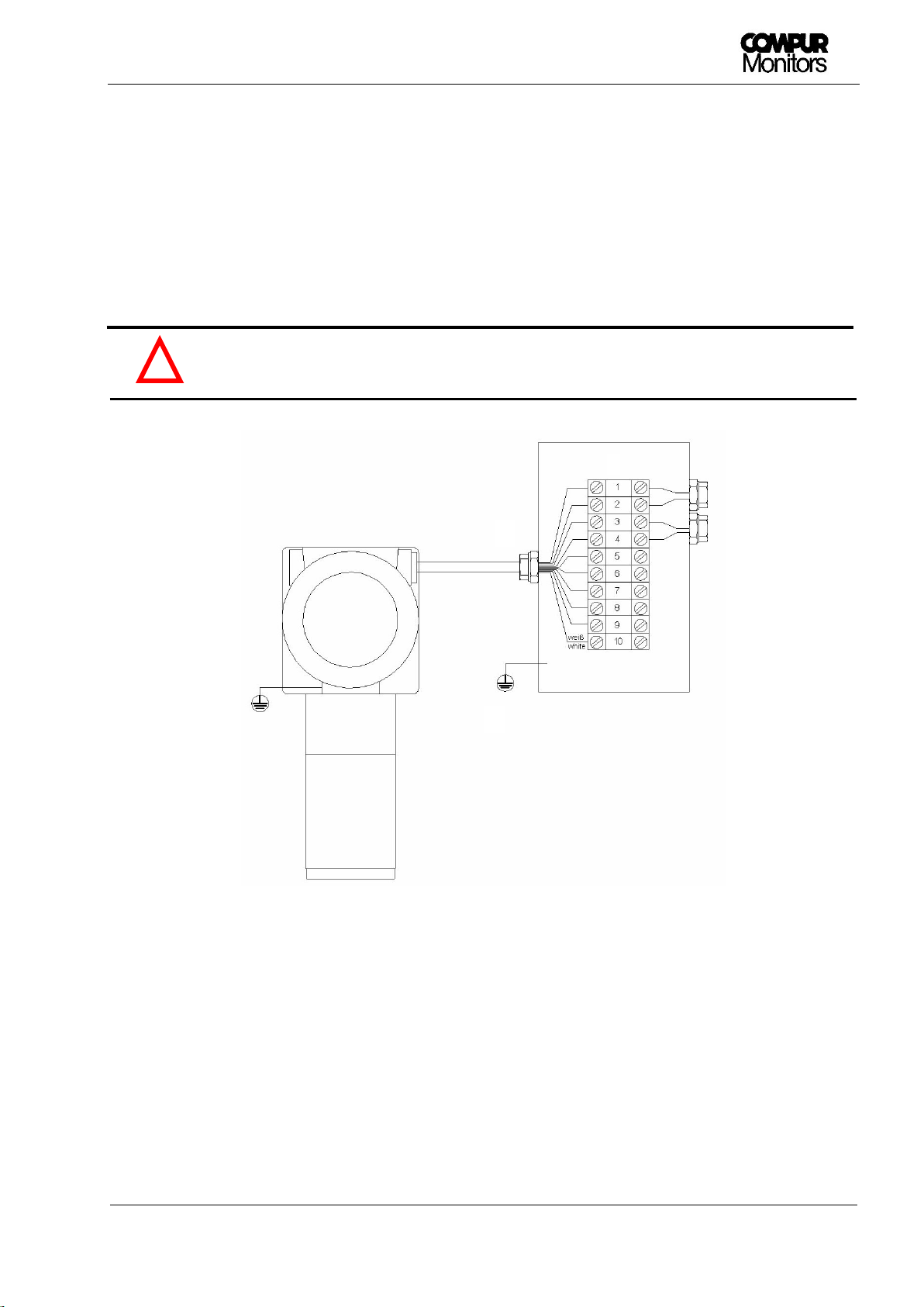
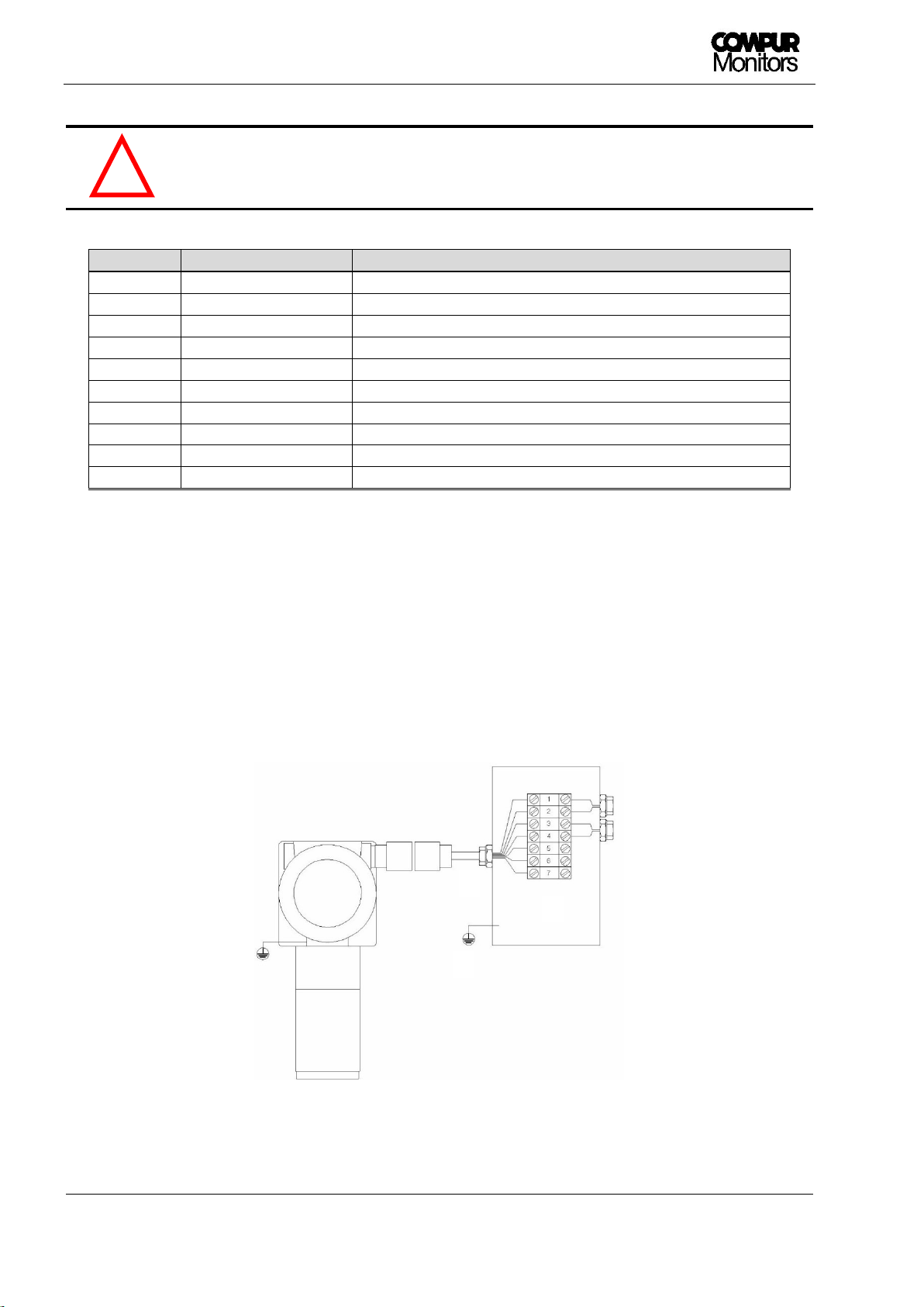
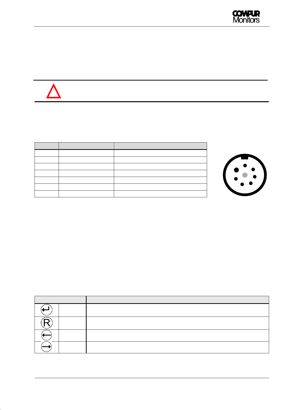
Connections: 10-core cable tail (1 m) or 7-pin eXLink plug
Open-Drain-outputs: 2 x alarm, 1 x system failure, 1 x maintenance request
Characteristic values max. 30 VDC / 2.5 A
SF-Open-Drain- output: In normal operation active (conductive)
Analog output: 0 mA in case of system failure
2 or 4 mA in the service mode, programmable
4 - 20 mA in the measuring mode
22 mA when full scale is exceeded
max. burden: 450 Ohm
EMC: EN 61000-6-4:2007 + A1:2011 / EN 50270:2015 (type 2)
Functional safety: SIL 2 compliant according to IEC 61508:2010
Automatic self-test: every 24 hours, time is selectable
Weight: ca. 4800 g
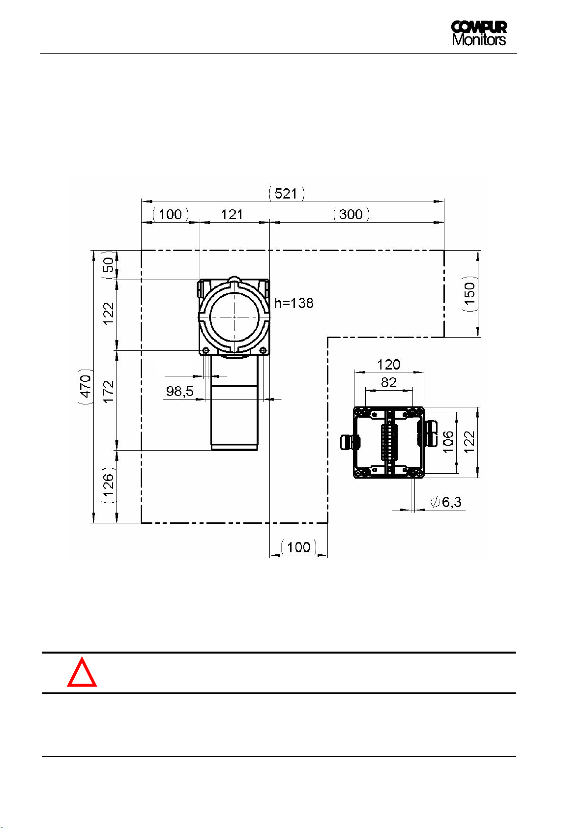
Dimensions: 121 x 294 x 138 mm (W x H x D)
Compur Monitors GmbH & Co. KG
Weißenseestraße 101
D-81539 München
Phone 0049 (0) 89 62038 268
Fax 0049 (0) 89 62038 184
Internet: www.compur.com
E-Mail: compur@compur.de
5377 000 997 07 01 562992
Specifications are subject to change without notice, and are provided only
for comparison of products. The conditions under which our products are
used, are beyond our control. Therefore, the user must fully test our
products and / or information to determine suitability for any intended use,
application, condition or situation. All information is given without warranty
or guarantee. Compur Monitors disclaims any liability, negligence or
otherwise, incurred in connection with the use of the products and
information. Any statement or recommendation not contained herein is
unauthorized and shall not bind Compur Monitors. Nothing herein shall be
construed as a recommendation to use any product in conflict with patents
covering any material or device or its use. No license is implied or in fact
granted under the claims of any patent. Instruments are manufactured by
Compur Monitors GmbH & Co. KG, Munich. The General Conditions of Supply
and Service of Compur Monitors GmbH & Co. KG, Munich, are applicable.
Other manuals for Statox 560
1
Table of contents
Other Compur Monitors Gas Detector manuals
Popular Gas Detector manuals by other brands

PNI
PNI SAFE HOUSE 200 user manual

Medem
Medem AGDS-2em v2 installation instructions

Crowcon
Crowcon Gas-Pro User & Operator Manual

Critical Environment Technologies
Critical Environment Technologies CGAS-AP installation manual

Tecnocontrol
Tecnocontrol SE137EO user manual

Tecnocontrol
Tecnocontrol TS220EO user manual