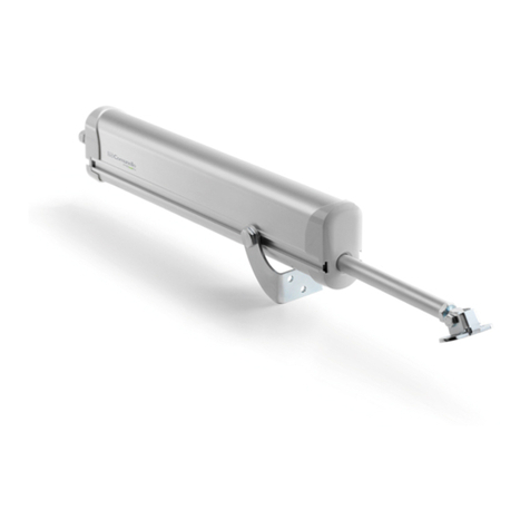
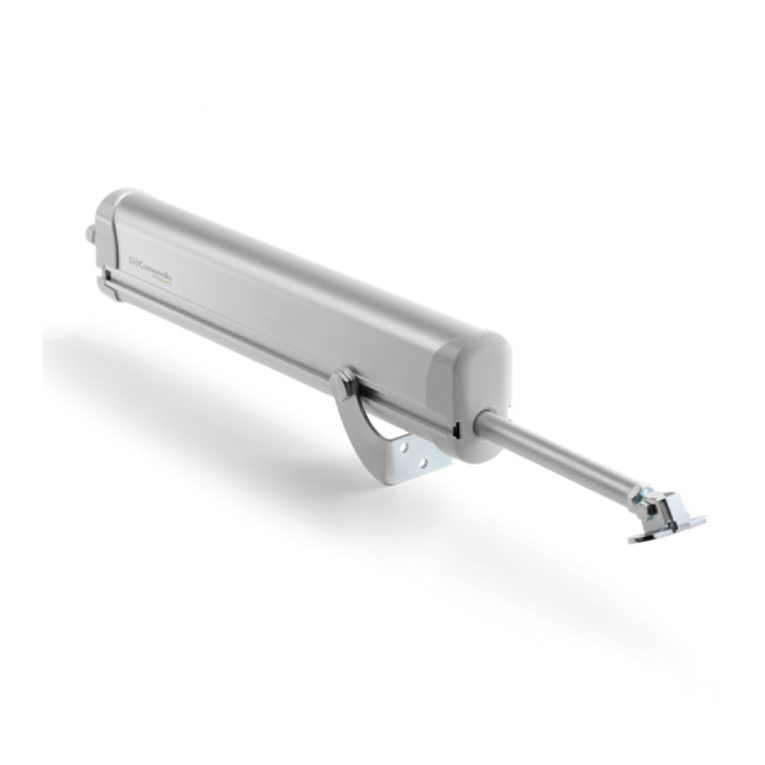
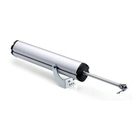
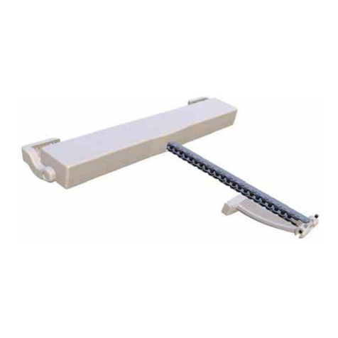
Comunello RAM 220 User manual

RAM 220 / 300 / 500
INSTALLATION AND USER’S MANUAL
Reversible electromechanical
actuator with telescopic rod
comunello.com
ISTRUZIONI D’USO E DI INSTALLAZIONE
INSTALLATIONS-UND GEBRAUCHSANLEITUNG
INSTRUCIONS D’UTILISATION ET D’INSTALLATION
INSTRUCCIONES DE USO Y DE INSTALACION
ИНСТРУКЦИЯ ПО МОНТАЖУ Rev. 00 - 10.12.13

2COMUNELLO ®Copyright 2013 - All right reserved
FIG. 1A
FIG. 2
FIG. 1B
RAM 220 / 300
MAX OPENING X Y Z K300 K500 W MAX
110 ° 150 152 77 925 1075 50
90 ° 170 182 77 885 1035 50
RAM 500
MAX OPENING X Y Z K300 K500 W MAX
110 ° 170 110 40 820 970 50
90 ° 170 110 40 880 1003 50
W
Y
X
90°
110° max
Z
K X
W
Y

3
COMUNELLO ®Copyright 2013 - All right reserved
FIG. 3
FIG. 4

4COMUNELLO ®Copyright 2013 - All right reserved
FIG. 7 FIG. 8
FIG. 9 FIG. 10
G
FIG. 5 FIG. 6

5
COMUNELLO ®Copyright 2013 - All right reserved
FIG. 12
FIG. 11
195
218
95
660 (RAM 220 / RAM 300)
809 (RAM 500)

6COMUNELLO ®Copyright 2013 - All right reserved
DICHIARAZIONE DEL FABBRICANTE
Fabbricante: Fratelli Comunello Spa
Indirizzo: Via Cassola 64, 36027 Rosà (VI) - Italia
Dichiara che l’automazione elettromeccanica per cancelli modello RAM:
• ècostruitaperessereincorporatainunamacchinaoperessereassemblataconaltrimacchinaripercostituireunamacchinaconsiderata
dalla Direttiva 98/37 CE;
• èconformeallecondizionidelleseguentialtreDirettiveCE:
Direttiva bassa tensione 2006/95 CE e successivi emendamenti secondo la normativa armonizzata EN 60335-1
Direttiva compatibilità elettromagnetica 2004/108/CE e successivi emendamenti secondo le normative EN 61000-6-2 e EN 61000-6-3
• èconformeallenormativeEN301489-1,EN301489-3,EN300220-2,EN622233,EN13241-1,EN12445,EN12453.
Inoltredichiarachenonèconsentitomettereinservizioilmacchinarionoachelamacchinaincuisaràincorporataodicuidiverrà
componentesiastataidenticataenesiastatadichiaratalaconformitàallecondizionidellaDirettiva98/37CEeallalegislazionenazionale
che la traspone.
Luca Comunello
Rappresentante legale della Fratelli Comunello
RAM 220 / 300 / 500
ISTRUZIONI D’USO E DI INSTALLAZIONE
Rappresentante legale della Fratelli Comunello
Fratelli Comunello S.p.A.
Azienda con Sistema Gestione Qualità certicato
UNI EN ISO 9001:2008.
(Certicaton°5010011235Rev.01)

7
COMUNELLO ®Copyright 2013 - All right reserved
ITALIANO
INDICE
1 AVVERTENZE GENERALI
1.1 Avvertenze per la sicurezza
1.2 Avvertenze per l’installazione
1.3 Avvertenze per l’uso
2 DESCRIZIONE DEL PRODOTTO E DESTINAZIONE D’USO
2.1 Descrizione
2.2 Installazione tipica
3 CARATTERISTICHE TECNICHE DEL PRODOTTO
4 INSTALLAZIONE
4.1 Verichepreliminari
4.2 Limiti d’impiego
4.3 Lavori di predisposizione all’installazione
4.4 Installazione del motoriduttore mod. RAM
4.4.1 Installazione
4.4.2 Installazionenecorsa
4.4.3 Sblocco manuale del motoriduttore
5 PREDISPOSIZIONE AI COLLEGAMENTI ELETTRICI
6 COLLAUDO
7 MANUTENZIONE DEL PRODOTTO
8 RICAMBI
9 SMALTIMENTO
1 AVVERTENZE
1.1 AVVERTENZE PER LA SICUREZZA
Il presente manuale di installazione è rivolto esclusivamente a personale
professionalmente competente. È necessario leggere tutte le istruzioni
primadiprocedereall’installazione.Tuttoquellochenonèespressamente
previstoinquesteistruzioninonèpermesso;usinonprevistipotrebbero
esserefonte di dannial prodotto emettere in pericolopersone e cose.
Il costruttore declina qualsiasi responsabilità dall’inosservanza della
buona tecnica nella costruzione dei cancelli, nonché delle deformazioni
che potrebbero vericarsi durante l’uso. Conservare questo manuale
anche per utilizzi futuri. La progettazione, la fabbricazione dei dispositivi
che compongono RAM ed il presente manuale rispettano pienamente la
normavigente.Considerandolesituazionidirischiochepossonovericarsi
durantel’installazioneel’usodiRAMènecessariocheanchel’installazione
avvenganelpienorispettodileggi,normeeregolamenti;inparticolare:
1.2 AVVERTENZE PER L’INSTALLAZIONE
• Primadiiniziarel’installazionevericarelanecessitàdiulterioridispositivi
e materiali che possono servire a completare l’automazione
conRAMinbaseallaspecicasituazioned’impiego.
• L’automatismo non deve essere utilizzato prima di aver effettuato la
messainserviziocomespecicatonelparagrafo.
• Ilmaterialedell’imballaggiodeveesseresmaltitonelpienorispettodella
normativa locale.
1.3 AVVERTENZE PER L’USO
• Non eseguire modiche su nessuna parte se non previste nel
presente manuale. Operazioni di questo tipo possono solo causare
malfunzionamento.Il costruttore declinaogni responsabilità perdanni
derivatidaprodottimodicati.
• Evitarechelepartidell’automatismopossanovenirimmerseinacquao
in altre sostanze liquide. Anche durante l’installazione evitare che liquidi
possano penetrare all’interno della centrale e di altri dispositivi aperti.
• Qualora sostanze liquide siano penetrate all’interno dei dispositivi
dell’automatismo, scollegare immediatamente l’alimentazione elettrica
e rivolgersi al servizio di assistenza; l’uso di RAM in tali situazioni può
causare situazioni di pericolo.
• Non tenere qualsiasi componente di RAM vicino a fonti di calore né
esporloaamme;taliazionipossonodanneggiarloedesserecausadi
malfunzionamenti,incendioosituazionidipericolo.
• Nel caso di lunghi periodi di inutilizzo, per evitare il rischio di perdite
disostanzenocivedallabatteriaopzionaleèpreferibileestrarlae
custodirla in luogo asciutto.
• Collegarelacentralesoloadunalineadialimentazioneelettricadotata
di messa a terra di sicurezza.
• Tutteleoperazionicherichiedonol’aperturadeiguscidiRAMdevono
avvenire con la centrale di comando scollegata dall’alimentazione
elettrica; se il dispositivo di sconnessione non è a vista apporvi un
cartello: “ATTENZIONE MANUTENZIONE IN CORSO”.
• Qualorasiverichinointerventidiinterruttoriautomaticiodifusibili,prima
diripristinarliènecessarioindividuareedeliminareilguasto.
• Nelcasodiguastononrisolvibilefacendousodelleinformazioniriportate
nelpresentemanuale,interpellareilserviziodiassistenza.
2 DESCRIZIONE DEL PRODOTTO
E DESTINAZIONE D’USO
2.1 DESCRIZIONE
Attuatore elettromeccanico telescopico ambidestro per cancelli residenziali.
La robusta struttura in alluminio pressofuso permette di alloggiare sia i
motoriaspazzolachemonofaserendendodisponibilesialaversione24
Vsialaversione230V.Lascoccainalluminioconverniciaturaapolvereè
resistenteagliagentiatmosferici.
RAM 220 RAM 300 RAM 500
Alimentazione motore 24 VDC 24 VDC 230 VAC 24 VDC 230 VAC
Potenza assorbita 70 W 110 W 280W 110 W 280 W
Assorbimento 3 A 5 A 1,2 A 5 A 1,2 A
Spinta Max 1500 N 2000 N 1800 N 1800 N 2000 N
Spinta Nominale 500 N 600 N 700 N 600 N 700 N
Intermittenza di lavoro 30% Intensivo 40% Intensivo 30%
Grado di protezione IP 24 D
Classe di isolamento 3 (selv) 3 (selv) 1 (a terra) 3 (selv) 1 (a terra)
Temp. di funzionamento da -20°C a + 50°C
Peso max del cancello VEDERE GRAFICO
Velocità 15mm/s 22 mm/s 15mm/s 22mm/s 15mm/s
Peso 7 Kg 7,8 Kg 8,3 Kg 8,8 Kg 9,3 Kg
3 CARATTERISTICHE TECNICHE DEL
PRODOTTO
E G
CC
F F
F
BB A A
D
2.2 INSTALLAZIONE TIPICA
LEGENDA
A MOTORIDUTTORE
B FOTOCELLULEINAPERTURA
C FOTOCELLULE IN CHIUSURA
D LAMPEGGIANTE
E SELETTORE A CHIAVE
F ARRESTO FINECORSA
G CENTRALINA ESTERNA

8COMUNELLO ®Copyright 2013 - All right reserved
4 INSTALLAZIONE
4.1 VERIFICHE PRELIMINARI
Prima di procedere all’installazione, è necessario vericare l’integrità dei
componenti del prodotto, l’adeguatezza del modello scelto e l’idoneità
dell’ambiente destinato all’installazione:
• Vericarechetuttoilmaterialedautilizzaresiainottimostatoeadatto
all’uso previsto.
• Vericarechelastrutturameccanicadelcancellosiaadattaadessere
automatizzata. Il presente prodotto non può automatizzare un cancello
chenonsiagiàefcienteesicuro;inoltre,nonpuòrisolveredifetticausati
da un’installazione errata del cancello o da una sua cattiva manutenzione.
• Vericare che le condizioni di funzionamento dei dispositivi siano
compatibili con i limiti d’impiego dichiarati.
• Muovere manualmente le ante del cancello nelle due direzioni e
accertarsichelosforzosiacostante.
• Portare manualmente le ante del cancello in una posizione qualsiasi;
quindilasciarlefermeeaccertarsichenonsimuovano.
• Vericarechelazonadissaggiodelmotoriduttoresiacompatibilecon
l’ingombrodiquest’ultimoedaccertarsichecisialospaziosufciente
per la rotazione completa del suo braccio.
• Nellevicinanzedelmotoriduttore,accertarsichecisiaspaziosufciente
pereffettuarelamanovramanualedisbloccodelmotoriduttore.
• Accertarsi che le superci scelte per installare i vari dispositivi, siano
solideepossanogarantireunssaggiostabile.
• Accertarsi che ciascun dispositivo da installare sia collocato in una
posizione protetta e al riparo da urti accidentali.
4.2 LIMITI D’IMPIEGO
Primadieseguirel’installazione,vericarecheilmotoresiacorrettamente
dimensionato al peso ed alla lunghezza delle ante e sia nei limiti dei valori
riportati nel capitolo 3 “Caratteristiche tecniche del prodotto”.
4.3 LAVORI DI PREDISPOSIZIONE ALL’INSTALLAZIONE
Facendo riferimento a FIG. 1A e a FIG. 1B, stabilire la posizione
approssimativa in cui verrà installato ciascun componente previsto
nell’impianto e lo schema di collegamento più appropriato. In seguito viene
riportata una lista dei componenti necessari:
• Motoriduttorielettromeccanici.
• Coppiadifotocellule.
• Coppiadibattentidiarrestoinaperturaebattentediarrestoinchiusura.
• Colonneperfotocellule.
• Segnalatorelampeggiante.
• Selettoreachiaveotastieradigitale.
• Elettroserraturaverticale(consigliataperchiusuresuperioria3m).
• Centraledicomando.
4.4 INSTALLAZIONE DEL MOTORIDUTTORE MOD. RAM
4.4.1 INSTALLAZIONE
• Effettuarelosbloccomanualecomedescrittonelcapitolo4.4.3.
• Stabilirelaposizionedell’automatismoincorrispondenzadiuntraversosolido.
• Fissare provvisoriamente la piastra posteriore al pilastro il
quale deve avere una larghezza minima di 100 mm (FIG. 2)
• Acancellocompletamentechiusossarelapiastraanterioreall’anta(FIG.3).
• Unireilmotoreallastaffaposterioremedianteviteedadoindotazione
(FIG.4).L’attuatorenonpuòessereinstallatoconilcoperchioversol’alto.
• Fissareilpistoneallapiastraanterioreutilizzandoviteedadoindotazione
(FIG.4).
4.4.2 INSTALLAZIONE FINECORSA
L’attuatore RAM non è provvisto di necorsa elettronici ed è quindi
indispensabile predisporre nel cancello da automatizzare degli arresti
meccanici in chiusura ed apertura.
4.4.3 SBLOCCO MANUALE DEL MOTORE
Lo sblocco manuale va attivato quando si deve aprire manualmente il
cancello. L’attivazione del sistema di sblocco potrebbe provocare movimenti
incontrollati del cancello nel caso in cui siano presenti sbilanciamenti o
guasti meccanici.
Persbloccareilmotoreproseguirecomesegue:
• Aprirelosportellinoinplasticaedinserirelamanigliadisblocco(FIG.5).
• Ruotarelamanigliainsensoorario(FIG.6).
• Inquestomodosirendefollel’ingranaggiopermettendocosì,l’apertura
manualedelcancello(FIG.7).
• Perripristinareilcomandomotorizzato,portarelamaniglianellaposizione
iniziale(Fig.8)
• Toglierelamanigliaeriporlainunluogosicuro(FIG.9).
5 PREDISPOSIZIONE AI COLLEGAMENTI
ELETTRICI
• Effetturelosbloccomanualecomeillustratonelparagrafo4.4.3.
• ToglierelaparteinplasticacomeillustratoinFIG.10.
• Allentarepressacavo“G”postonellaparteinferioredelmotore.FIG.10.
• Inserireilcavodell’alimentazioneFIG.11.
• Collegareiliallamorsettieracomeindicatonell’etichettavicino.
• Collegaremessaaterraalcapocordaadocchiellovicinoallamorsettiera
FIG. 11.
• Bloccareilcavoserrandoilpressacavo.
6 COLLAUDO
Ogni singolo elemento dell’automatismo, ad esempio bordi sensibili,
fotocellule, arresto di emergenza, ecc. richiede una specica fase di
collaudo; per questi dispositivi si dovranno eseguire le procedure riportate
neirispettivimanualid’istruzioni.PerilcollaudodiRAMeseguirelaseguente
sequenza di operazioni:
• Vericarechesiastatorispettatorigorosamentetuttoquantoprevistonel
presente manuale ed in particolare nel capitolo 1 “Avvertenze”.
• Utilizzando i dispositivi di comando o arresto previsti (selettore a
chiave,pulsantidicomandootrasmettitoriradio),effettuaredelleprove
di apertura, chiusura ed arresto del cancello e vericare che il
comportamento corrisponda a quanto previsto.
• Vericare uno ad uno il corretto funzionamento di tutti i dispositivi di
sicurezza presenti nell’impianto (fotocellule, bordi sensibili, arresto di
emergenza,ecc.).
• Se le situazioni pericolose provocate dal movimento dell’anta sono
state salvaguardate mediante la limitazione della forza d’impatto si
deve eseguire la misura della forza secondo quanto previsto dalla
norma EN 12445.
7 MANUTENZIONE DEL PRODOTTO
Lamanutenzionedeveessereeffettuataregolarmentedapartedipersonale
qualicatosecondoquantoprevistodalleleggienormativevigenti.PerRAM
ènecessariaunamanutenzioneprogrammataalmassimoentro6mesio
10.000 manovre dalla precedente manutenzione.
RAM 300RAM 220
PESO ANTA (Kg)
LUNGHEZZA ANTA (m)
LIMITI DI IMPIEGO - RAM 220 - RAM 300
PESO ANTA (Kg)
LUNGHEZZA ANTA (m)
LIMITI DI IMPIEGO - RAM 500

9
COMUNELLO ®Copyright 2013 - All right reserved
ITALIANO
• Scollegarequalsiasifontedialimentazionedalmotore.
• Vericareesotituiretuttelepartidimovimentousurate.
• Vericarelostatodideterioramentodituttelepartidell’automazione.
8 RICAMBI
Èpossibileacquistaredei particolari di ricambioincasodi tale necessità
contattare l’assistenza tecnica.
9 SMALTIMENTO
Alterminedellavitadell’automazione,assicuratevichelosmantellamentosia
eseguitodapersonalequalicatoecheimaterialivenganoriciclatiosmaltiti
secondo le norme valide a livello locale.

10 COMUNELLO ®Copyright 2013 - All right reserved
MANUFACTURER’S DECLARATION
Manufacturer: Fratelli Comunello Spa
Address: Via Cassola 64, 36027 Rosà (VI) - Italy
Declares that the RAM electromechanical gate opener:
• isdesignedtobeincorporatedinothermachineryorassembledwithothermachinerytoformacomplexinstallationasdescribedin
Directive 98/37 EC;
• isincompliancewiththeprovisionssetdownintheadditionalECDirectives:
“Lowvoltage”Directive2006/95ECasamendedinaccordancewithharmonizedstandardEN60335-1
“Electromagneticcompatibility”Directive2004/108/ECasamendedinaccordancewithstandardsEN61000-6-2andEN61000-6-3
isincompliancewithstandardsEN301489-1,EN301489-3,EN300220-2,EN622233,EN13241-1,EN12445,andEN12453
Andfurtherdeclaresthatitisprohibitedtocommissionthedeviceuntilthemachineryinwhichitwillbeincorporatedorofwhichitwill
becomeacomponenthasbeenidentiedanditsconformityhasbeendeclaredincompliancewiththeprovisionsofDirective98/37EC
andthenationallegislationthatimplementstheprovisionsoftheDirective.
Luca Comunello
Fratelli Comunello legal representative
RAM 220 / 300 / 500
INSTALLATION AND USER’S MANUAL
Luca Comunello
Fratelli Comunello legal representative
Fratelli Comunello S.p.A.
Company with certied Quality Management System
UNI EN ISO 9001:2008.
(Certicaten°5010011235Rev.01)

11
COMUNELLO ®Copyright 2013 - All right reserved
ENGLISH
CONTENTS
1 GENERAL PRESCRIPTIONS
1.1 Safetyprescriptions
1.2 Installation prescriptions
1.3 Operating prescriptions
2 MODELS AND PRODUCTS DESCRIPTION
2.1 Description
2.2 Typical installation
3 PRODUCT TECHNICAL SPECIFICATIONS
4 INSTALLATION
4.1 Preliminarychecks
4.2 Operating limits
4.3 Preparatoryworkforinstallation
4.4 Installing the RAM operator
4.4.1 Installation
4.4.2 Installationoflimitstopsandswitches
4.4.3 Operator manual release
5 PREPARATION FOR ELECTRICAL CONNECTIONS
6 TESTING
7 PRODUCT MAINTENANCE
8 SPARE PARTS
9 DISPOSAL OF THE PRODUCT
1 PRESCRIPTIONS
1.1 SAFETY PRESCRIPTIONS
This installation manual is addressed exclusively to professionally skilled
personnel.Readalltheinstructionscarefullybeforestartingtheinstallation
procedures. Any operations that are not expressly set down in these
instructions are to be considered prohibited; improper use may result in
damagetotheproductandplacepersonsandpropertyatrisk.
Themanufacturerdeclinesallliabilityforfailuretoobservebestpracticesin
gateconstructionandforanypossibledeformationthatmayoccurduring
useoftheproduct.Storethismanualinasafeplaceforfuturereference.
The design and construction of the devices of which model RAM is
composedandthismanualareinfullcompliancewithstatutorylegislation.
Inconsiderationofpotentialhazardsthatmayariseduringtheinstallation
and use of RAM, the installation procedures must be carried out in full
compliancewiththeapplicablelaws,standardsandregulations;namely:
1.2 INSTALLATION PRESCRIPTIONS
• Beforestartingtheinstallationproceduresmakesureyouhaveany
additional devices and materials that may be required to complete the
RAMgateopenerinconsiderationofthespecicapplication.
• Thegateopenermustnotbeuseduntilthesystemhasbeen
commissionedasspeciedinheading:
• Disposeofpackagingmaterialsincompliancewithlocalregulations.
1.3 OPERATING PRESCRIPTIONS
• No modications can be made to any part of the product unless
specied in this manual. Unauthorized modication of the product is
likelytoleadtomalfunctions.Themanufacturerdeclinesallliabilityfor
damagecausedbyunauthorizedmodications.
• Thepartsoftheautomationsystemmustneverbeimmersedinwater
or other liquids. During the installation procedures ensure that no liquids
penetrate inside the control unit or other open devices.
• Ifliquidspenetrateanypartsoftheautomationsystemdisconnectthe
electricalpower supplyimmediately andconsult Comunellotechnical
service;theuseofRAMinsuchconditionsmaygiverisetopotentially
hazardous situations.
• KeepallpartsoftheRAMgate opener away from heat sourcesand
openames;exposuretoheatoramesmaydamagethedevicesand
causefaults,re,orhazardoussituations.
• When the equipment remains unused for a long time, remove the
optionalbatteryandstoreitinadryplacetoavoidtheriskofleakageof
harmfulsubstances.
• Connectthecontrolunitexclusivelytoanelectricalpowersupplyline
equippedwithanefcientprotectiveearthconductor.
• Any operations that require the housing of RAM to be opened must
be performed with the control unit and the electrical power supply
disconnected;ifthedisconnectdeviceisnotclearlyvisiblefromwhere
you are working, attach a warning notice to the effect: “WARNING -
MAINTENANCEINPROGRESS”.
• Inthecaseoftrippingofcircuitbreakersorblowingoffuses,ndthe
faultandremedyitbeforeresettingthecircuitbreakerorchangingthe
fuse.
• Ifthefaultcannotberemediedusingtheinformationgiveninthismanual,
consult technical service.
2 PRODUCT DESCRIPTION AND INTENDED USE
2.1 PRODUCT DESCRIPTION
Reversible electromechanical operator with telescopic rod for residential
gates. The rugged die cast aluminium structure can accommodate brush
motorsorsinglephasemotors,sotheoperatorcanbesuppliedineithera
24Vversionora230Vversion.Aluminiumhousingwithweatherresistant
powdercoating.
RAM 220 RAM 300 RAM 500
Operator power supply 24 VDC 24 VDC 230 VAC 24 VDC 230 VAC
Power consumption 70 W 110 W 280W 110 W 280 W
Current input 3 A 5 A 1,2 A 5 A 1,2 A
Maximum thrust 1500 N 2000 N 1800 N 1800 N 2000 N
Nominal thrust 500 N 600 N 700 N 600 N 700 N
Duty cycle 30% Intensive 40% Intensive 30%
Protection rating IP 24 D
Insulation class 1 (earthing) 3 (selv) 3 (selv) 1
(earthing)
3 (selv) 1
(earthing)
Working temperature from from -20°C to + 50°C
Max weight of gate leaf SEE THE CHART
Speed 15mm/s 22 mm/s 15mm/s 22mm/s 15mm/s
Weight 7 Kg 7,8 Kg 8,3 Kg 8,8 Kg 9,3 Kg
3 PRODUCT TECHNICAL SPECIFICATIONS
E G
CC
F F
F
BB A A
D
2.2 TYPICAL INSTALLATION
KEY
A OPERATORWITHBUILT-INCONTROLUNIT
B OPENINGPHOTOCELLS
CCLOSINGPHOTOCELLS
D FLASHING LIGHT
E KEYSELECTORSWITCH
F LIMITSTOP
G EXTERNAL CONTROL UNIT

12 COMUNELLO ®Copyright 2013 - All right reserved
4 INSTALLATION
4.1 PRELIMINARY CHECKS
Before starting the installation work, check the condition of the product
components, the suitability of the chosen gate opener model and the
suitabilityoftheintendedinstallationenvironment:
• Ensurethatallmaterialusedisinperfectconditionandtforpurpose.
• Make sure that the mechanical structure of the gate is suitable for
automation. This product cannot be used to automate a gate unless
the gate is already in good working order and safe; furthermore, it
cannot remedy defects caused by incorrect installation or lack of
maintenanceofthegate.
• Checkthattheoperatingconditionsofthedevicesarecompatiblewith
the stated operating limits.
• Movethegateleavesmanuallyinbothdirectionstoensuretheforce
requiredisconstantthroughoutthefullrangeofmovement.
• Move the gate leaves manually to any position then release them to
checkthattheyremainstationary.
• Checkthattheareainwhichtheoperatoristobemountediscompatible
withthesizeoftheunitandmakesurethereissufcientclearancefor
thefullmovementofthearm.
• Ensurethatthereissufcientspacearoundtheoperatortoperformthe
manual release procedure.
• Ensurethatthesurfacesonwhichthedevicesaretobemountedare
solid and able to provide a secure anchorage.
• Ensurethatalldevicestobeinstalledareinaprotectedlocationsuch
thatminimizestheriskofaccidentalimpact.
4.2 OPERATING LIMITS
Beforestartingtheinstallationworkmakesuretheoperatoriscorrectlysized
inrelationtothedimensionsandlengthofthegateleavesandwithinthe
limitsofthevaluesgiveninthechapter“Producttechnicalspecications”.
4.3 PREPARATORY WORK FOR INSTALLATION
WithreferencetoFIG.1AeaFIG.1B,choosetheapproximateposition
inwhicheachcomponentofthesystemistobeinstalledandchoosethe
mostappropriateconnectionlayout.Listofcomponentsrequired:
• Electromechanicaloperators.
• Pairofphotocells.
• Pairofopeninglimitstopsandclosingstop.
• Postsforphotocells.
• Flashinglight.
• Keyselectorswitchordigitalkeypad.
• Verticalelectriclock(recommendedforgateleavesofmorethan3m).
• Controlunit.
4.4 INSTALLING THE RAM OPERATOR
4.4.1 INSTALLATION
Performthemanualreleaseasdescribedinheading4.4.3
• Choose the position for the gate opener in correspondence with a
sturdy cross member on the gate.
• Temporarilysecuretherearplatetothepillar,whichmustbeatleast100
mminwidth(FIG.2).
• Withthegatefullyclosed,xthefrontplatetothegateleaf(FIG.3).
• Coupletheoperatortotherearbracketusingthesuppliednutandbolt
(FIG.4).Theoperatorcannotbeinstalledwiththecoverupward.
• Fixtherodtothefrontplatewiththesuppliednutandbolt(FIG.4).
4.4.2INSTALLATIONOFLIMITSTOPSANDSWITCHES
TheRAMoperatorisnotequippedwithelectroniclimitswitchesanditis
thereforeessentialtoensurethatthegatetobeautomatedisequippedwith
mechanical opening and closing limit stops.
4.4.3OPERATORMANUALRELEASE
Perform the manual release procedure when the gate is to be opened
manually. Activation of the release system may result in uncontrolled
movementsofthegateinthepresenceofimbalanceormechanicalfaults.
Toreleasetheoperator,proceedasfollows:
• Opentheplastichatchandinsertthereleasehandle(FIG.5).
• Turnthehandleclockwise(FIG.6).
• Thisactionservestodisengagethegeartherebyallowingthegatetobe
openedmanually(FIG.7).
• To resume automatic control of the gate, return the key to its initial
position(FIG.8)
• Removethereleasehandleandstowitinasafeplace(FIG.9).
5 PREPARATION FOR ELECTRICAL
CONNECTIONS
• Performthemanualreleaseasillustratedinheading4.4.3.
• RemovetheplasticcoverasshowninFIG.10.
• Loosencablegland“G”locatedonthelowersideoftheoperatorFIG.10.
• InsertthepowercableFIG.11.
• Connectthewirestotheterminalboardasshownontheadjacentlabel.
• Connecttheearthwiretotheterminaleyenexttotheterminalboard
FIG. 11.
• Securethecablebytighteningthecablegland.
6 TESTING
Each part of the automation system, e.g. safety edges, photocells,
emergency stop, etc. must be tested; follow the procedures shown in
theinstructionmanualssuppliedwiththedevicesinquestion.Performthe
followingsequenceofoperationsfortestingofRAM:
• Checkthatalltheprescriptionsinthismanualhavebeenfollowedscrupulously,
withspecialattentiontothematterssetdowninchapter1“Prescriptions”.
• Using the supplied control or stopping devices (key selector switch,
controlbuttonsorradiotrasmitters),performgateopening,closingand
stoppingtestsandmakesurethegaterespondscorrectlytothevarious
commands.
• Checkoperationofallthesystem’ssafetydevices(photocells,safety
edges,emergencystop,etc.)onebyone.
• Ifpotentiallyhazardoussituationscausedbymovementofthegateleaf
havebeeneliminatedbylimitationofimpactforce,theassociatedforce
must be measured as prescribed in standard EN 12445.
7 PRODUCT MAINTENANCE
Maintenancemustbecarriedoutatregularintervalsbyqualiedpersonnel
incompliancewiththeprovisionsofstatutorylegislationandtheregulations
in force. RAM must be serviced at least once every 6 months or after
10.000 operating cycles since the last service.
• Disconnecttheoperatorfromallpowersupplies
• Checkallthemovingpartsandreplaceanywornparts.
• Checkallpartsoftheautomationsystemforsignsofdeterioration.
RAM 300RAM 220
LEAF WEIGHT (Kg)
LEAF LENGHT (m)
LIMITS OF USE - RAM 220 - RAM 300
LEAF WEIGHT (Kg)
LEAF LENGHT (m)
LIMITS OF USE - RAM 500

13
COMUNELLO ®Copyright 2013 - All right reserved
ENGLISH
8 SPARE PARTS
Spare parts can be purchased by contacting technical service.
9 DISPOSAL
Attheendofitsusefullifetheautomationsystemmustbedismantledby
qualiedpersonnelandthematerialsmustbe recycled or disposed of in
compliancewiththelocallegislationinforce.

14 COMUNELLO ®Copyright 2013 - All right reserved
ERKLÄRUNG DES HERSTELLERS
Der Hersteller Fratelli Comunello Spa
Anschrift: Via Cassola 64, 36027 Rosà (VI) - Italien
Erklärt,dassderelektromechanischeautomatischeTorantriebModellRAM:
• fürdenEinbauineineMaschinegebautist,oderfürdenZusammenbaumitanderenMaschinen,umeineMaschinegemäßRichtlinie
98/37 EG zu gestalten;
• denBedingungenderfolgendenzusätzlichenEG-Richtlinienentspricht:
Niederspannungsrichtlinie 2006/95 EG und Folgerichtlinien nach der harmonisierten Norm EN 60335-1
Richtlinie2004/108/EGüberdieelektromagnetischeVerträglichkeitundFolgerichtliniennachdenNormenEN61000-6-2undEN61000-6-3
• denNormenEN301489-1,EN301489-3,EN300220-2,EN622233,EN13241-1,EN12445,EN12453entspricht.
Underklärtaußerdem,dassesnichterlaubtist,dieVorrichtunginBetriebzusetzen,solangedieMaschine,indiesieeingebautwird
odermitdersiezusammengebautwird,identiziertwurdeundderenKonformitätmitdenBedingungenderRichtlinie98/37/EGundden
entsprechendennationalenGesetzgebungenerklärtwurde.
Luca Comunello
Rechtsvertreter der Firma Fratelli Comunello
RAM 220 / 300 / 500
BEDIENUNGSANLEITUNG
Rechtsvertreter der Firma Fratelli Comunello
Fratelli Comunello S.p.A.
Unternehmen mit UNI EN ISO 9001:2008
zertizierten Qualitätssystem
(Bescheinigungn°5010011235Rev.01)

15
COMUNELLO ®Copyright 2013 - All right reserved
DEUTSCH
INHALTSVERZEICHNIS
1 ALLGEMEINE HINWEISE
1.1 Sicherheitshinweise
1.2 Installationshinweise
1.3 Gebrauchshinweise
2 MODELLE UND PRODUKTBESCHREIBUNGEN
2.1 Beschreibung
2.2 Typische Installation
3 TECHNISCHE EIGENSCHAFTEN DES PRODUKTS
4 INSTALLATION
4.1 VorbereitendeÜberprüfungen
4.2 Einsatzgrenzen
4.3 Vorbereitungen vor der Installation
4.4 Installation des Getriebemotors Mod. RAM
4.4.1 Installation
4.4.2 InstallationderEndanschläge
4.4.3 Manuelles Entriegeln des Getriebemotors
5 VORBEREITUNG AUF DIE ELEKTRISCHEN ANSCHLÜSSE
6 PRÜFUNG
7 INSTANDHALTUNG DES PRODUKTS
8 ERSATZTEILE
9 ENTSORGUNG DES PRODUKTS
1 HINWEISE
1.1 SICHERHEITSHINWEISE
DiesesInstallationshandbuch wendet sichausschließlichanprofessionell
kompetentes Personal. Alle Anleitungen sind vor der Installation
durchzulesen. Alle nicht ausdrücklich in dieser Anleitung enthaltenen
Vorgänge sind nicht erlaubt; nicht bestimmungsgemäße Verwendungen
könnten Produktschäden verursachen und Personen und Gegenstände
inGefahrversetzen.DerHerstellerübernimmtkeineVerantwortungfürdie
NichteinhaltungderRegelnderTechnikbeiderFertigungderTore,sowie
für Verformungen, die sich beim Gebrauch ereignen könnten. Dieses
Handbuch ist auch für zukünftige Benutzungen aufzubewahren. Das
Projekt,dieFertigungderzuRAMgehörendenVorrichtungenunddieses
HandbucherfülleninvollemAusmaßdiegeltendenVorschriften.
Unter Berücksichtigung der Risikosituationen, die sich während der
InstallationunddemGebrauchvonRAMereignenkönnen,mussauchdie
Installation unter voller Einhaltung der Gesetze, Vorschriften und Regeln
erfolgen;insbesondere:
1.2 INSTALLATIONSHINWEISE
• Vor Beginn der Installation prüfen, ob zusätzliche Vorrichtungen und
Materialiennotwendigsind,diejenachderspezifischenVerwendungzur
KomplettierungderAutomatisierungmitRAMdienenkönnen.
• Das Antriebssystem darf nicht verwendet werden, solange die
InbetriebnahmenichtwieimentsprechendenAbsatzangeführterfolgtist.
• Das Verpackungsmaterial ist unter voller Einhaltung der örtlichen
Vorschriftenzuentsorgen.
1.3 GEBRAUCHSHINWEISE
• Es dürfen nirgendwo Änderungen durchgeführt werden, sofern nicht
in diesem Handbuch vorgesehen. Arbeiten dieser Art können lediglich
Betriebsstörungen verursachen. Der Hersteller übernimmt keine
VerantwortungfürSchäden,dievonverändertenProduktenherführen.
• Es ist zu vermeiden, dass Teile des Antriebssystems in Wasser oder
andereüssigeStoffetauchenkönnen.AuchwährendderInstallationist
zuvermeiden,dassFlüssigkeitenindieSteuerungundandereoffenen
Vorrichtungeneindringenkönnen.
• FallsüssigeStoffeindieVorrichtungenderAutomatikeingedrungensind,
istunverzüglichdieStromversorgungabzutrennenundderKundendienst
zuRatezuziehen;eineVerwendungvonRAMindiesemZustandkann
Gefahrsituationenverursachen.
• Die Bestandteile von RAM dürfen keinen Hitzequellen oder Flammen
ausgesetzt werden; sie könnten dadurch beschädigt werden und
Betriebsstörungen,BrändeoderGefahrsituationenverursachen.
• BeilängeremStillstandsolltedereventuelleAkkuentferntundaneinem
trockenen Ort aufbewahrt werden, um das Risiko des Austretens
schädlicherStoffezuvermeiden.
• Die Steuerung darf nur an eine Stromleitung mit Schutzerdung
angeschlossenwerden.
• Vor allen Vorgängen, die eine Öffnung der RAM-Gehäuse verlangen,
mussdieSteuerungerstvonderStromversorgungabgetrenntwerden;
fallsdieAbschaltvorrichtungnichtsichtbarist,isteinSchildanzubringen:
„ACHTUNG!IMWARTUNGSZUSTAND”.
• Falls Selbstabschalter oder Sicherungen ansprechen, ist vor ihrer
Rückstellung bzw. Instandsetzung der Defekt zu erkennen und zu
beseitigen.
• Im Falle von Defekten, die mit den in diesem Handbuch enthaltenen
Information nicht behoben werden können, ist mit dem Kundendienst
Kontaktaufzunehmen.
2 PRODUKTBESCHREIBUNG UND
BESTIMMUNGSZWECK
2.1 PRODUKTBESCHREIBUNG
Elektromechanischer Teleskopantrieb in beidseitiger Version für
Wohnhaustore.DierobusteStrukturausAludruckgussnimmtsowohldie
Bürstenmotoren wie auch die Einphasenmotoren auf, deshalb sind die
beidenAusführungenmit24Vund230Vverfügbar.
DasmitPulverlacklackierteAlugehäuseistwitterungsfest.
RAM 220 RAM 300 RAM 500
Motorspeisung 24 VDC 24 VDC 230 VAC 24 VDC 230 VAC
Leistungsaufnahme 70 W 110 W 280 W 110 W 280 W
Aufnahme 3 A 5 A 1,2 A 5 A 1,2 A
Max. Schubkraft 1500 N 2000 N 1800 N 1800 N 2000 N
Nennschubkraft 500 N 600 N 700 N 600 N 700 N
Einschaltdauer 30% Intensiv 40% Intensiv 30%
Schutzgrad IP 24 D
Isolationsklasse 3 (selv) 3 (selv) 1
(Erdung)
3 (selv) 1
(Erdung)
Betriebstemperatur von -20°C bis + 50°C
Max. Torgewicht BITTE TABELLE ANSCHAUEN
Laufzeit 15mm/s 22 mm/s 15mm/s 22mm/s 15mm/s
Gewicht 7 Kg 7,8 Kg 8,3 Kg 8,8 Kg 9,3 Kg
3 TECHNISCHE EIGENSCHAFTEN DES
PRODUKTS
E G
CC
F F
F
BB A A
D
2.2 TYPISCHE INSTALLATION
LEGENDE
A GETRIEBEMOTOR MIT INTEGRIERTER STEUERUNG
B FOTOZELLENÖFFNUNG
C FOTOZELLEN SCHLIESSUNG
D BLINKLEUCHTE
E BLINKLEUCHTE
F ENDANSCHLAG
G EXTERNE STEUERUNG

16 COMUNELLO ®Copyright 2013 - All right reserved
4 INSTALLATION
4.1 VORBEREITENDE ÜBERPRÜFUNGEN
Vor der Installation ist zu prüfen, dass die Bestandteile des Produktes
einwandfrei sind, das gewählte Modell angemessen und der
Installationsbereich geeignet sind:
• Prüfen, dass das zu verwendende Material insgesamt einen
ausgezeichnetenZustandaufweistundfürdenbestimmungsgemäßen
Gebrauch geeignet ist.
• Prüfen,dassdiemechanischeStrukturdesToresfürdieAutomatisierung
geeignet ist. Dieses Produkt kann kein Tor automatisieren, das nicht
allein schon efzient und sicher ist; außerdem kann es keine Fehler
beheben, die von einer falschen Installation des Tores oder seiner
schlechtenWartungverursachtsind.
• Prüfen, dass die Betriebsbedingungen der Vorrichtungen mit den
bescheinigtenEinsatzgrenzenverträglichsind.
• Den Torügel von Hand in beide Richtungen bewegen, um sich der
konstantenSchubkraftzuvergewissern.
• DieTorügelvonHandinegalwelchePositionbringen,stehenlassen
undfeststellen,dasssiesichnichtbewegen.
• Prüfen,dassderBefestigungsbereichdesGetriebemotorsmitseinen
äußeren Abmessungen verträglich ist und sicherstellen, dass ein
ausreichenderPlatzfürseinekompletteArmdrehungvorhandenist.
• InderNähedesGetriebemotorssicherstellen,dassfürdiemanuellen
Entriegelungsmanöver des Getriebemotors ein ausreichender Platz
vorhanden ist.
• Sicherstellen, dass die für die Installation der verschiedenen
Vorrichtungen gewählten Oberächen tragfähig sind und eine stabile
Befestigunggarantieren.
• Sicherstellen, dass sich jede zu installierende Vorrichtung an einer
geschütztenundvorunerwünschtenStößensicherenPositionbendet.
4.2 EINSATZGRENZEN
Vor der Installation prüfen, dass der Motor für das Gewicht und die
LängederFlügelbemessenistundinnerhalbderGrenzwertelautKapitel
„TechnischeEigenschaftendesProdukts“liegt.
4.3 VORBEREITUNGEN VOR DER INSTALLATION
UnterBezugnahmeaufdieABB.1AundABB.1BdieungefährePosition
bestimmen,anderjederBestandteilderAnlageinstalliertwird,sowieden
idealenSchaltplan.EsfolgteineAufstellungdernotwendigenBestandteile:
• ElektromechanischeGetriebemotoren.
• PaarFotozellen.
• Paar Feststellanschläge für die Öffnung und Feststellanschlag für die
Schließung.
• StandsäulenfürFotozellen.
• Blinkanzeiger.
• SchlüsseltasteroderdigitaleTastatur.
• VertikalesElektroschloss(empfohlenfürToreüber3m).
• Steuerung.
4.4 INSTALLATION DES GETRIEBEMOTORS RAM
4.4.1 INSTALLATION
• DiemanuelleEntriegelungwieimKap.4.4.3beschriebenvornehmen.
• DiePositiondesAntriebssystemsaneinemfestenQuerträgerbestimmen.
• DiehinterePlatteamPfeilereinstweiligbefestigen,dermindestens100
mmbreitseinmuss(ABB.2).
• BeikomplettgeschlossenemTordievorderePlatteamFlügel
befestigen(ABB.3).
• MitderbeigestelltenSchraubeundMutterdenMotormitdemhinteren
Bügelverbinden(ABB.4).
• DerAntriebkannnichtmitnachobenzeigendemDeckelinstalliertwerden.
• MitderbeigestelltenSchraubeundMutterdenKolbenandervorderen
Plattebefestigen(ABB.4).
4.4.2INSTALLATIONDERENDANSCHLÄGE
Der Antrieb RAM ist nicht mit elektronischen Endschaltern ausgestattet;
deshalb ist es unbedingt erforderlich, an dem zu automatisierenden Tor
mechanischeSchließ-undÖffnungsanschlägeeinzusetzen.
4.4.3 MANUELLES ENTRIEGELN DES MOTORS
Die manuelle Entriegelung ist durchzuführen, wenn das Tor manuell
geöffnet werden muss. Die Aktivierung des Entriegelungssystems
könnte unkontrollierte Torbewegungen bewirken, wenn Unwuchten oder
mechanischeDefektevorliegen.
ZurEntriegelungdesMotorsfolgendeSchritteausführen:
• DieKunststoffklappeöffnenunddenEntriegelungsgriffeinstecken(ABB.5).
• DenGriffimUhrzeigersinndrehen(ABB.6).
• IndieserWeisewirdderFreilaufdesZahnradesgeschaltetunddiemanuelle
Toröffnungermöglicht(ABB.7).
• Zur Rückstellung der Motorsteuerung, den Griff in die Ausgangsposition
rücken(ABB.8).
• DenGriffentfernenundaneinemsicherenOrtablegen.(ABB.9).
5 VORBEREITUNG AUF DIE ELEKTRISCHEN
ANSCHLÜSSE
• DiemanuelleEntriegelungwieimABS.4.4.3dargestelltausführen.
• DenKunststoffteilwieinderABB.10dargestelltentfernen.
• DieKabelklemme“G”amunterenMotorbereichlockern.ABB.10.
• DasSpeisekabeleinführenABB.11.
• DieKabelanderKlemmenleisteanschließen,gemäßAngabeaufdem
Etikettnebenan.
• DieErdungamRingkabelschuhnebenderKlemmenleisteanschließen
ABB. 11.
• DasKabeldurchFestziehenderKabelklemmeblockieren.
6 PRÜFUNG
JedeseinzelneElementdesAntriebssystems,z.B.dieSicherheitsleisten,
Fotozellen, Notabschalter, usw., verlangt eine spezische Prüfphase; an
allendiesenVorrichtungensinddieindenjeweiligenAnleitungshandbüchern
enthaltenenProzedurendurchzuführen.BeiderPrüfungvonRAMsinddie
folgendenArbeitsschritteerforderlich:
• Prüfen, dass alle in diesem Handbuch und besonders im Kapitel „1
Hinweise“enthaltenenVorgabenstrikteingehaltenwurden.
• Unter Verwendung der Bedienungs- oder Ausschaltvorrichtungen
(Schlüsseltaster, Bedienungstaster oder Funksender), AUF-STOP-ZU
VersuchemitdemTordurchführenunddasvorschriftsmäßigeVerhalten
prüfen.
• AlleSicherheitsvorrichtungenderAnlage(Fotozellen,Sicherheitsleisten,
Notabschalter, usw.) einzeln nach ihrer korrekten Betriebsfähigkeit
überprüfen.
• FallsdievonderFlügelbewegungverursachtenGefahrsituationendurch
dieSelbsthemmungderPrallkraftgewahrtwurden,isteineKraftmessung
nachEN12445durchzuführen.
RAM 300RAM 220
FLÜGELGEWICHT (Kg)
FLÜGELLÄNGE (m)
MAXIMALE ANWENDUNGEN - RAM 220 - RAM 300
FLÜGELGEWICHT (Kg)
FLÜGELLÄNGE (m)
MAXIMALE ANWENDUNGEN - RAM 500

17
COMUNELLO ®Copyright 2013 - All right reserved
DEUTSCH
7 INSTANDHALTUNG DES PRODUKTS
Qualiziertes Personal muss regelmäßig die Instandhaltung nach den
geltenden Gesetzen und Normvorschriften durchführen. RAM verlangt
eineprogrammierteInstandhaltungnachmaximal6Monatenoder10.000
ManövernabderletztenWartung.
• AlleVersorgungsquellenvomMotorabtrennen.
• AlleBewegungselementeüberprüfenundabgenutzteTeileauswechseln.
• AlleBestandteiledesAntriebssystemsaufihrenAbnutzungszustand
überprüfen.
8 ERSATZTEILE
Es besteht die Möglichkeit, Ersatzteile zu erwerben; notfalls ist hierzu mit
demtechnischenKundendienstKontaktaufzunehmen.
9 ENTSORGUNG
NachLebensendedesAntriebssystemssicherstellen,dassdieAbrüstung
vonqualiziertemPersonaldurchgeführtwirdunddieMaterialiennachörtlich
geltendenVorschriftenrezykliertoderentsorgtwerden.

18 COMUNELLO ®Copyright 2013 - All right reserved
DÉCLARATION DU FABRICANT
Fabricant: Fratelli Comunello Spa
Adresse: Via Cassola 64, 36027 Rosà (VI) - Italie
Nousdéclaronsquel’automatismeélectromécaniquepourportailsmodèleRAM:
• aétéconstruitpourêtreintégréàunemachineoupourêtremontésurd’autresmachinesafindeconstituerunemachineprévuepar
la Directive 98/37 CE;
• estconformeauxexigencesdesautresdirectivesCEsuivantes:
Directivebassetension2006/95CEetmodificationssuccessivesselonlanormeharmoniséeEN60335-1
Directivecompatibilitéélectromagnétique2004/108/CEetmodificationssuccessivesselonlesnormesEN61000-6-2etEN61000-6-3
• estconformeauxnormesEN301489-1,EN301489-3,EN300220-2,EN622233,EN13241-1,EN12445,EN12453
Nous déclarons en outre que la machine ne pourra pas être mise en service avant identication et déclaration de conformité aux
conditionsdelaDirective98/37CEetàlalégislationnationalelatransposantdelamachineàlaquelleelleseraintégréeoudontelle
deviendrapartieintégrante.
Luca Comunello
ReprésentantlégaldelasociétéFratelliComunello
RAM 220 / 300 / 500
MODE D’EMPLOI
ReprésentantlégaldelasociétéFratelliComunello
Fratelli Comunello S.p.A.
Enterprise avec Système de Management de la Qualité certié
UNI EN ISO 9001:2008
(Certicatn°5010011235Rev.01)

19
COMUNELLO ®Copyright 2013 - All right reserved
FRANÇAIS
SOMMAIRE
1 AVERTISSEMENTS GÉNÉRAUX
1.1 Avertissementsconcernantlasécurité
1.2 Avertissements concernant l’installation
1.3 Avertissements concernant l’utilisation
2 MODÈLES ET DESCRIPTION PRODUITS
2.1 Description
2.2 Installation type
3 CARACTÉRISTIQUES TECHNIQUES DU PRODUIT
4 INSTALLATION
4.1 Contrôlespréliminaires
4.2 Limites d’utilisation
4.3 Travauxpréalablesàl’installation
4.4 Installationdel’opérateurmod.RAM
4.4.1 Installation
4.4.2 Installationndecourse
4.4.3 Débrayagemanueldel’opérateur
5 PRÉDISPOSITION AUX BRANCHEMENTS ÉLECTRIQUES
6 ESSAI
7 ENTRETIEN
8 PIÈCES DÉTACHÉES
9 ÉLIMINATION
1 AVERTISSEMENTS
1.1 AVERTISSEMENTS CONCERNANT LA SÉCURITÉ
Cemanueld’installations’adresseexclusivementàunpersonnelcompétent.
Ilestindispensabled’avoirlutouteslesinstructionsavantdeprocéderà
l’installation,Toutes les opérations nonexpressément prévuesdans ces
instructionssontinterdites;touteutilisationnonprévuepeutentraînerdes
dommagesmatérielsetdesrisquesdeblessures.Leconstructeurdécline
toute responsabilité en cas de non-observation des règles de bonne
technique dans la construction des portails ou en cas de déformations
survenant durant l’utilisation. Conserver ce manuel pour toute future
consultation. La conception et la fabrication des dispositifs composant
RAMetcemanuelsontrigoureusementconformesauxnormesenvigueur.
Étant donné les situations de risques pouvant se présenter durant
l’installation et l’utilisation de RAM, l’installation doit nécessairement être
effectuéeenstricteconformitéavecleslois,normesetréglementations;
en particulier:
1.2 AVERTISSEMENTS CONCERNANT L’INSTALLATION
• Avantdeprocéderàl’installation,vérifierlanécessitééventuelled’autres
dispositifsetmatérielspermettantdecompléterl’automatismeRAMen
fonctiondel’utilisationprévue.
• L’automatismenepeutpasêtreutilisétantquelamiseenservicen’a
pasétéeffectuéecommespécifiéauchapitre.
• Éliminerlematérield’emballageconformémentauxnormeslocales.
1.3 AVERTISSEMENTS CONCERNANT L’UTILISATION
• N’effectueraucunemodication sur quelque composantquece soit,
sauf prévue dans ce manuel. Ce type d’intervention est uniquement
susceptibled’entraînerdesdysfonctionnements.
Le constructeur décline toute responsabilité en cas de dommages
entraînésparunemodicationduproduit.
• Éviter toute immersion de composants de l’automatisme dans l’eau
ou dans d’autres liquides. Durant l’installation, éviter également toute
pénétrationdeliquidesàl’intérieurducoffretdecommandeetd’autres
dispositifsouverts.
• En cas de pénétration d’un liquide à l’intérieur des dispositifs de
l’automatisme, sectionner immédiatement l’alimentation électrique et
s’adresser au service d’assistance; toute utilisation de RAM dans une
telle situation comporte des risques.
• NepaslaisserlescomposantsdeRAMàproximitédesourcesdechaleur
etnepaslesexposeràdesammessouspeined’endommagementet
dedysfonctionnement,incendieousituationdedanger.
• Encasd’inutilisationprolongée,envued’évitertoutrisquedepertesde
substancesnocivesdelabatterieenoption,ilestconseilléderetirer
cettedernièreetdelaconserverdansunendroitsec.
• Brancheruniquementlecoffretàuneligned’alimentationéquipéed’une
miseàlaterredesécurité.
• Touteslesopérationsexigeantl’ouvertureducarterdeRAMdoiventêtre
effectuéesaveclecoffretdecommandedébranchéedel’alimentation
électrique;siledispositifdedéconnexionenestdépourvu,prévoirun
panneau: «ATTENTION ENTRETIEN EN COURS».
• En cas d’intervention d’interrupteurs automatiques ou de fusibles,
identieretéliminerleproblèmeavantdelesréarmer.
• Encasdepannenepouvantêtrerésolueaumoyendesinformations
fourniesdanscemanuel,contacterleserviced’assistance.
2 DESCRIPTION DU PRODUIT ET APPLICATION
2.1 DESCRIPTION DU PRODUIT
Opérateur électromécanique télescopique ambidextre pour portails
résidentiels.Sasolidestructureenaluminiummoulésouspressionpermet
delogerlesmoteursàbalaisoumonophasésenversionà24Vou230V.
Le carter en aluminium revêtu poudre est résistant aux agents
atmosphériques.
RAM 220 RAM 300 RAM 500
Alimentation moteur 24 VDC 24 VDC 230 VAC 24 VDC 230 VAC
Puissance absorbée 70 W 110 W 280W 110 W 280W
Absorption 3 A 5 A 1,2 A 5 A 1,2 A
Poussée max. 1500 N 2000 N 1800 N 1800 N 2000 N
Poussée nominale 500 N 600 N 700 N 600 N 700 N
Fonctionnement
intermittent
30% Intensif 40% Intensif 30%
Indice de protection IP 24 D
Classe d’isolation 3 (selv) 3 (selv) 1 (Mise à
la terre)
3 (selv) 1 (Mise à
la terre)
Temp. de fonctionnement de -20°C à + 50°C
Poids max. du portail VOIR LE GRAPHE
Vitesse 15mm/s 22 mm/s 15mm/s 22mm/s 15mm/s
Poids 7 Kg 7,8 Kg 8,3 Kg 8,8 Kg 9,3 Kg
3 CARACTÉRISTIQUES TECHNIQUES DU
PRODUIT
E G
CC
F F
F
BB A A
D
2.2 INSTALLATION TYPE
LÉGENDE
A OPÉRATEURÀLOGIQUEDECOMMANDEINTERNE
B PHOTOCELLULESENOUVERTURE
CPHOTOCELLULEENFERMETURE
D CLIGNOTANT
E SÉLECTEURÀCLÉ
F ARRÊT FIN DE COURSE
G CENTRALE EXTERNE

20 COMUNELLO ®Copyright 2013 - All right reserved
4 INSTALLATION
4.1 CONTRÔLES PRÉLIMINAIRES
Avantdeprocéderàl’installation,vérierquelescomposantsduproduitsont
enbonétatetquelemodèlechoisiestadaptéaulieud’installationprévu:
• Vérier que tout le matériel à utiliser est en parfait état et adapté à
l’utilisationprévue.
• Vérier que la structure mécanique du portail est prévue pour être
équipée d’un automatisme. Ce produit peut uniquement équiper un
portailenparfaitétat-entermesdefonctionnementetdesécurité;ilne
pourraenoutrerésoudrelesproblèmesliésàuneinstallationincorrecte
ouàunentretieninsufsantduportail.
• Vérier que le fonctionnement du dispositif est conforme aux limites
d’utilisationdéclarées.
• Déplacermanuellementlesvantauxduportaildanslesdeuxdirections
etvérierquel’effortestconstant.
• Placer manuellement les vantaux du portail dans une position
quelconque et s’assurer qu’ils restent immobiles.
• Vérier que le logement de l’opérateur est compatible avec les
dimensionshors-toutdecedernier,etquel’espacedisponiblepermet
larotationcomplètedesonbras.
• Vérier qu’un espace sufsant est prévu à côté de l’opérateur pour
effectuersamanœuvremanuellededébrayage.
• Vérierquelessurfacesprévuespourl’installationdesdispositifssont
résistantesetgarantissentunexationsolide.
• S’assurerquelesdispositifssontinstallésdansunepositioncorrecteet
protégéscontretoutchocaccidentel.
4.2 LIMITES D’UTILISATION
Avantdeprocéderàl’installation,vérierquelemoteurestdimensionnéen
fonctiondupoidsetdelalongueurdesvantauxetcorrespondauxvaleurs
indiquéesauchapitre«Caractéristiquestechniquesduproduit».
4.3 TRAVAUX PRÉALABLES À L’INSTALLATION
Se reporter aux FIG. 1A et 1B pour établir l’emplacement approximatif
de chaque composant dans l’installation et le schéma de branchement
correct.Listedescomposantsnécessaires:
• Opérateursélectromécaniques.
• Pairedephotocellules.
• Pairedebutéesd’arrêtenouvertureetbutéed’arrêtenfermeture.
• Colonnespourphotocellules.
• Indicateurclignotant.
• Sélecteuràcléouclaviernumérique.
• Électroserrureverticale(conseilléepourfermeturessupérieuresà3m).
• Logiquedecommande.
4.4 INSTALLATION DE L’OPÉRATEUR RAM
4.4.1 INSTALLATION
• Procéderaudébrayagemanuelcommeindiquéauchapitre4.4.3.
• Déterminerlapositiondel’automatismeàhauteurd’unetraversesolide.
• Fixertemporairementlaplaquepostérieuraupilier,lequeldoitprésenter
unelargeurmin.de100mm(FIG.2)
• Avecleportailentièrement fermé, xer la plaqueantérieure auvantail
(FIG.3).
• Accouplerlemoteuràl’étrierpostérieuraumoyendelavisetdel’écrou
fournis(FIG.4).Nepasinstallerl’opérateuraveclecouvercledirigévers
le haut.
• Fixerlepistonàlaplaqueantérieureaumoyendelavisetdel’écrou
fournis(FIG.4)
4.4.2 INSTALLATION FIN DE COURSE
L’opérateurRAMn’estpaséquipédensdecourseélectroniques,etilest
doncindispensabledeprévoirdesbutéesmécaniquesenfermetureeten
ouverture du portail à automatiser.
4.4.3DÉBRAYAGEMANUELDUMOTEUR
Utiliser le débrayage manuel pour ouvrir le portail en mode manuel.
L’activationdudébrayagepeutentraînerdesmouvementsincontrôlésdu
portailencasdedéséquilibreoudeproblèmemécanique.
Pourdébrayerlemoteur,procédercommesuit:
• Ouvrirlepanneauenplastiqueetactiverlapoignéededébrayage(FIG.5).
• Tournerlapoignéedanslesensdesaiguillesd’unemontre(FIG.6).
• Cettemanœuvrelibèrel’engrenageetpermetl’ouverturemanuelledu
portail(FIG.7).
• Pourrétablirlacommandemotorisée,placerlapoignéeenposition
initiale(FIG.8).
• Retirerlapoignéeetlaplacerdansunendroitsûr(FIG.9).
5 PRÉDISPOSITION AUX BRANCHEMENTS
ÉLECTRIQUES
• Débrayerlemoteurmanuellementcommeindiquéaupar.4.4.3.
• Retirerl’élémentenplastiquecommereprésentéàlaFIG.10.
• Desserrerlepresse-étoupeGaubasdumoteur.FIG.10.
• Introduirelecâbled’alimentationFIG.11.
• Raccorderleslsauborniercommeindiquésurl’étiquetteplacéeàproximité.
• RaccorderlamiseàlaterreàlabornerondeprèsdubornierFIG.11.
• Bloquerlecâbleenserrantlepresse-étoupe.
6 ESSAI
Chaqueélémentdel’automatismecommeparexemplelesbordssensibles,
les photocellules, l’arrêt d’urgence, etc., exige une phase spécique
d’essai; pour ces dispositifs, effectuer les procédures gurant dans les
manuels d’instruction correspondants. Pour l’essai de RAM, effectuer la
séquenced’opérationssuivante:
• Vérier que toutesles indications dece manuelsont rigoureusement
respectées,enparticuliercellesduchapitre1«Avertissements».
• En utilisant les dispositifs de commande ou d’arrêt prévus
(sélecteur à clé, boutons de commande ou émetteurs radio),
effectuer des essais d’ouverture, de fermeture et d’arrêt du
portail et vérier que le comportement de ce dernier est régulier.
• Vérierlefonctionnement de tous les dispositifs desécuritéprésents
dansl’installation(photocellules,bordssensibles,arrêtd’urgence,etc.).
• Si les situations de danger entraînées par le mouvement du
vantail ont été prévues via limitation de la force d’impact, mesurer
la puissance selon les dispositions de la norme EN 12445.
7 ENTRETIEN
L’entretien doit être effectué régulièrement par un personnel qualié et
conformément aux lois et normes en vigueur. RAM exige un entretien
programméaprèsunepériodemax.de6moisouaprès10.000manœuvres
effectuéesdepuisladernièreinterventiond’entretien.
• Débranchertouteslessourcesd’alimentationdumoteur.
• Vérieretremplacertouslescomposantsd’actionnementsusés.
• Vérierl’étatd’usuredetouslescomposantsdel’automatisme.
RAM 300RAM 220
POIDS DU VANTAIL (Kg)
LONGUEUR DU VANTAIL (m)
LIMITES D'UTILISATION - RAM 220 - RAM 300
POIDS DU VANTAIL (Kg)
LONGUEUR DU VANTAIL (m)
LIMITES D'UTILISATION - RAM 500
This manual suits for next models
2
Table of contents
Languages:
Other Comunello Controllers manuals

Comunello
Comunello AIRWIN Series User manual

Comunello
Comunello RAMPART 1000 User manual

Comunello
Comunello SPIN User manual

Comunello
Comunello LIWIN L30 User manual

Comunello
Comunello RAYWIN R60 User manual

Comunello
Comunello RAYWIN User manual

Comunello
Comunello MOWIN FAST 50/160 User manual

Comunello
Comunello Liwin User manual

Comunello
Comunello FORT 400 User manual