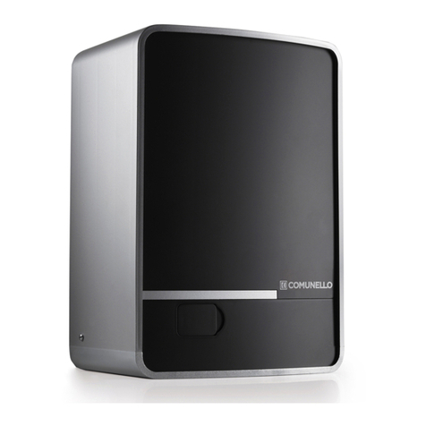
Comunello RAMPART 1000 User manual

RAMPART 600 / 1000
INSTALLATION AND USER’S MANUAL
Electromechanical actuators for
counterbalanced sectional doors
comunello.com
ISTRUZIONI D’USO E DI INSTALLAZIONE
INSTALLATIONS-UND GEBRAUCHSANLEITUNG
INSTRUCIONS D’UTILISATION ET D’INSTALLATION
INSTRUCCIONES DE USO Y DE INSTALACION
ИНСТРУКЦИЯ ПО МОНТАЖУ 91300328 - Rev. 00 - 16/05/2018

2
COMUNELLO ®Copyright 2018 - All rights reserved
FIG. 1
FIG. 2
40÷400
0÷400
2800 mm 500 mm

3
COMUNELLO ®Copyright 2018 - All rights reserved
FIG. 3
FIG. 5 FIG. 6
FIG. 4

4
COMUNELLO ®Copyright 2018 - All rights reserved
FIG. 8FIG. 7
FIG. 9
FIG. 11
FIG. 10
FIG. 10

5
COMUNELLO ®Copyright 2018 - All rights reserved
FIG. 14FIG. 12
FIG. 13
FIG. 15

6
COMUNELLO ®Copyright 2018 - All rights reserved
FIG. 16
FIG. 17
FIG. 18

7
COMUNELLO ®Copyright 2018 - All rights reserved
FIG. 19
TABELLA CONNESSIONI CAVI - AG01 WIRES CONNECTION TABLE AG01
SECTIONAL DOORS (CU 24V RT)
ID Description Cable type Lenght (1m to 20m) Lenght (20m to 50m)
1Main power supply
HAR EN50575
CPR 305/2011
2x1,5mm2 2x2,5mm2
3Flashing light 2x0,5mm2 2x1,0mm2
5A Photocell TX 2x0,5mm2 2x1,0mm2
5B Photocell RX 4x0,5mm2 4x1,0mm2
4 Key selector 3x0,5mm2 3x1,0mm2
2 Antenna RG58 max 20m
1
2
3
4
5A 5B

8
COMUNELLO ®Copyright 2018 - All rights reserved
FIG. 21
370
208 100
123,5
ANTENNA
PULSANTE APRI-CHIUDI (N.O.)
PUSH BUTTON
PULSANTE STOP (N.C.)
STOP BUTTON
ALIMENTAZIONE FOTOCELLULE
PHOTOCELL POWER
24V max 300 mA
ATTENZIONE: Usare Lampeggianti autoscillanti (Art. SWIFT)
FOTOCELLULA
PHOTOCELL
DS (N.C.)
LAMPEGGIANTE - SPIA
FLASHING LIGHT
24V max 5W
INGRESSO
8K2
TR1
TR2
P1
P2

9
COMUNELLO ®Copyright 2018 - All rights reserved
ANTENNA
PULSANTE APRI-CHIUDI (N.O.)
PUSH BUTTON
PULSANTE STOP (N.C.)
STOP BUTTON
ALIMENTAZIONE FOTOCELLULE
PHOTOCELL POWER
24V max 300 mA
ATTENZIONE: Usare Lampeggianti autoscillanti (Art. SWIFT)
FOTOCELLULA
PHOTOCELL
DS (N.C.)
LAMPEGGIANTE - SPIA
FLASHING LIGHT
24V max 5W
INGRESSO
8K2
TR1
TR2
P1
P2

10
COMUNELLO ®Copyright 2018 - All rights reserved
DICHIARAZIONE DI CONFORMITÁ CE
Il sottoscritto, sig. COMUNELLO LUCA rappresentante il seguente costruttore
F.lli COMUNELLO spa
Via Cassola 64, 36027 Rosà (VI) Italy
DICHIARA che l’apparecchiatura descritta in appresso:
Descrizione Automazione elettromeccanica per portoni sezionali
Modello RAMPART 600 - RAMPART 1000
è conforme alle disposizioni legislative che traspongono le seguenti direttive:
• 2014/53/EU (RED) • 2011/65/EU (Direttiva RoHS)
e che sono state applicate tutte le norme e/o speciche tecniche di seguito indicate
EN61000-6-2:2005 + AC:2005
EN61000-6-3:2007 + A1:2011
EN62233:2008
ETSI EN 300 220-1 V3.1.1
ETSI EN 300 220-2 V3.1.1
ETSI EN 301 489-1 V2.1.1
ETSI EN 301 489-3 V2.1.1 Final Draft
EN60335-1:2012+ AC:2014 + A11:2014
ed emendamenti successivi
Inoltre dichiara che non è consentito mettere in servizio il macchinario no a che la macchina in cui sarà incorporata o di cui diverrà
componente sia stata identicata e ne sia stata dichiarata la conformità alle condizioni della Direttiva 2006/42/CE e alla legislazione
nazionale che la traspone.
Rosà (VI) – Italia
13-06-2017
Dr. LUCA COMUNELLO
Legale rappresentante della FRATELLI COMUNELLO s.p.a.
RAMPART 600 / 1000
ISTRUZIONI D’USO E DI INSTALLAZIONE
Fratelli Comunello S.p.A.
Azienda con Sistema Gestione Qualità certicato
UNI EN ISO 9001:2008.
(Certicato n° 50 100 11235 Rev. 02)
11
COMUNELLO ®Copyright 2018 - All rights reserved
ITALIANO
INDICE
1 AVVERTENZE GENERALI
1.1 Avvertenze per la sicurezza
1.2 Avvertenze per l’installazione
1.3 Avvertenze per l’uso
2 MODELLI E DESCRIZIONE PRODOTTO
2.1 Descrizione
2.2 Installazione tipica
3 CARATTERISTICHE TECNICHE DEL PRODOTTO
4 INSTALLAZIONE
4.1 Veriche preliminari
4.2 Limiti d’impiego
4.3 Installazione del motoriduttore RAMPART
4.3.1 Installazione
4.3.2 Installazione necorsa
4.3.3 Sblocco manuale
5 COLLEGAMENTI ELETTRICI
5.1 Regolazioni e collegamento accessori
5.1.1 Riferimenti pannello di controllo e regolazione
5.1.2 Morsetti per il regolamento degli accessori
5.1.3 Apprendimento corsa massima (necorsa elettronico apertura)
5.1.4 Memorizzazione/cancellazione di un radiocomando
5.1.5 Chiusura automatica
5.1.6 Modalità automatica o passo-passo
5.1.7 Regolazione della forza
5.1.8 Ingresso dispositivo di sicurezza 8K2
5.1.9 Ingresso dispositivo fotocellula
5.1.10 Rilevamento ostacoli
5.1.11 Luce di cortesia
5.1.12 Lampeggiante/spia esterni
5.1.13 Selettore a chiave e pulsanti ausiliari
6 COLLAUDO
7 MANUTENZIONE
8 RICAMBI
9 SMALTIMENTO
10 GARANZIA
1 AVVERTENZE GENERALI
1.1 AVVERTENZE PER LA SICUREZZA
Il presente manuale di installazione è rivolto
esclusivamente a personale professionalmente
competente. È necessario leggere tutte le
istruzioni prima di procedere all’installazione.
Tutto quello che non è espressamente previsto in
queste istruzioni non è permesso; usi non previsti
potrebbero essere fonte di danni al prodotto e
mettere in pericolo persone e cose. Il costruttore
declina qualsiasi responsabilità dall’inosservanza
della buona tecnica nella costruzione di serramenti,
nonché delle deformazioni che potrebbero
vericarsi durante l’uso. Conservare questo
manuale anche per utilizzi futuri. La progettazione,
la fabbricazione dei dispositivi che compongono
RAMPART ed il presente manuale rispettano
pienamente la norma vigente. Considerando le
situazioni di rischio che possono vericarsi durante
l’installazione e l’uso di RAMPART e necessario
che anche l’installazione avvenga nel pieno rispetto
di leggi, norme e regolamenti; in particolare:
1.2 AVVERTENZE PER L’INSTALLAZIONE
• Prima di iniziare l’installazione vericare la
necessità di ulteriori dispositivi e materiali che
possono servire a completare l’automazione
con RAMPART in base alla specica situazione
d’impiego.
• L’automatismo non deve essere utilizzato prima
di aver messo in sicurezza il serramento.
• Il materiale dell’imballaggio deve essere smaltito
nel pieno rispetto della normativa locale.
1.3 AVVERTENZE PER L’USO
• Non eseguire modiche su nessuna parte
se non previste nel presente manuale.
Operazioni di questo tipo possono solo causare
malfunzionamento. Il costruttore declina ogni
responsabilità per danni derivati da prodotti
modicati.
• Evitare che le parti dell’automatismo possano
venir immerse in acqua o in altre sostanze
liquide. Anche durante l’installazione evitare
che liquidi possano penetrare all’interno della
centrale e di altri dispositivi aperti.
• Qualora sostanze liquide siano penetrate
all’interno dei dispositivi dell’automatismo,
scollegare immediatamente l’alimentazione
elettrica e rivolgersi al servizio di assistenza;
l’uso di RAMPART in tali situazioni può causare
situazioni di pericolo.
• Non tenere qualsiasi componente di RAMPART
vicino a fonti di calore né esporlo a amme; tali
azioni possono danneggiarlo ed essere causa
di malfunzionamenti, incendio o situazioni di
pericolo.
• Collegare la centrale solo ad una linea di
alimentazione elettrica dotata di messa a terra di
sicurezza.
• Tutte le operazioni che richiedono l’apertura
dei gusci di RAMPART devono avvenire
con la centrale di comando scollegata
dall’alimentazione elettrica; se il dispositivo di
sconnessione non è a vista apporvi un cartello:
“ATTENZIONE MANUTENZIONE IN CORSO”.
• Qualora si verichino interventi di interruttori
automatici o di fusibili, prima di ripristinarli è
necessario individuare ed eliminare il guasto.
• Nel caso di guasto non risolvibile facendo
uso delle informazioni riportate nel presente
manuale, interpellare il servizio di assistenza.
• L’apparecchio non può essere utilizzato da
bambini di età inferiore a 8 anni o da persone
con ridotte capacità siche, sensoriali o mentali,
o prive di esperienza o della necessaria
conoscenza, senza sorveglianza oppure può
essere utilizzato dopo che le stesse abbiano
ricevuto istruzioni relative all’uso sicuro
dell’apparecchio e alla comprensione dei pericoli
ad esso inerenti. I bambini non devono giocare
con l’apparecchio. La pulizia e la manutenzione
destinata ad essere effettuata dall’utilizzatore
non deve essere effettuata da bambini senza
sorveglianza.
• Non permettere ai bambini di giocare con i
controlli dell’automatismo. Tenere i radiocomandi
fuori dalla portata dei bambini. Esaminare
periodicamente l’installazione per vericare la
presenza di eventuali danni ai cavi, molle e parti
meccaniche. Non utilizzare l’automazione se è
necessario un intervento di riparazione.

12
COMUNELLO ®Copyright 2018 - All rights reserved
2 MODELLI E DESCRIZIONE PRODOTTO
2.1 DESCRIZIONE
Attuatore elettromeccanico per porte sezionali bilanciate a molle.
Motoriduttore abbinabile a guide con cinghia o catena di trasmissione,
centrale elettronica di controllo integrata con necorsa elettronici (encoder)
per motore 24V , ricevente radio ad innesto: 433,92 MHz “narrowband”.
2.2 INSTALLAZIONE TIPICA
C
D
B
A
LEGENDA
A MOTORIDUTTORE CON CENTRALINA INTERNA
B FOTOCELLULE IN CHIUSURA
C LAMPEGGIANTE
D SELETTORE A CHIAVE
3 CARATTERISTICHE TECNICHE
DEL PRODOTTO
RAMPART 600 RAMPART 1000
Alimentazione 230V (±10%) / 50Hz
Sforzo di tiraggio massimo (forza neccessaria per la
partenza movimento porta) 600N 1000N
Sforzo di tiraggio nominale (forza neccessaria per
mantenere il movimento della porta) 200N 300N
Peso massimo della porta 110kg 210kg
Velocità massima di apertura 0,14 Metri / secondo
Velocità durante lo sforzo nominale 0,1 Metri / secondo
Tempo massimo motore continuo 60 secondi
(modalità di funzionamento intermittente)
Consumo di energia durante lo sforzo nominale 110 W 150 W
Tempo di illuminazione (tempo LED) dopo l'arresto del
movimento
30 secondi dopo apertura porta
1 minuto dopo chiusura porta
Assorbimento di corrente aggiuntivo (dispositivi esterni) 24V DC / max. 8W (max 300mA)
Corrente assorbita dalla lampada di segnalazione esterna 24V DC / max. 5W (max 200mA)
Radio controllo 433,92MHz / codice dinamico
200 telecomandi max
Tipo di protezione II
Classe di protezione IP20
Range di temperatura -20°C / +50°C
PESO DEL MOTORE 4,5kg 5,0kg
4 INSTALLAZIONE
4.1 VERIFICHE PRELIMINARI
Per un corretto funzionamento dell’automazione vericare quanto segue:
• Tutti gli accessori siano adeguatamente dimensionati.
• La porta, se lasciata libera in ogni posizione, non si muovi da sola.
• Siano rispettati gli spazi minimi e massimi riportati nella FIG. 1.
• Nel caso di portone basculante fare attenzione che il movimento del
portone non vada in contatto con la guida catena (FIG. 2).
• Vericare che nella corsa del portone, sia in chiusura che in apertura,
non ci siano punti di maggiore attrito.
4.2 LIMITI D’IMPIEGO
Prima di eseguire l’installazione del motoriduttore, vericare che i suoi dati
rientrino nei limiti d’impiego nel capitolo 3 “Caratteristiche tecniche del
prodotto”.
4.3 INSTALLAZIONE DEL MOTORIDUTTORE RAMPART
4.3.1 INSTALLAZIONE:
• Predisporre i due pezzi di guida per essere assemblati (saltare questo
punto nel caso di unico pezzo).
• Far scorrere all’interno delle guide la testa con puleggia FIG. 3.
• Unire i due pezzi di guida mediante l’utilizzo del giunto come da FIG. 4
(saltare questo punto nel caso di guida unico pezzo).
• Portare la testa con ingranaggio all’estremità della guida ed assemblare
il tirante con molla alla guida stessa (FIG. 5).
• Serrare il dado in dotazione contro la molla no ad ottenere una tensione
sufciente della catena/cinghia (FIG. 6).
• Assemblare la leva di traino e la staffa di ssaggio al portone con il
carrello della guida (può essere utilizzato solo la leva “A”) (FIG. 7).
• Inlare la staffa di supporto guida lungo la guida stessa (FIG. 8).
• Fissare l’attuatore alla guida mediante le viti e le staffe in dotazione (FIG. 9).
• Fissare le staffe di sostegno alla staffa di supporto guida (FIG.10). I piatti
forati possono essere tagliati a seconda della lungheza necessaria. Nel
caso di ssaggio diretto a softto non utilizzare i piatti forati.
• Fissare la staffa anteriore sopra il portone in posizione centrale (FIG. 11).
• Assemblare la guida alla staffa anteriore sopra il portone mediante perno
e copiglia in dotazione (FIG.12).
• Fissare la guida a softto come illustrato nelle FIG. 13 e 14.
• Fissare la leva di traino al portone mediante perno e copiglia in dotazione
(FIG. 15).
• Legare il cordino di attivazione dello sblocco manuale (FIG.16).
4.3.2 REGOLAZIONE FINECORSA
• Svitare e posizionare il necorsa nella posizione desiderata FIG. 17.
• Bloccare il ne corsa serrando la vite.
4.3.3 SBLOCCO MANUALE
• Per sbloccare e consentire un movimento manuale del portone
tirare il cordino legato al carrello scorrevole lungo la guida (FIG.18).
• Il portone può essere movimentato manualmente.
5 COLLEGAMENTI ELETTRICI
L’attuatore viene fornito con cavo di alimentazione predisposto al
collegamento su quadro elettrico (opportunamente protetto). Per il
collegamento degli accessori (pulsanti, selettori, fotocellule...) si veda il
seguente paragrafo (FIG. 19).
• Utilizzare in fase di installazione esclusivamente
cavi in doppio isolamento (cavi con guaina) sia
per i collegamenti a tensione di rete (230V) che
per i collegamenti in bassissima tensione di
sicurezza SELV (lampeggiante, fotocellule).
• Il doppio isolamento dei cavi deve essere
mantenuto sino alle immediate vicinanze
dei morsetti sguainandoli esclusivamente
nelle immediate vicinanze delle morsettiere e
dovranno essere vincolati anche da fascette.
• Utilizzare in fase di installazione esclusivamente
canalette in plastica.
• Utilizzare canalette distinte per i cablaggi in bassa
tensione (230V) e per i cablaggi in bassissima
tensione di sicurezza (SELV).
• “I conduttori a bassissima tensione di sicurezza,
devono essere sicamente separati (almeno
4mm in aria) dai conduttori a tensione di rete,
oppure devono essere adeguatamente isolati
con isolamento supplementare avente spessore
di almeno 1 mm.

13
COMUNELLO ®Copyright 2018 - All rights reserved
ITALIANO
• Utilizzare cavi FG7 2x1,5 mm2come cavo di
alimentazione o di categoria superiore.
• Prevedere a monte della rete di alimentazione
dell’automazione un dispositivo che assicuri la
disconnessione completa onnipolare dalla rete
(con categoria III di sovratensione e con una
distanza di apertura dei contatti in ciascun polo
di almeno 3 mm), conformemente alle regole di
installazione e direttamente collegato ai morsetti
di alimentazione.
5.1 REGOLAZIONI E COLLEGAMENTO ACCESSORI
5.1.1 RIFERIMENTI PANNELLO DI CONTROLLO E REGOLAZIONE
F1: Fusibile di protezione alimentazione di rete 230V~(F3.15A250V).
F2: Fusibile di protezione alimentazione motore 24V (F15A250V).
FORCE (TR1): Regolazione FORZA (forza massima in senso orario).
AUTO (TR2): TEMPO CHIUSURA AUTOMATICA (incremento
tempo in senso orario)
P1: Pulsante per memorizzazione radiocomandi.
P2: Pulsante per apprendimento corsa massima.
S1: Selettore modalità PASSO-PASSO (apre-stop-chiude) o
AUTOMATICO (apre-chiude)
S2: Selettore per inversione senso rotazione motore .
LED1: Led di segnalazione (feedback) presenza tensione.
LED2: Led di segnalazione (feedback) per programmazione corsa massima.
LED3: Led di segnalazione (feedback) per memorizzare / cancellare i
radiocomandi.
5.1.2 MORSETTI PER IL COLLEGAMENTO DEGLI ACCESSORI (CN1)
1. GND (comune)
2. Ingresso pulsante Apre/Chiude (N.A.)
3. Ingresso pulsante Stop (N.C.)
4. Ingresso Dispositivo di Sicurezza Fotocellule (N.C.)
5. Alimentazione 24V + Dispositivo di Sicurezza Fotocellule (max 300mA)
6. Alimentazione 24V - Dispositivo di Sicurezza Fotocellule
7. Alimentazione 24V + Lampeggiante (max 5W)
8. Alimentazione 24V - Lampeggiante
9. Ingresso Antenna (polo caldo)
10. GND (comune)
11. Ingresso Dispositivo di Sicurezza 8K2
5.1.3 APPRENDIMENTO CORSA MASSIMA
(FINECORSA ELETTRONICO APERTURA).
Per impostare la Corsa Massima FEA (Finecorsa Elettronico in Apertura), è
necessario che il motore sia collegato al sezionale tramite il relativo binario
e che il pattino di traino sia agganciato alla catena (o cinghia). È necessario
inoltre che sia collegato almeno un pulsante di comando (o sia presente
un radiocomando memorizzato) e i dispositivi di sicurezza (Fotocellula e
Ingresso STOP) attivi e N.C. Per acquisire il FEA, alimentare il motore,
posizionare il sezionale su una posizione “quasi chiusa” (circa
500mm dalla battuta di chiusura) agendo sul pulsante di comando o
sul radiocomando. Premere e tener premuto il pulsante P2 sul quadro
di comando no a che il led di segnalazione LED2 si accende; rilasciare
il pulsante P2 (il LED2 inizia a lampeggiare). Il sezionale comincerà una
manovra di chiusura no alla battuta. Una volta chiuso (acquisizione della
posizione di Zero) inizierà la manovra di apertura a bassa velocità: quando il
sezionale avrà raggiunto la posizione desiderata di apertura (FEA) premere
nuovamente il tasto P2, il sezionale si ferma nella posizione di tutto aperto
(corsa massima). Alternativamente è possibile lasciare che la corsa termini
su un eventuale blocco meccanico (inserito nel binario) acquisendo
ugualmente il FEA (FIG. 17). Successivamente il motore effettua una
manovra di chiusura in automatico. Il LED2 smette di lampeggiare e poi si
spegne confermando l’avvenuta memorizzazione della corsa massima. La
procedura di acquisizione FEA può essere effettuata nuovamente, se
necessario, solo con il motore alimentato in posizione di Stop
5.1.4 MEMORIZZAZIONE / CANCELLAZIONE DI UN RADIOCOMANDO
Per memorizzare un radiocomando (trasmettitore Radio COMUNELLO) è
sufciente agire sul pulsante P1 del pannello di controllo, con la seguente
logica di gestione:
Canale 1: Premere una volta il pulsante P1, il LED3 lampeggia con ash
singolo. Premere il tasto del trasmettitore che si desidera
programmare con la funzione APRI-CHIUDI.
Canale 2: Premere due volte il pulsante P1, il LED3 lampeggia con due
ash. Premere il tasto del trasmettitore che si desidera
programmare con la funzione di STOP.
Reset: Premere 4 volte il pulsante P1, il LED3 si accende a luce
ssa. Premere e tener premuto il tasto P1, il LED3 lampeggia
velocemente, mantenere premuto il tasto P1 no a che il LED3
smette il lampeggio (conferma avvenuta cancellazione dei
radiocomandi memorizzati).
5.1.5 CHIUSURA AUTOMATICA
Il motore è dotato di Chiusura Automatica inseribile. Per abilitare o disabilitare
la Chiusura Automatica agire sul Trimmer TR2 nel seguente modo:
SELEZIONE TEMPO CHIUSURA AUTOMATICA
0% = Chiusura Automatica DISABILITATA
50% = 3"
75% = 30"
100% = 60"
Nota = incremento in senso orario.
Impostazione di fabbrica: Chiusura Automatica abilitata.(30")
5.1.6 MODALITÀ AUTOMATICA O PASSO-PASSO
Le modalità di controllo del movimento disponibili sono due: Modalità
Automatica (ad ogni pressione del pulsante Apri-Chiudi o del Radiocomando
il motore inverte il moto) o Passo-Passo (ad ogni pressione del pulsante
Apri-Chiudi o del Radiocomando il motore esegue ciclicamente la manovra
Apri-Stop-Chiudi-Stop). Per selezionare la modalità desiderata, agire sul
selettore S1:
S1 in ON Modalità Passo-Passo abilitata.
S1 in OFF Modalità Automatica abilitata.
5.1.7 REGOLAZIONE DELLA FORZA
La regolazione della Forza avviene tramite il trimmer TR1. Regolando in
senso orario si aumenta la forza di trazione (in senso antiorario si diminuisce
e il sistema diventa più sensibile al rilevamento degli ostacoli).
5.1.8 INGRESSO DISPOSITIVO DI SICUREZZA 8K2 (M10-M11)
L'ingresso del dispositivo di sicurezza 8k2 permette l'uso di coste resistive
8k2 che, alla loro attivazione, invertono brevemente il movimento in chiusura
e apertura (rimanendo in attesa di un comando).
ATTENZIONE: la centrale verica in fase di programmazione della corsa
massima il tipo di impedenza in ingresso al morsetto 8k2-GND (es. N.O.,
N.C. o 8k2 ohm) e gestisce il dispositivo di sicurezza di conseguenza.
Al termine della programmazione della corsa, vericare sempre la corretta
attivazione dell'ingresso del dispositivo di sicurezza collegato.
5.1.9 INGRESSO DISPOSITIVO FOTOCELLULA (M1-M4)
L'ingresso del dispositivo di sicurezza fotocellula gestisce una fotocellula
(N.C.) attiva in chiusura effettuando l'inversione totale del movimento
(ed impedendo la chiusura). Nella posizione di serramento chiuso, se
intercettata, impedisce l'apertura (rilevamento ostacolo da chiuso).
5.1.10 RILEVAMENTO OSTACOLI
Il motore è dotato di un sistema di rilevamento ostacoli attivo durante la
corsa normale. Tramite l’uso di un encoder digitale, quando un ostacolo
interrompe la normale corsa del sezionale, il motore viene bloccato al
superamento della forza di impatto prevista dalla normativa invertendo
brevemente la marcia e rimanendo in STOP no alla ricezione del comando
successivo.
NOTA: Il sistema di controllo dispone di una autoregolazione periodica dei
proli di soglia di intervento ostacolo in modo da compensare l'eventuale

14
COMUNELLO ®Copyright 2018 - All rights reserved
progressiva perdita di bilanciamento della struttura.
5.1.11 LUCE DI CORTESIA
All’interno del motore è presente una luce di cortesia a LED (2W, luce
ssa) che si attiva ad ogni manovra rimanendo accesa per circa 30 sec
dopo ogni apertura (o STOP) e 60 sec dopo ogni chiusura (completa). Tale
funzione è sempre presente e non è disattivabile.
5.1.12 LAMPEGGIANTE / SPIA ESTERNI
Se è necessario collegare un lampeggiante o spia esterni, è possibile
utilizzare gli appositi morsetti di alimentazione dedicati (Pannello di comando:
M7-M8). L’uscita di questi morsetti fornisce una tensione continua (28V
) con assorbimento massimo prelevabile di circa 150mA.
NOTA: La tensione in uscita è costante, utilizzabile quindi per alimentare
una lampada spia di opportuna potenza. Nel caso si desideri alimentare
un lampeggiante è necessario utilizzare lampeggianti autoscillanti
(autolampeggianti) (SWIFT).
5.1.13 SELETTORE A CHIAVE E PULSANTI AUSILIARI
Nel caso sia necessario cablare dei pulsanti di comando ausiliari (es:
selettori a chiave), è possibile collegarli in parallelo agli ingressi dedicati
(morsetti M1-M2 comando Apri-Chiudi e morsetti M1-M3 comando Stop).
6 COLLAUDO
Ogni singolo elemento dell’automatismo, ad esempio bordi sensibili,
fotocellule, arresto di emergenza, ecc. richiede una specica fase di
collaudo; per questi dispositivi si dovranno eseguire le procedure riportate
nei rispettivi manuali istruzioni. Per il collaudo di RAMPART eseguire la
seguente sequenza di operazioni:
• Vericare che sia stato rispettato rigorosamente tutto quanto previsto nel
presente manuale ed in particolare nel capitolo 1 “Avvertenze Generali”.
• Utilizzando i dispositivi di comando o arresto previsti (selettore a
chiave, pulsanti di comando o trasmettitori radio), effettuare delle prove
di apertura, chiusura ed arresto del cancello e vericare che il
comportamento corrisponda a quanto previsto.
• Vericare uno ad uno il corretto funzionamento di tutti i dispositivi di
sicurezza presenti nell’impianto (fotocellule, bordi sensibili, arresto di
emergenza, ecc.).
7 MANUTENZIONE
La manutenzione deve essere effettuata regolarmente da parte di personale
qualicato secondo quanto previsto dalle leggi e normative vigenti. Per
RAMPART è necessaria una manutenzione programmata al massimo entro
6 mesi o 10.000 manovre dalla precedente manutenzione.
• Scollegare qualsiasi fonte di alimentazione dal motore.
• Vericare e sotituire tutte le parti di movimento usurate.
• Vericare lo stato di deterioramento di tutte le parti dell’automazione.
8 RICAMBI
È possibile acquistare dei particolari di ricambio, in caso di tale necessità
contattare l’assistenza tecnica.
9 SMALTIMENTO
Al termine della vita dell’automazione, assicuratevi che lo smantellamento
sia eseguito da personale qualicato e che i materiali vengano riciclati o
smaltiti secondo le norme valide a livello locale.
10 GARANZIA
a) La presente garanzia nei rapporti commerciali o in caso di vendita di
beni per uso professionale è limitata alla riparazione o sostituzione del
pezzo del Prodotto riconosciuto da FRATELLI COMUNELLO SPA quale
difettoso mediante Prodotti rigenerati equivalenti (di seguito “Garanzia
Convenzionale”), non risulta compresa nella garanzia il costo necessario per
le attività di riparazione e sostituzione del materiale (a titolo esemplicativo
costi di manodopera, noleggio materiali, etc).
b) E’ esclusa l’applicazione della disciplina dettata dagli articoli 1490-1495
del Codice Civile.
c) FRATELLI COMUNELLO SPA garantisce il funzionamento dei Prodotti
nei limiti indicati al superiore punto sub a). Salvo diverso accordo, la validità
della Garanzia Convenzionale è di 24 (ventiquattro) mesi dalla data di
produzione, rilevabile sui Prodotti. La Garanzia risulterà efcace e vincolante
per COMUNELLO solo se il prodotto verrà correttamente montato e
manutentato in conformità alle regole di installazione e di sicurezza indicate
nella documentazione fornita da COMUNELLO o comunque rinvenibile sul
sito http://www.comunello.com/it/corporate/condizioni-generali/
d) La garanzia non comprende: avarie o danni causati dal trasporto; avarie
o danni causati da vizi dell’impianto elettrico presente presso l’acquirente il
prodotto e/o da trascuratezza, negligenza, inadeguatezza, uso anomalo di
tale impianto; avarie o danni dovuti a manomissioni poste in essere da parte
di personale non autorizzato o conseguenti allo scorretto uso/installazione
(a questo proposito, si consiglia una manutenzione del sistema almeno
ogni sei mesi) o all’impiego di pezzi di ricambio non originali; difetti causati
da agenti chimici e/o fenomeni atmosferici. La garanzia non comprende
il costo per materiale di consumo, in ogni caso COMUNELLO matura il
credito per l’intervento eseguito presso il cliente, laddove quest’ultimo si
riveli inutile poiché non risultava operante la garanzia o perché il cliente
aveva utilizzato il prodotto COMUNELLO in modo negligente, imprudente
od imperito, tale per cui il corretto utilizzo del prodotto avrebbe potuto
evitare l’installazione.
e) Termini attuativi: salvo diverso accordo, il diritto alla Garanzia Convenzionale
si esercita esibendo copia del documento di acquisto (fattura scale) a
COMUNELLO. Il Cliente deve denunciare il difetto a COMUNELLO entro il
termine di decadenza di 30 (trenta) giorni dalla scoperta.
L’azione deve essere esercitata entro il termine di prescrizione di 6 (sei)
mesi dalla scoperta. I pezzi dei Prodotti per i quali viene richiesta l’attivazione
della Garanzia Convenzionale devono essere spediti dal Cliente presso
FRATELLI COMUNELLO SPA, Via Cassola 64, 36027 Rosà (VI) Italia.
f) Il Cliente non potrà richiedere il risarcimento di danni indiretti, mancati
protti, perdita di produzione ed in ogni caso non potrà pretendere a titolo di
risarcimento somme superiori al valore dei componenti o dei Prodotti forniti.
Tutte le spese per il trasporto dei Prodotti da riparare o riparati, anche se
coperti dalla Garanzia Convenzionale, sono a carico del Cliente.
g) Nessun intervento esterno effettuato dal personale tecnico di
COMUNELLO è coperto dalla Garanzia Convenzionale.
h) Modiche speciche delle condizioni della Garanzia Convenzionale qui
descritte possono essere denite dalle parti nei propri contratti commerciali.
i) In caso di controversia legale di qualsiasi natura è applicabile il diritto
italiano ed è competente il Foro di Vicenza.

15
COMUNELLO ®Copyright 2018 - All rights reserved
ENGLISH
RAMPART 600 / 1000
INSTALLATION AND USER’S MANUAL
Fratelli Comunello S.p.A.
Company with certied Quality Management System
UNI EN ISO 9001:2008.
(Certicate n° 50 100 11235 Rev. 02)
EC DECLARATION OF COMFORMITY:
The undersigned Mr. Luca Comunello, representing the following manufacturer,
Fratelli COMUNELLO Spa
Via Cassola 64, 36027 Rosà (VI) – Italy
DECLARES that the equipment described below:
Description: Electromechanical operator for sectional doors
Model: RAMPART 600 - RAMPART 1000
Is in compliance with the provisions set down in the following directives:
• 2014/53/EU (RED) • 2011/65/EU (RoHS Directive)
and that all the rules and/or technical specications shown below have been applied:
EN61000-6-2:2005 + AC:2005
EN61000-6-3:2007 + A1:2011
EN62233:2008
ETSI EN 300 220-1 V3.1.1
ETSI EN 300 220-2 V3.1.1
ETSI EN 301 489-1 V2.1.1
ETSI EN 301 489-3 V2.1.1 Final Draft
EN60335-1:2012+ AC:2014 + A11:2014
and the following amendments.
and he also declares that it is not allowed to commission the device until the machinery where it will be incorporated or whose it will
become a component will have been identied and will have been declared in compliance with the conditions of the 2006/42 EC Directive
and with the national legislation that transpose it.
Rosà (VI) – Italia
13-06-2017
Mr. Luca Comunello
Fratelli Comunello Legal Representative

16
COMUNELLO ®Copyright 2018 - All rights reserved
CONTENTS
1 GENERAL PRESCRIPTIONS
1.1 Safety prescriptions
1.2 Installation prescriptions
1.3 Operating prescriptions
2 MODELS AND PRODUCTS DESCRIPTION
2.1 Description
2.2 Typical installation
3 PRODUCT TECHNICAL SPECIFICATIONS
4 INSTALLATION
4.1 Preliminary checks
4.2 Operating limits
4.3 Installing the RAMPART operator
4.3.1 Installation
4.3.2 Installation of limit stops and switches
4.3.3 Operator manual release
5 ELECTRICAL CONNECTIONS
5.1 Settings and connection of accessories
5.1.1 Control and adjustment panel references
5.1.2 Terminals for control of accessories
5.1.3 Maximum travel learning (opening electronic limit switch)
5.1.4 Saving/deleting a remote control
5.1.5 Automatic closing
5.1.6 Automatic or step-by-step mode
5.1.7 Force adjustment
5.1.8 8K2 security device input
5.1.9 Photocell input
5.1.10 Obstacles detection
5.1.11 Courtesy light
5.1.12 External ashing light/indicator light
5.1.13 Key selector switch and auxiliary pushbuttons
6 TESTING
7 PRODUCT MAINTENANCE
8 SPARE PARTS
9 DISPOSAL
10 WARRANTY
1 GENERAL PRESCRIPTIONS
1.1 SAFETY PRESCRIPTIONS
This installation manual is addressed exclusively
to professionally skilled personnel. Read all
the instructions carefully before starting the
installation procedures. Any operations that are
not expressly set down in these instructions
are to be considered prohibited; improper use
may result in damage to the product and place
persons and property at risk. The manufacturer
declines all liability for the failure to observe
best practices in door construction and for any
possible deformation that may occur during
use of the product. Store this manual in a safe
place for future reference. The design and
construction of the devices of which model
RAMPART is composed and this manual are in
full compliance with statutory legislation.
In consideration of potential hazards that
may arise during the installation and use of
RAMPART, the installation procedures must be
carried out in full compliance with the applicable
laws, standards and regulations; namely:
1.2 INSTALLATION PRESCRIPTIONS
• Before starting the installation procedures
make sure you have any additional devices
and materials that may be required to complete
the automation system with RAMPART in
consideration of the specic application.
• The automation system must not be used
until the door has been made safe.
• Dispose of packaging materials in compliance
with local regulations.
1.3 OPERATING PRESCRIPTIONS
• No modications can be made to any part of
the product unless specied in this manual.
Unauthorized modication of the product is
likely to lead to malfunctions. The manufacturer
declines all liability for damage caused by
unauthorized modications.
• The parts of the automation system must
never be immersed in water or other liquids.
During the installation procedures ensure that
no liquids penetrate inside the control unit or
other open devices.
• If liquids penetrate any parts of the automation
system disconnect the electrical power
supply immediately and consult Comunello
technical service; the use of RAMPART in
such conditions may give rise to potentially
hazardous situations.
• Keep all parts of the RAMPART automation
system away from heat sources and open
ames; exposure to heat or ames may
damage the devices and cause faults, re, or
hazardous situations.
• When the equipment remains unused for a
long time, remove the optional battery and
store it in a dry place to avoid the risk of
leakage of harmful substances.
• Connect the control unit exclusively to an
electric power supply line equipped with an
efcient protective earth conductor.
• Any operations that require the housing of
RAMPART to be opened must be performed
with the control unit disconnected from the
electrical power supply; if the disconnect
device is not clearly visible from where you are
working, attach a warning notice to the effect:
"WARNING - MAINTENANCE IN PROGRESS”.
• In the case of tripping of circuit breakers or
blowing of fuses, nd the fault and remedy it
before resetting the circuit breaker or changing
the fuse.
• If the fault cannot be remedied using the
information given in this manual, consult
technical service.
• The device can’t be used by children
younger than 8 years of age and by people
with reduced physical, sensory or mental
capabilities, or without experience or the
required knowledge if not under surveillance
or after having received instructions about the
safe use of the device and the inherent risks
in it. Children should not play with the device.
Cleaning and maintenance should not be
carried out by children without surveillance.
• Children can’t play with the commands of
the automatism. Remote controls should be

17
COMUNELLO ®Copyright 2018 - All rights reserved
ENGLISH
kept out of reach of children. It is suggested
to periodically examine the installation in order
to verify the presence of possible damages
to the cables, springs and mechanical
parts. Automation should not be used if it is
necessary a repair intervention.
2 MODELS AND PRODUCTS DESCRIPTION
2.1 DESCRIPTION
Electromechanical operator for spring balanced sectional doors.
Operator designed for coupling to tracks with a drive belt or chain, built-
in electronic control unit with electronic limit stops (encoder) for 24V
motor, plug-in radio receiver: 433.92 MHz narrowband.
2.2 TYPICAL INSTALLATION
C
D
B
A
KEY
A OPERATOR WITH BUILT-IN CONTROL UNIT
B CLOSING PHOTOCELLS
C FLASHING LIGHT
D KEY SELECTOR SWITCH
3 TECHNICAL SPECIFICATIONS
RAMPART 600 RAMPART 1000
Power 230V (±10%) / 50Hz
Maximum pulling effort (force needed to start door move) 600N 1000N
Nominal pulling effort (force needed to maintain door move) 200N 300N
Maximum door leaf weight 110kg 210kg
Maximum opening speed 0,14 meters/seconds
Speed during nominal effort 0,1 meters/seconds
Maximum continuous motortime 60 seconds (intermittent operation mode)
Power consumption during nominal effort 110 W 150 W
Light time (LED-time) after movement stop 30 seconds after opening the door
1 minute after closing the door
Current consumption of additional (external devices) 24V DC / max. 8W (max 300mA)
Current consumption of external signal Lamp 24V DC / max. 5W (max 200mA)
Radiocontrol 433,92MHz / dynamic code
200 remotes max
Protection type II
Protection class IP20
Temperature range -20°C / +50°C
Drive weight (net) 4,5kg 5,0kg
4 INSTALLATION
4.1 PRELIMINARY CHECKS
For correct operation of the automation system, make sure:
• All the accessories are suitably sized.
• The door does not move autonomously when released in any
position.
• The minimum and maximum clearances shown in gure 1 are
complied with
• In the case of up-and-over doors ensure that the door panel does
not interfere with the chain track. (FIG. 2).
• There are no points of stiffness throughout the entire opening or
closing travel of the door.
4.2 APPLICATION LIMITS
Before installing the operator check that its specications are within
the application limits shown in the chapter “Product Technical
Specications”.
4.3 INSTALLING THE RAMPART OPERATOR
4.3.1 INSTALLATION:
• Arrange the two track sections for assembly. (skip this step if the track
is supplied in a single length).
• Slide the drive head with sprocket into the track FIG. 3.
• Join the two track sections using the joint as shown in FIG. 4 (skip
this step if the track is supplied in a single length).
• Bring the terminal with sprocket to the end of the track and t the
tensioner with spring to the track (FIG. 5).
• Tighten the supplied nut against the spring until the chain/belt is
sufciently taut (FIG. 6).
• Fit the drive lever and xing bracket to the door with the guide trolley
(lever "A" alone may be used) (FIG. 7).
• Insert the track support bracket over the track (FIG. 8).
• Secure the operator to the track using the screws and brackets
supplied (FIG. 9).
• Secure the support brackets to the track holder bracket (FIG.10).
The drilled plates can be cut to the required length. In the case of
direct ceiling mounting, do not use the supplied brackets.
• Fix the front bracket in a central position above the door. (FIG. 11).
• Assemble the track and front bracket xed above the door using the
supplied pin and cotter (FIG.12).
• Fix the track to the ceiling as shown in FIG. 13 and 14.
• Secure the drive lever to the door using the supplied pin and cotter
(FIG.15).
• Tie on the manual release cord (FIG.16).
4.3.2 LIMIT STOP ADJUSTMENT
• Undo the limit stop and bring it to the required position FIG. 17.
• Lock the limit stop in position by tightening the screw.
4.3.3 MANUAL RELEASE
• To release the door and allow it to be opened and closed manually
pull the cord tied to the sliding trolley in the guide track. (FIG.18).
• The door can now be moved manually .
5 ELECTRICAL CONNECTIONS
The operator is supplied with a power cable for connection to the
mains switchboard (suitably protected). For connection of accessories
(pushbuttons, selectors, photocells...) refer to the following heading
(FIG. 19).
• Use only double insulated cables (sheathed
cables) during the installation phase for both
the connections in AC voltage (230 V) and
the ones in SELV safety extreme low voltage
(ashing, photocells).
• Double insulation of cables has to be
maintained up to the immediate proximity of
terminals, unsheathing them exclusively in
proximity of terminals and they will have to be
bonded by cable ties.
• Use only plastic raceways during the installation
phase.
• Use separate raceways for the low voltage
wirings (230 V) and for the ones in SELV safety
extreme low voltage.
• Safety extreme low voltage conductors have
to be physically separated (at least 4 mm up
in the air) from the ones in AC voltage, or they
have to be adequately isolated with additional
insulation with a thickness of at least 1 mm.
• Use FG7 2x1,5 mm2 cables or an higher
category as power cord.

18
COMUNELLO ®Copyright 2018 - All rights reserved
• Provide upstream of the mains supply of the
automation a device that can assure an all-
pole disconnection from the electrical grid
(with the 3rd category of overvoltage and with
an opening distance of the contacts in each
pole of at least 3 mm), in compliance with the
installation rules and directly connected to the
power supply terminals.
5.1 SETTINGS AND CONNECTION OF ACCESSORIES
5.1.1 CONTROL AND ADJUSTMENT PANEL REFERENCES
F1: 230V~mains power supply fuse (F3.15A250V).
F2: 24V operator power supply fuse (F15A250V).
FORCE (TR1): FORCE control (clockwise for maximum force).
AUTO (TR2): Auto closing time (time increase in clockwise
direction).
P1: Remotes acquisition button.
P2: Maximum travel learning button.
S1: Auto (open-close) or step-by-step mode (open-stop-close) key selector
switch.
S2: Key selector switch to invert motor sense rotation
POWER LED: 2W LED courtesy light.
LED1: Power indicator LED (feedback).
LED2: Maximum travel programming indicator LED (feedback).
LED3: Remotes save/delete indicator LED (feedback).
5.1.2 ACCESSORIES CONNECTION TERMINALS (CN1)
1: GND (common).
2: Open/Close Pushbutton input (NO).
3: Stop Pushbutton input (NC).
4: Photocells Safety Input (NC).
5: 24V + Power Supply for Photocells Safety (max 300mA).
6: 24V – Power Supply for Photocells Safety.
7: 24V + Power Supply for Flashing Light (max 5W).
8: 24V – Power Supply for Flashing Light.
9: Antenna Input (signal pole).
10: GND (common).
11: 8K2 Safety Input.
5.1.3 MAXIMUM TRAVEL LEARNING (OPENING LIMIT SWITCH)
To set the Opening Limit Switch the operator must be coupled to the door
via the track and the sliding runner must be attached to the drive chain or
belt. In addition, at least one pushbutton control must be connected to the
system (or a saved remote must be available) and activated secutiry devices
(photocells and STOP enter) and N.C. (normally closed) To acquire the
Opening Limit Switch position: power the operator, bring the door to
a "nearly closed" position (approximately 500 mm from the closing
stop) by means of the pushbutton or button on the remote. Press and hold
down button P2 on the control panel until LED2 comes on; release button
P2 (LED2 starts blinking). The door will perform a closing movement until
reaching the end stop. Once the door is closed (Zero position acquisition) it
will start the opening movement at low speed; when the door reaches the
required opening position (Opening Limit Switch) press P2 again: the door will
stop in the fully open position (maximum travel). Alternately, you can allow the
door travel to reach the mechanical end stop (if tted in the guide track) and
still acquire the Opening Limit Switch position. The operator will subsequently
perform an automatic closing cycle, LED2 will stop blinking and then switch
off, thereby conrming that the maximum travel position has been saved.
The Opening Limit Switch acquisition procedure can be repeated, if
necessary, only with the operator powered in the stop position.
5.1.4 SAVING / DELETING A REMOTE
To save a remote (Comunello radio transmitter) simply press button P1 on the
control panel. Management logic is as follows:
Channel 1: Press button P1 once, LED3 blinks once. Press the remote
button to which you wish to assign the OPEN-CLOSE function.
Channel 2: Press button P1 twice, LED3 blinks twice. Press the remote
button to which you wish to assign the STOP function.
Reset: Press button P1 four times, LED3 will switch on steady.
Press and hold down button P1, LED3 blinks rapidly; keep
button P1 pressed until LED3 stops blinking (conrmation that
the saved remotes have been deleted).
5.1.5 AUTOMATIC CLOSING
The operator features a selectable Automatic Closing function. To
enable or disable Automatic Closing set the Trimmer TR2 as follows:
AUTO CLOSING TIME SELECTION
0% = Auto closing disabled
50% = 3"
75% = 30"
100% = 60"
Note= Increase in clockwise direction
Factory setting: Automatic Closing enabled.(30")
5.1.6 AUTOMATIC OR STEP-BY-STEP MODE
There are two movement control modes available: Automatic Mode
(each time the Open-Close button or Remote button is pressed the
operator reverses its direction of run) or Step-by-Step (each time the
Open-Close button or Remote button is pressed the operator performs
the Open-Stop-Close-Stop movement in sequence). Set the required
operating mode with selector S1:
S1 ON Step-by-Step Mode enabled
S1 OFF Automatic Mode enabled
5.1.7 FORCE ADJUSTMENT
The operator Force can be adjusted using trimmer TR1. Turning the
trimmer clockwise increases driving force (by turning the trimmer counter
clockwise it decrease and the system becomes more sensitive to the
obstacle detection). Factory setting: Minimum Force.
5.1.8 8K2 SECURITY DEVICE INPUT (M10-M11)
The 8K2 safety device input allows the use of 8k2 resistive safety edges
which brefely reverse the movement both when opening and closing (it
remains in standby until a given input).
ATTENTION: During the programming phase, the control unit checks the
type of maximum impedance at the input of terminal 8k2-GND (for ex. N.O.,
N.C. or 8k2 ohms) and manages the safety device accordingly. At the end
of the stroke programming, always check the correct activation of the input
of the connected safety device.
5.1.9 PHOTOCELL INPUT (M1-M4)
The entrance of the photocell safety device manages a photocell (N.C.)
which activates during closing, carrying out total inversion of the movement
(and preventing closure).
In the closed door position, if the photocell is intercepted, it prevents
opening (obstacle detection when closed)."
5.1.10 OBSTACLES DETECTION
The operator is equipped with a system for the detection of obstacles
during its normal travel movements. By means of a digital encoder, when
the normal travel of the door is obstructed the operator is stopped once
the impact force prescribed by the applicable standards is exceeded;
the operator then performs a short reverse movement and remains in
STOP status until it receives a new command.
NOTE= the control system has a periodic autoregulation of obstacle
intervention threshold proles In order to make up for the possible
progressive loss of balancing of the structure.
5.1.11 COURTESY LIGHT
The operator is equipped with an internal LED courtesy light (2W,
steady on) that switches on with each movement and remains on for
approximately 30 seconds after the Open (or close) and 60 sec after
every closing (total). This function is always on and cannot be overridden.
5.1.12 EXTERNAL FLASHING LIGHT/INDICATOR LIGHT
If an external ashing light or indicator light is required, use the dedicated
power supply terminals (Control panel: M7-M8). These terminals provide
a dc output (28V ) with maximum current draw of approximately
150mA.
NOTE: The output voltage is constant and can therefore be used to
power a suitably rated indicator light. If a ashing light is to be connected
it must be of the self-ashing type (SWIFT).

19
COMUNELLO ®Copyright 2018 - All rights reserved
ENGLISH
5.1.13 KEY SELECTOR SWITCH AND AUXILIARY PUSHBUTTONS
If auxiliary controls are to be wired into the system (e.g. key selector
switches) they can be connected in parallel with the dedicated inputs
(Open-Close command terminals M1-M2 and Stop command terminals
M1-M3).
6 TESTING
Each part of the automation system, e.g. safety edges, photocells,
emergency stop, etc. must be tested; follow the procedures shown in
the instruction manuals supplied with the devices in question. Perform
the following sequence of operations for testing of RAMPART:
• Check that all the prescriptions in this manual have been followed
scrupulously, with special attention to the matters set down in
chapter 1 "General Prescriptions".
• Using the supplied control or stopping devices (key selector switch,
pushbuttons or remotes), perform door opening, closing and
stopping tests and make sure the door responds correctly to the
various commands.
• Check operation of all the system's safety devices (photocells, safety
edges, emergency stop, etc.) one by one.
7 MAINTENANCE
Maintenance must be carried out at regular intervals by qualied
personnel in compliance with the provisions of statutory legislation and
the regulations in force. RAMPART must be serviced at least once every
6 months or after 10.000 operating cycles since the last service.
• Disconnect the operator from all power supplies.
• Check all the moving parts and replace any worn parts.
• Check all parts of the automation system for signs of deterioration.
8 SPARE PARTS
Spare parts can be purchased by contacting technical service.
9 DISPOSAL
At the end of its useful life the automation system must be dismantled
by qualied personnel and the materials must be recycled or disposed
of in compliance with the local legislation in force.
10 WARRANTY
a) In business relationships or in case of products sold for professional
use, this warranty is limited to the repair or replacement of product parts
that FRATELLI COMUNELLO SPA acknowledges as defective, through
equivalent re-manufactured Products (the "Conventional Warranty"); the
warranty does not include the costs necessary for repairing or replacing
the material (e.g. labour costs, rental of equipment etc).
b) The provisions contained in articles 1490 to 1495 of the Italian Civil
Code shall not apply.
c) FRATELLI COMUNELLO SPA warrants the proper operation of the
products within the limits indicated in a) above. Unless otherwise
agreed, the validity of the Conventional Warranty is 24 (twenty-four)
months from the production date, which can be found on the products.
The Warranty shall be effective and binding on COMUNELLO only if the
product has been correctly installed and maintained in accordance with
the installation and safety rules set out in the documentation provided
by COMUNELLO or otherwise available on the website http://www.
comunello.com/corporate/ general_conditions_sales/
d) The warranty does not cover: failures or damage caused by transport;
failures or damage caused by defects in the electrical system of the
buyer and/or by carelessness, negligence, inadequate or abnormal
use of such system; failure or damage due to tampering carried out
by unauthorized personnel or due to incorrect use / installation (in this
regard, system maintenance at least every six months is recommended)
or the use of non-original spare parts; defects caused by chemical
agents and/or atmospheric phenomena. The warranty does not cover
the cost of consumables; in any event, COMUNELLO shall be entitled
to a consideration for the work performed at the Customer, where such
work proves useless as the warranty did not apply or because the
customer had used the Comunello product in a negligent, reckless
or incompetent manner, such that the proper use of the product could
have avoided the work.
e) Implementation terms: unless otherwise agreed, the right to the
Conventional Warranty is exercised by showing a copy of the purchase
document (invoice) to COMUNELLO. Any defect must be notied to
COMUNELLO within the time limit of thirty (30) days from detection of
the defect.
The action must be exercised within the limitation period of 6 (six)
months from detection of the defect. The Product parts for which the
Customer requests application of the Conventional Warranty must be
returned by the Customer to FRATELLI COMUNELLO SPA, Via Cassola
64, 36027 Rosà (VI) Italy.
f) The Customer cannot claim compensation for indirect damage, loss of
prots, loss of production and in any case it cannot claim compensation
for an amount that exceeds the value of the supplied components or
products. All transport costs for Products that have been repaired or to
be repaired, although covered by the Conventional Warranty, shall be
charged to the Customer.
g) No external work carried out by Comunello technical staff is covered
by the Conventional Warranty.
h) Specic amendments to the Conventional Warranty conditions
described herein can be dened by the parties in their commercial
contracts.
i) The Court of Vicenza (Italy) shall be the place of jurisdiction for any
dispute which will be settled according to the Italian laws.

20
COMUNELLO ®Copyright 2018 - All rights reserved
RAMPART 600 / 1000
INSTALLATIONS-UND GEBRAUCHSANLEITUNG
Fratelli Comunello S.p.A.
Unternehmen mit UNI EN ISO 9001:2008
zertizierten Qualitätssystem
(Bescheinigung n° 50 100 11235 Rev. 02)
CE-KONFORMITÄTSERKLÄRUNG
Der Unterzeichner, Herr COMUNELLO LUCA, der den folgenden Hersteller vertritt:
F.lli COMUNELLO spa
Via Cassola 64, 36027 Rosà (VI) Italy
ERKLÄRT, dass die anbei beschriebene Ausrüstung:
Beschreibung Elektromechanische Antriebssystem für Sektionaltore
Modell RAMPART 600 - RAMPART 1000
den Gesetzesbestimmungen entspricht, die folgende Richtlinien umsetzen:
• 2014/53/EU (RED) • 2011/65/EU (RoHS-Richtlinie)
und dass alle folgenden Normen und/oder technischen Spezikationen angewendet wurden:
EN61000-6-2:2005 + AC:2005
EN61000-6-3:2007 + A1:2011
EN62233:2008
ETSI EN 300 220-1 V3.1.1
ETSI EN 300 220-2 V3.1.1
ETSI EN 301 489-1 V2.1.1
ETSI EN 301 489-3 V2.1.1 Final Draft
EN60335-1:2012+ AC:2014 + A11:2014
sowie ihre nachträglichen Änderungen.
Außerdem wird erklärt, dass es nicht erlaubt ist, die Automatisierung in Betrieb zu setzen, solange die Anlage, in die sie eingebaut wird
oder mit der sie zusammengebaut wird, identiziert wurde und deren Konformität mit den Erfordernissen der Richtlinie 2006/42/EG und
der entsprechenden nationalen Gesetzgebung erklärt wurde.
Rosà (VI) – Italien
13-06-2017
Dr. LUCA COMUNELLO
Rechtsvertreter der Firma FRATELLI COMUNELLO s.p.a.
This manual suits for next models
1
Table of contents
Languages:
Other Comunello Controllers manuals

Comunello
Comunello SPIN User manual

Comunello
Comunello FORT 400 User manual

Comunello
Comunello MOWIN FAST 50/160 User manual

Comunello
Comunello LIWIN L30 User manual

Comunello
Comunello Liwin User manual

Comunello
Comunello RAM 220 User manual

Comunello
Comunello RAYWIN User manual

Comunello
Comunello AIRWIN Series User manual

Comunello
Comunello RAYWIN R60 User manual