Comunello CONDOR 500 / ONE User manual

CONDOR 500 / ONE
INSTALLATION AND USER’S MANUAL
Swing gates automation with articulated arms.
Suitable for lightweight gates and for single leaves and for use
with large posts
comunello.com
ISTRUZIONI D’USO E DI INSTALLAZIONE
INSTALLATIONS-UND GEBRAUCHSANLEITUNG
INSTRUCIONS D’UTILISATION ET D’INSTALLATION
INSTRUCCIONES DE USO Y DE INSTALACION
ИНСТРУКЦИЯ ПО МОНТАЖУ 91300220 - Rev. 04 - 17.07.18

2COMUNELLO ®Copyright 2017 - All rights reserved
FIG. 1
FIG. 2
Z
B
X
A
Y
1
AC-100
A B X Y Z
50 50 380 331 600
100 487 253 550
100 50 409 297 593
100 498 230 543
150 50 426 272 281
100 504 216 531
200 50 440 247 566
100 509 201 516
250 50 447 231 520
100 509 200 497
300 50 455 213 520
100 422 339 470

3
COMUNELLO ®Copyright 2017 - All rights reserved
FIG. 3
FIG. 4A
FIG. 5A FIG. 5B
FIG. 4
Dove presente / When present Dove presente / When present

4COMUNELLO ®Copyright 2017 - All rights reserved
FIG. 6A FIG. 6B
FIG. 7
FIG. 8
1
1
2 2

5
COMUNELLO ®Copyright 2017 - All rights reserved
FIG. 9
FIG. 11
FIG. 10
FIG. 12
Dove presente / When present

6COMUNELLO ®Copyright 2017 - All rights reserved
FIG. 15
FIG. 17FIG. 16B
FIG. 13 FIG. 14
FIG. 16A
1
2
3
1
2
3
1
2
3
1
2
3

7
COMUNELLO ®Copyright 2017 - All rights reserved
FIG. 19
FIG. 21
FIG. 20
FIG. 18A FIG. 18B
DX
SX
2
1
2
1
DX
SX
2
1
2
1
FIG. 22 - FIG. 23
Dove presente / When present Dove presente / When present

8COMUNELLO ®Copyright 2017 - All rights reserved
FIG. 22 FIG. 23
FIG. 24 FIG. 25

9
COMUNELLO ®Copyright 2017 - All rights reserved
FIG. 26
185
365
155
240
240

10 COMUNELLO ®Copyright 2017 - All rights reserved
Fratelli Comunello S.p.A.
Azienda con Sistema Gestione Qualità certicato
UNI EN ISO 9001:2015.
DICHIARAZIONE DI CONFORMITÁ CE
Il sottoscritto, sig. COMUNELLO LUCA rappresentante il seguente costruttore
F.lli COMUNELLO spa
Via Cassola 64, 36027 Rosà (VI) Italy
DICHIARA che l’apparecchiatura descritta in appresso:
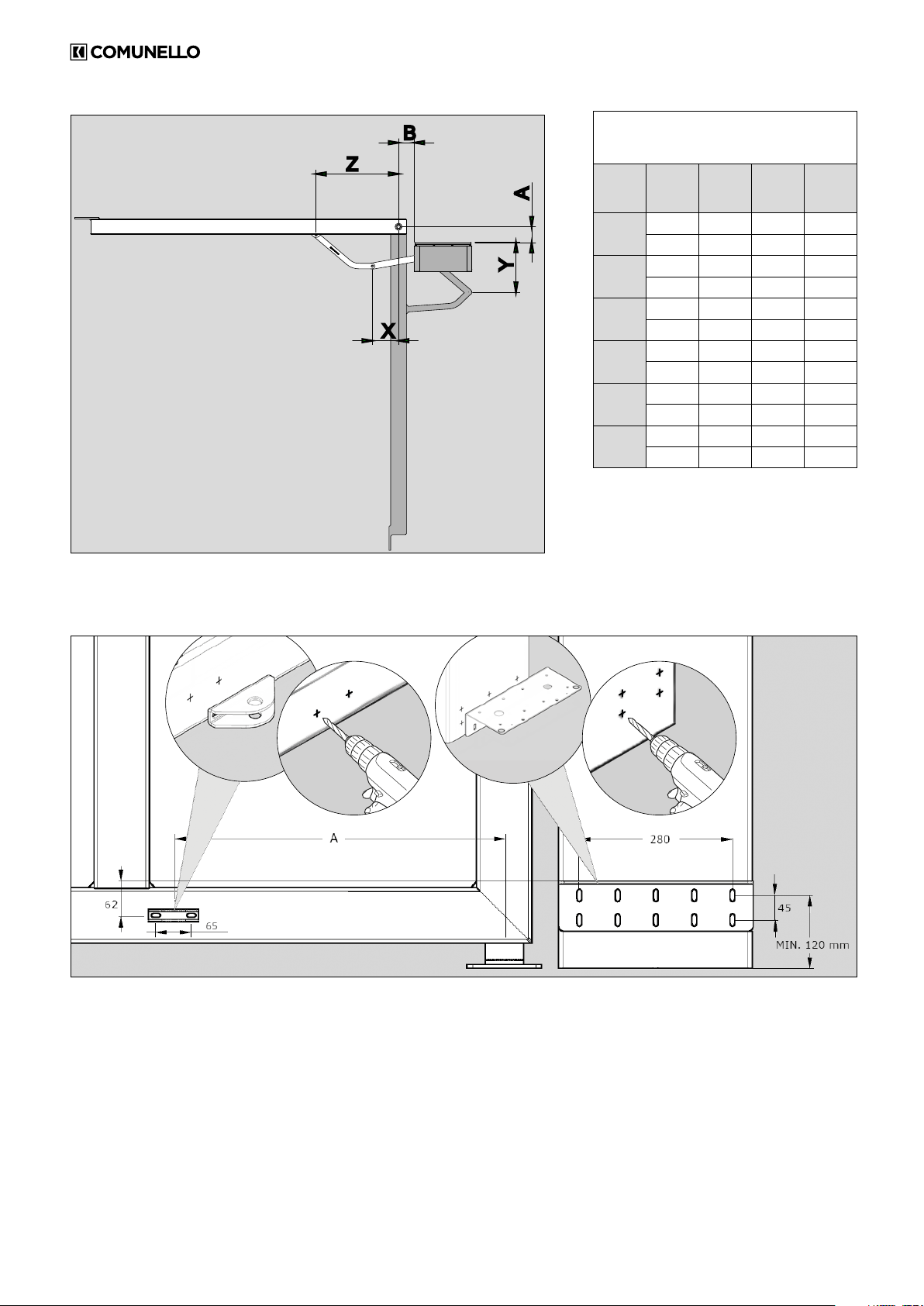
Descrizione Automazione elettromeccanica per cancelli a battente con braccetti articolati (Grandi pilastri)
Modello CONDOR 500 / ONE
è conforme alle disposizioni legislative che traspongono le seguenti direttive:
• 2014/30/EU (Direttiva EMCD)
• 2014/35/EU (Direttiva LVD)
• 2011/65/EU (Direttiva RoHS)
e che sono state applicate tutte le norme e/o speciche tecniche di seguito indicate
EN61000-6-2:2005
EN61000-6-3:2011
EN60335-1 :2012
EN60335-2-103:2015
ed emendamenti successivi
Rosà (VI) – Italia
01-12-2016
Inoltre dichiara che non è consentito mettere in servizio il macchinario no a che la macchina in cui sarà incorporata o di cui diverrà
componente sia stata identicata e ne sia stata dichiarata la conformità alle condizioni della Direttiva 2006/42/CE e alla legislazione
nazionale che la traspone.
Dr. LUCA COMUNELLO
Legale rappresentante della FRATELLI COMUNELLO s.p.a.
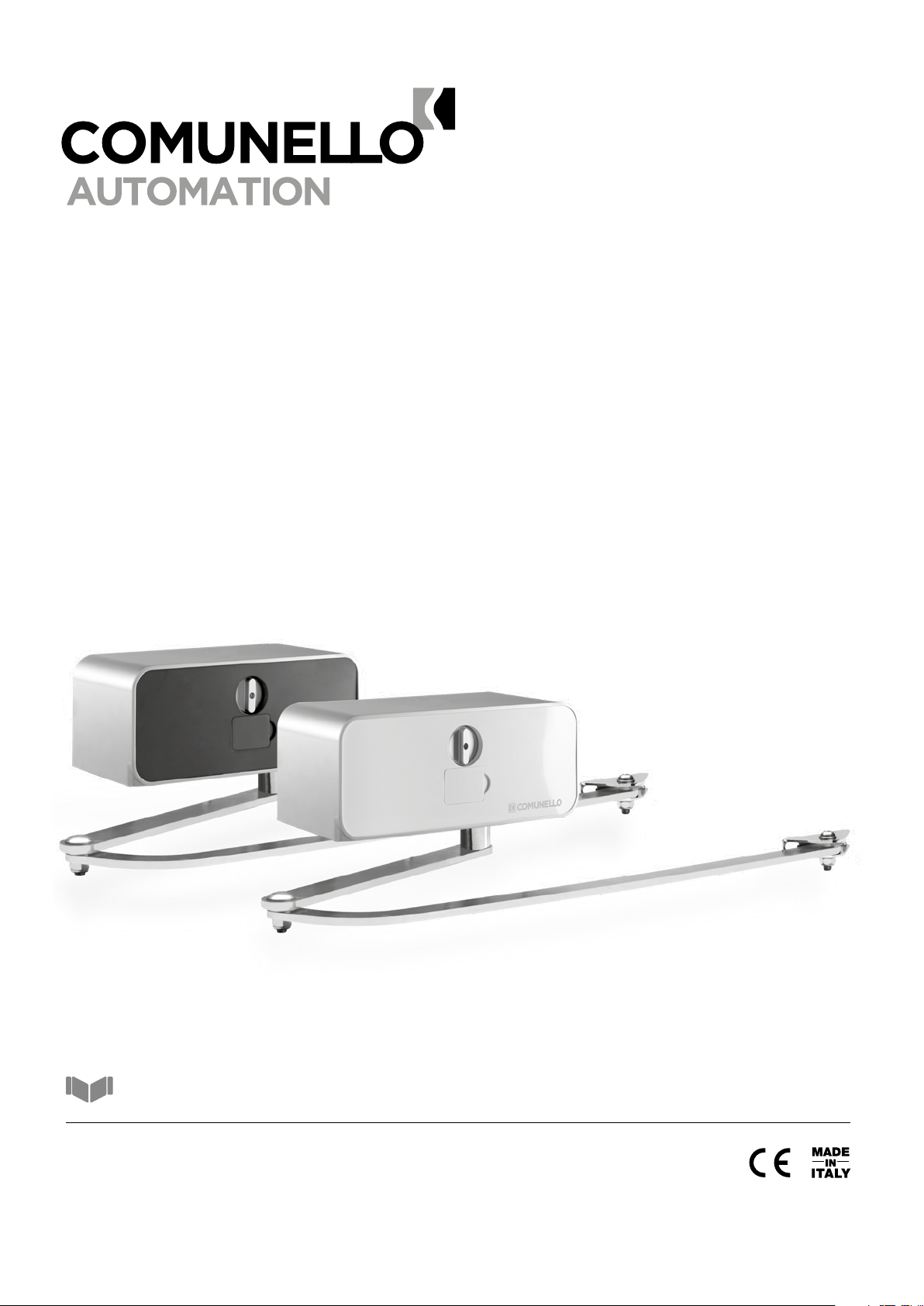
CONDOR 500
ISTRUZIONI D’USO E DI INSTALLAZIONE

11
COMUNELLO ®Copyright 2017 - All rights reserved
ITALIANO
INDICE
1 AVVERTENZE GENERALI
1.1 Avvertenze per la sicurezza
1.2 Avvertenze per l’installazione
1.3 Avvertenze per l’uso
2 DESCRIZIONE DEL PRODOTTO E DESTINAZIONE D’USO
2.1 Descrizione
2.2 Installazione tipica
3 CARATTERISTICHE TECNICHE DEL PRODOTTO
4 INSTALLAZIONE
4.1 Veriche preliminari
4.2 Limiti d’impiego
4.3 Installazione
4.3.1 Installazione
4.3.2 Installazione necorsa
4.3.3 Sblocco manuale del motoriduttore
5 PREDISPOSIZIONE AI COLLEGAMENTI ELETTRICI
6 COLLAUDO
7 MANUTENZIONE DEL PRODOTTO
8 RICAMBI
9 SMALTIMENTO DEL PRODOTTO
10 GARANZIA
1 AVVERTENZE
1.1 AVVERTENZE PER LA SICUREZZA
Il presente manuale di installazione è rivolto
esclusivamente a personale professionalmente
competente. È necessario leggere tutte le
istruzioni prima di procedere all’installazione.
Tutto quello che non è espressamente previsto in
queste istruzioni non è permesso; usi non previsti
potrebbero essere fonte di danni al prodotto e
mettere in pericolo persone e cose. Il costruttore
declina qualsiasi responsabilità dall’inosservanza
della buona tecnica nella costruzione dei cancelli,
nonché delle deformazioni che potrebbero
vericarsi durante l’uso. Conservare questo
manuale anche per utilizzi futuri. La progettazione,
la fabbricazione dei dispositivi che compongono
CONDOR 500 ed il presente manuale rispettano
pienamente la norma vigente. Considerando le
situazioni di rischio che possono vericarsi durante
l’installazione e l’uso di CONDOR 500 è necessario
che anche l’installazione avvenga nel pieno rispetto
di leggi, norme e regolamenti; in particolare:
1.2 AVVERTENZE PER L’INSTALLAZIONE
• Prima di iniziare l’installazione vericare la
necessità di ulteriori dispositivi e materiali che
possono servire a completare l’automazione con
CONDOR 500 in base alla specica situazione
d’impiego.
• L’automatismo non deve essere utilizzato
prima di aver messo in sicurezza il cancello.
• Il materiale dell’imballaggio deve essere smaltito
nel pieno rispetto della normativa locale.
1.3 AVVERTENZE PER L’USO
• Non eseguire modiche su nessuna parte
se non previste nel presente manuale.
Operazioni di questo tipo possono solo causare
malfunzionamento. Il costruttore declina ogni
responsabilità per danni derivati da prodotti
modicati.
• Evitare che le parti dell’automatismo possano
venir immerse in acqua o in altre sostanze
liquide. Anche durante l’installazione evitare
che liquidi possano penetrare all’interno della
centrale e di altri dispositivi aperti.
• Qualora sostanze liquide siano penetrate
all’interno dei dispositivi dell’automatismo,
scollegare immediatamente l’alimentazione
elettrica e rivolgersi al servizio di assistenza; l’uso
di CONDOR 500 in tali situazioni può causare
situazioni di pericolo.
• Non tenere qualsiasi componente di CONDOR
vicino a fonti di calore né esporlo a amme; tali
azioni possono danneggiarlo ed essere causa
di malfunzionamenti, incendio o situazioni di
pericolo.
• Nel caso di lunghi periodi di inutilizzo, per
evitare il rischio di perdite di sostanze nocive
dalla batteria opzionale è preferibile estrarla e
custodirla in luogo asciutto.
• Collegare la centrale solo ad una linea di
alimentazione elettrica dotata di messa a terra di
sicurezza.
• Tutte le operazioni che richiedono l’apertura
dei gusci di CONDOR 500 devono avvenire
con la centrale di comando scollegata
dall’alimentazione elettrica; se il dispositivo di
sconnessione non è a vista apporvi un cartello:
“ATTENZIONE MANUTENZIONE IN CORSO”.
• Qualora si verichino interventi di interruttori
automatici o di fusibili, prima di ripristinarli è
necessario individuare ed eliminare il guasto.
• Nel caso di guasto non risolvibile facendo
uso delle informazioni riportate nel presente
manuale, interpellare il servizio di assistenza.
2 DESCRIZIONE DEL PRODOTTO E
DESTINAZIONE D’USO
2.1 DESCRIZIONE DEL PRODOTTO
Attuatore elettromeccanico a braccetto articolato è adatto ad ante singole
no a 5 metri. Costituito da una scocca di ingombro ridotto in alluminio e
braccio in acciaio.
E
C
F
B B
G
C
F
A A
D
2.2 INSTALLAZIONE TIPICA
A CONDOR 500
B FOTOCELLULE IN APERTURA
C FOTOCELLULE IN CHIUSURA
D LAMPEGGIANTE
E SELETTORE A CHIAVE
F ARRESTO FINECORSA IN APERTURA
G CENTRALINA ESTERNA

12 COMUNELLO ®Copyright 2017 - All rights reserved
3 CARATTERISTICHE TECNICHE DEL
PRODOTTO
CONDOR 500
Alimentazione motore 24V
ONE 24V
230V ~50 Hz
Potenza assorbita 150 W 280 W
Assorbimento 6,5 A 1,2 A
Coppia 330 Nm 440 Nm
Intermittenza di lavoro uso intensivo 40%
Grado di protezione IP 24 D
Classe di isolamento II 1 messa a terra
Temp. di funzionamento da -20°C a + 50°C
Velocità 0,15 rad/sec 0,1 rad/sec
Peso 8,8 Kg 11,3 Kg
LIMITS OF USE
0 100 200 300 400
500
3.25
3.5
3.75
4
4.5
4.75
5
LEAF WEIGHT (Kg)
LEAF LENGHT (m)
AC-100
A B X Y Z
50
50 380 331 600
100 487 253 550
100
50 409 297 593
100 498 230 543
150
50 426 272 281
100 504 216 531
200
50 440 247 566
100 509 201 516
250
50 447 231 520
100 509 200 497
300
50 455 213 520
100 422 339 470
4 INSTALLAZIONE
4.1 VERIFICHE PRELIMINARI
Prima di procedere all’installazione, è necessario verificare l’integrità
dei componenti del prodotto, l’adeguatezza del modello scelto e
l’idoneità dell’ambiente destinato all’installazione:
• Verificare che tutto il materiale da utilizzare sia in ottimo stato e
adatto all’uso previsto.
• Verificare che la struttura meccanica del cancello sia adatta ad
essere automatizzata. Il presente prodotto non può automatizzare
un cancello che non sia già efficiente e sicuro; inoltre, non può
risolvere difetti causati da un’installazione errata del cancello o da
una sua cattiva manutenzione.
• Verificare che le condizioni di funzionamento dei dispositivi siano
compatibili con i limiti d’impiego dichiarati.
• Muovere manualmente le ante del cancello nelle due direzioni e
accertarsi che lo sforzo sia costante.
• Portare manualmente le ante del cancello in una posizione qualsiasi;
quindi lasciarle ferme e accertarsi che non si muovano da sole.
• Verificare che la zona di fissaggio del motoriduttore sia compatibile
con l’ingombro di quest’ultimo ed accertarsi che ci sia lo spazio
sufficiente per la rotazione completa del suo braccio.
• Accertarsi che ci sia spazio sufficiente per la manovra manuale di
sblocco del motoriduttore.
• Accertarsi che le superfici scelte per installare i vari dispositivi,
siano solide e possano garantire un fissaggio stabile.
• Accertarsi che ciascun dispositivo da installare sia collocato in una
posizione protetta e al riparo da urti accidentali.
4.2 LIMITI D’IMPIEGO
Prima di eseguire l’installazione, verificare che il motore sia
correttamente dimensionato al peso ed alla lunghezza delle ante e sia
nei limiti dei valori riportati nel capitolo 3 “Caratteristiche tecniche del
prodotto”.
Per consentire l’installazione del motoriduttore, la larghezza minima del
pilastro deve essere di 370 mm. Il braccio del motore deve essere
fissato all’anta in una zona robusta (ad esempio sul telaio).
4.3 INSTALLAZIONE
4.3.1 INSTALLAZIONE
Prendendo come riferimento la FIG. 1, (con l’aiuto della tabella) misurata
la quota A trovare la quota indicativa B.
• Vericare di avere gli spazi di manovra necessari al braccio per
completare il movimento di apertura (quota C) (FIG. 1).
• Facendo riferimento alla FIG. 2, praticare 4 fori di diametro adeguato al
tipo di tasselli utilizzati per il ssaggio della piastra 1.
• Rispettate la quota minima 120 mm indicata per evitare di installare il
motoriduttore troppo vicino al suolo (FIG. 2).
• Fissare la piastra supporto motore ad “L”.
• Praticare 2 fori per il ssaggio della staffa snodo, rispettando il valore
della quota B (FIG. 1) e l’allineamento (quota 62 mm) alla staffa
motoriduttore indicato in FIG. 2.
• Fissare la piastra a snodo.
• Qualora le zone di ssaggio fossero di spessore esiguo o comunque
deboli, provvedere a rinforzare tali zone.
•
Portare l’anta del cancello nella posizione di massima chiusura (FIG. 3).
• Slare il carter del motore (viene fornito libero senza viti di ssaggio)
(FIG. 4).
• Fissare il motoriduttore alla staffa con le quattro viti e dadi in dotazione.
Nella gura il motore è installato per un’anta Destra (FIG. 5A). Nel caso
di anta sinistra ruotare il motore di 180° (FIG. 5B).
• Assemblare il braccio 1 al braccio 2 come illustrato in FIG.6A per ante
destre e FIG. 6B per ante sinistre.
• Fissare i bracci all’albero motore come illustrato in FIG. 7.
• Fissare il braccio alla staffa snodo, utilizzando boccola, rondella,
bullone e dado (FIG. 8).
• Controllare che la staffa e il braccio siano perfettamente in bolla.
• Regolare il necorsa come illustrato nel paragrafo 4.4.2.
4.3.2 INSTALLAZIONE FINECORSA
Se il carter è installato, toglierlo come illustrato nella FIG. 4.
• Portare l’anta in completa chiusura (FIG.10).
•
Ruotare la camma inferiore no a far scattare lo switch inferiore (FIG. 10).
• Stringere la canna avvitando la vite.
• Portare l’anta in completa apertura (FIG. 11).
•
Ruotare la camma superiore no a far scattare lo switch superiore (FIG. 12).
• Stringere la canna avvitando la vite.
• Collegare gli switch alla scheda elettronica posta sulla parte superiore
del motore come spiegato nel capitolo 5 “PREDISPOSIZIONE AI
COLLEGAMENTI ELETTRICI”.
• Assemblare il carter e la leva di sblocco come illustrato in FIG. 14.
4.3.3 SBLOCCO MANUALE DEL MOTORE
Lo sblocco manuale va attivato quando si deve aprire manualmente
il cancello. L’attivazione del sistema di sblocco potrebbe provocare
movimenti incontrollati del cancello nel caso in cui siano presenti
sbilanciamenti o guasti meccanici.
• Aprire lo sportellino frontale ed inserire la chiave in dotazione (FIG. 15).
• Ruotare la chiave in senso orario per 90°. Impugnare la maniglia
di sblocco, spingerla e ruotarla in senso orario no al suo arresto
(FIG.16A - 16B). In questo modo si rende folle il pignone permettendo
così, l’apertura manuale del cancello. Nel caso il motore avesse
l’orientamento SX, ruotare la chiave in senso orario per 90°. Impugnare

13
COMUNELLO ®Copyright 2017 - All rights reserved
ITALIANO
la maniglia di sblocco, spingerla e ruotarla in senso antiorario no al
suo arresto.
• Non spingere violentemente l’anta del cancello, ma accompagnarla
per tutta la sua corsa (FIG. 17).
• La chiave non si può togliere dalla serratura no a quando la maniglia
non viene portata nella posizione iniziale.
• Per ripristinare il comando motorizzato, portare prima la maniglia
e poi la chiave nella posizione iniziale di chiusura (FIG. 18A - 18B),
quindi togliere la chiave e riporla in un luogo sicuro e conosciuto agli
interessati (FIG. 19).
5 PREDISPOSIZIONE AI COLLEGAMENTI
ELETTRICI
ATTENZIONE! Per il collegamento alla rete, utilizzare cavo multipolare
previsto da normativa vigente come da manuale della centrale.
• Effettuare lo sblocco manuale come illustrato nel paragrafo 4.4.3.
• Slare il carter del motore verso l’alto.
• Collegare il lo giallo/verde (messa a terra) al capocorda ad occhiello
come illustrato in FIG. 20.(per i modelli di classe I).
• Portare i li elettrici alla scheda elettronica posta nella parte superiore
del motore (FIG. 21).
6 COLLAUDO
Ogni singolo elemento dell’automatismo, ad esempio bordi sensibili,
fotocellule, arresto di emergenza, ecc. richiede una specica fase di
collaudo; per questi dispositivi si dovranno eseguire le procedure riportate
nei rispettivi manuali istruzioni. Per il collaudo di CONDOR 500 eseguire la
seguente sequenza di operazioni:
• Vericare che sia stato rispettato rigorosamente tutto quanto previsto
nel presente manuale ed in particolare nel capitolo 1 “Avvertenze”.
• Utilizzando i dispositivi di comando o arresto previsti (selettore a
chiave, pulsanti di comando o trasmettitori radio), effettuare delle
prove di apertura, chiusura ed arresto del cancello e vericare che il
comportamento corrisponda a quanto previsto.
• Vericare uno ad uno il corretto funzionamento di tutti i dispositivi di
sicurezza presenti nell’impianto (fotocellule, bordi sensibili, arresto di
emergenza, ecc.).
• Se le situazioni pericolose provocate dal movimento dell’anta sono
state salvaguardate mediante la limitazione della forza d’impatto si
deve eseguire la misura della forza secondo quanto previsto dalla
norma EN 12445.
7 MANUTENZIONE DEL PRODOTTO
La manutenzione deve essere effettuata regolarmente da parte di personale
qualicato secondo quanto previsto dalle leggi e normative vigenti. Per
CONDOR 500 è necessaria una manutenzione programmata al massimo
entro 6 mesi o 10.000 manovre dalla precedente manutenzione.
• Scollegare qualsiasi fonte di alimentazione dal motore.
• Vericare e sostituire tutte le parti di movimento usurate.
• Vericare lo stato di deterioramento di tutte le parti dell’automazione.
8 RICAMBI
È possibile acquistare dei particolari di ricambio, in caso di tale necessità
contattare l’assistenza tecnica.
9 SMALTIMENTO
Al termine della vita dell’automazione, assicuratevi che lo smantellamento
sia eseguito da personale qualicato e che i materiali vengano riciclati o
smaltiti secondo le norme valide a livello locale.
10GARANZIA
a) La presente garanzia nei rapporti commerciali o in caso di vendita
di beni per uso professionale è limitata alla riparazione o sostituzione
del pezzo del Prodotto riconosciuto da FRATELLI COMUNELLO SPA
quale difettoso mediante Prodotti rigenerati equivalenti (di seguito
“Garanzia Convenzionale”), non risulta compresa nella garanzia il costo
necessario per le attività di riparazione e sostituzione del materiale (a titolo
esemplicativo costi di manodopera, noleggio materiali, etc).
b) È esclusa l’applicazione della disciplina dettata dagli articoli 1490-1495
del Codice Civile.
c) FRATELLI COMUNELLO SPA garantisce il funzionamento dei Prodotti
nei limiti indicati al superiore punto sub 1. Salvo diverso accordo, la
validità della Garanzia Convenzionale è di 24 (ventiquattro) mesi dalla
data di produzione, rilevabile sui Prodotti. La Garanzia risulterà efcace
e vincolante per COMUNELLO solo se il prodotto verrà correttamente
montato e manutentato in conformità alle regole di installazione e di
sicurezza indicate nella documentazione fornita da COMUNELLO o
comunque rinvenibile sul sito http://www.comunello.com/it/corporate/
condizioni-generali/
d) La garanzia non comprende: avarie o danni causati dal trasporto; avarie
o danni causati da vizi dell’impianto elettrico presente presso l’acquirente
il prodotto e/o da trascuratezza, negligenza, inadeguatezza, uso anomalo
di tale impianto; avarie o danni dovuti a manomissioni poste in essere
da parte di personale non autorizzato o conseguenti allo scorretto uso/
installazione (a questo proposito, si consiglia una manutenzione del
sistema almeno ogni sei mesi) o all’impiego di pezzi di ricambio non
originali; difetti causati da agenti chimici e/o fenomeni atmosferici.
La garanzia non comprende il costo per materiale di consumo, in ogni
caso COMUNELLO matura il credito per l’intervento eseguito presso il
cliente, laddove quest’ultimo si riveli inutile poiché non risultava operante
la garanzia o perché il cliente aveva utilizzato il prodotto COMUNELLO in
modo negligente, imprudente od imperito, tale per cui il corretto utilizzo
del prodotto avrebbe potuto evitare l’installazione.
e) Termini attuativi: salvo diverso accordo, il diritto alla Garanzia
Convenzionale si esercita esibendo copia del documento di acquisto
(fattura scale) a COMUNELLO. Il Cliente deve denunciare il difetto a
COMUNELLO entro il termine di decadenza di 30 (trenta) giorni dalla
scoperta.
L’azione deve essere esercitata entro il termine di prescrizione di 6
(sei) mesi dalla scoperta. I pezzi dei Prodotti per i quali viene richiesta
l’attivazione della Garanzia Convenzionale devono essere spediti dal
Cliente presso FRATELLI COMUNELLO SPA, Via Cassola 64, 36027
Rosà (VI) Italia.
“
f) Il Cliente non potrà richiedere il risarcimento di danni indiretti, mancati
protti, perdita di produzione ed in ogni caso non potrà pretendere a titolo
di risarcimento somme superiori al valore dei componenti o dei Prodotti
forniti. Tutte le spese per il trasporto dei Prodotti da riparare o riparati,
anche se coperti dalla Garanzia Convenzionale, sono a carico del Cliente.
g) Nessun intervento esterno effettuato dal personale tecnico di
COMUNELLO è coperto dalla Garanzia Convenzionale.
h) Modiche speciche delle condizioni della Garanzia Convenzionale
qui descritte possono essere denite dalle parti nei propri contratti
commerciali.
i) In caso di controversia legale di qualsiasi natura è applicabile il diritto
italiano ed è competente il Foro di Vicenza.

14 COMUNELLO ®Copyright 2017 - All rights reserved
Fratelli Comunello S.p.A.
Company with certied Quality Management System
UNI EN ISO 9001:2015.
CONDOR 500
INSTALLATION AND USER’S MANUAL
EC DECLARATION OF COMFORMITY:
The undersigned Mr. Luca Comunello, representing the following manufacturer,
Fratelli COMUNELLO Spa
Via Cassola 64, 36027 Rosà (VI) – Italy
DECLARES that the equipment described below:
Description: Swing gates automation with articulated arms (Great pillars)
Model: CONDOR 500 / ONE
Is in compliance with the provisions set down in the following directives:
• 2014/30/EU (Directive EMCD)
• 2014/35/EU (Directive LVD)
• 2011 /65/EU (Directive RoHS)
and that all the rules and/or technical specications shown below have been applied:
EN61000-6-2:2005
EN61000-6-3:2011
EN60335-1 :2012
EN60335-2-103:2015
and the following amendments.
Rosà (VI) – Italia
01-12-2016
and he also declares that it is not allowed to commission the device until the machinery where it will be incorporated or whose it will
become a component will have been identied and will have been declared in compliance with the conditions of the 2006/42 EC Directive
and with the national legislation that transpose it.
Mr. Luca Comunello
Fratelli Comunello Legal Representative

15
COMUNELLO ®Copyright 2017 - All rights reserved
ENGLISH
CONTENTS
1 GENERAL PRESCRIPTIONS
1.1 Safety prescriptions
1.2 Installation prescriptions
1.3 Operating prescriptions
2 MODELS AND PRODUCTS DESCRIPTION
2.1 Description
2.2 Typical installation
3 PRODUCT TECHNICAL SPECIFICATIONS
4 INSTALLATION
4.1 Preliminary checks
4.2 Operating limits
4.3 Installing the CONDOR operator
4.3.1 Installation
4.3.2 Installation of limit stops and switches
4.3.3 Operator manual release
5 PREPARATION FOR ELECTRICAL CONNECTIONS
6 TESTING
7 PRODUCT MAINTENANCE
8 SPARE PARTS
9 DISPOSAL OF THE PRODUCT
10 WARRANTY
1 PRESCRIPTIONS
1.1 SAFETY PRESCRIPTIONS
This installation manual is addressed exclusively
to professionally skilled personnel. Read all the
instructions carefully before starting the installation
procedures. Any operations that are not expressly
set down in these instructions are to be considered
prohibited; improper use may result in damage to
the product and place persons and property at risk.
The manufacturer declines all liability for failure to
observe best practices in gate construction and
for any possible deformation that may occur during
use of the product. Store this manual in a safe place
for future reference. The design and construction
of the devices of which model CONDOR 500 is
composed and this manual are in full compliance
with statutory legislation.
In consideration of potential hazards that may arise
during the installation and use of CONDOR 500,
the installation procedures must be carried out in
full compliance with the applicable laws, standards
and regulations; namely:
1.2 INSTALLATION PRESCRIPTIONS
• Before starting the installation procedures make
sure you have any additional devices and materials
that may be required to complete the automation
system with CONDOR 500 in consideration of the
specic application.
• The automation system must not be used until the
gate has been made safe.
• Dispose of packaging materials in compliance
with local regulations.
1.3 OPERATING PRESCRIPTIONS
• No modications can be made to any part of
the product unless specied in this manual.
Unauthorized modication of the product is
likely to lead to malfunctions. The manufacturer
declines any liability for damage caused by
unauthorized modications.
• The parts of the automation system must never
be immersed in water or other liquids. During
the installation procedures ensure that no liquids
penetrate inside the control unit or other open
devices.
• If liquids penetrate any parts of the automation
system disconnect the electrical power supply
immediately and consult the technical service;
the use of CONDOR 500 in such conditions
may give rise to potentially hazardous situations.
• Keep all parts CONDOR 500 away from heat
sources and open ames; exposure to heat or
ames may damage the devices and cause
faults, re, or hazardous situations.
• When the equipment remains unused for a long
time, remove the optional battery and store it
in a dry place to avoid the risk of leakage of
harmful substances.
• Connect the control unit exclusively to an electric
power supply line equipped with an efcient
protective earth conductor.
• Any operations that require the housing of
CONDOR 500 to be opened must be performed
with the control unit and the electrical power
supply disconnected; if the disconnect device
is not clearly visible from where you are working,
attach a warning notice to the effect: “WARNING
- MAINTENANCE IN PROGRESS”.
• In the case of tripping of circuit breakers or
blowing of fuses, nd the fault and remedy it
before resetting the circuit breaker or changing
the fuse.
• If the fault cannot be remedied using the
information given in this manual, consult the
technical service.
2 PRODUCT DESCRIPTION AND INTENDED USE
2.1 PRODUCT DESCRIPTION
Electromechanical articulated arm operator designed for mounting on deep
pillars and for single leaves up to 5 metres. Composed of an aluminium
housing and steel arm.
2.2 TYPICAL INSTALLATION
E
C
F
B B
G
C
F
A A
D
KEY
A CONDOR 500
B OPENING PHOTOCELLS
C CLOSING PHOTOCELLS
D FLASHING LIGHT
E KEY SELECTOR SWITCH
F LIMIT STOP
G EXTERNAL CONTROL UNIT

16 COMUNELLO ®Copyright 2017 - All rights reserved
3 PRODUCT TECHNICAL SPECIFICATIONS
CONDOR 500
Operator power supply 24V
ONE 24V
230V ~50 Hz
Power consumption 150 W 280 W
Current input 6,5 A 1,2 A
Torque 330 Nm 440 Nm
Duty cycle intensive 40%
Protection rating IP 24 D
Insulation class II 1 (earthing)
Working temperature from -20°C to + 50°C
Speed 0,15 rad/sec 0,1 rad/sec
Weight 8,8 Kg 11,3 Kg
LIMITS OF USE
0 100 200 300 400
500
3.25
3.5
3.75
4
4.5
4.75
5
LEAF WEIGHT (Kg)
LEAF LENGHT (m)
AC-100
A B X Y Z
50
50 380 331 600
100 487 253 550
100
50 409 297 593
100 498 230 543
150
50 426 272 281
100 504 216 531
200
50 440 247 566
100 509 201 516
250
50 447 231 520
100 509 200 497
300
50 455 213 520
100 422 339 470
4 INSTALLATION
4.1 PRELIMINARY CHECKS
Before starting the installation work, check the condition of the product
components, the suitability of the chosen gate opener model and the
suitability of the intended installation environment:
• Ensure that all material used is in perfect condition and t for purpose.
• Make sure that the mechanical structure of the gate is suitable for
automation. This product cannot be used to automate a gate unless the
gate is already in good working order and safe and it cannot remedy
defects caused by incorrect installation or lack of maintenance of the gate.
• Check the stated operating limits.
• Move the gate leaves manually in both directions to ensure the force
required is constant throughout the full range of movement.
• Move the gate leaves manually to any position then release them to
check that they remain stationary.
• Check that the area in which the operator is to be mounted is compatible
with the size of the unit and make sure there is sufcient clearance for
the full movement of the arm.
• Ensure that there is sufcient space around the operator to perform the
manual release procedure.
• Ensure that the surfaces on which the devices are to be mounted are
solid and able to provide a secure anchorage.
• Ensure that all devices to be installed are in a protected location and
such as to minimize the risk of accidental impact.
4.2 OPERATING LIMITS
Before starting the installation work, make sure the operator is correctly sized
in relation to the dimensions and length of the gate leaves and within the
limits of the values given in the chapter “Product technical specications”:
For installation purposes, the minimum width of the gate pillar is 370 mm.
The operator arm must be secured to the gate leaf in a sufciently robust
position (e.g. on the gate frame).
4.3 INSTALLATION
4.3.1 INSTALLATION
With reference to FIG. 1, (with the aid of the table) measure dimension “A”
and nd guideline dimension “B”:
• Check that the arm has sufcient operating clearance to complete the
opening movements (dimension C). (FIG. 1).
• Referring to FIG. 2, drill 4 holes of suitable diameter in relation to the type
of anchor bolts used to x plate I.
• Comply with the minimum dimension of 120 mm required to avoid
installing the operator too close to the ground (FIG. 2).
• Secure the “L” shaped operator support plate.
• Drill two holes for xing the articulated arm, complying with the value of
dimension B shown in FIG. 1 and ensuring alignment (dimension 62
mm) with the operator bracket shown in (FIG. 2).
• Secure the plate to the articulation.
• If the areas of xing are too insubstantial or insufciently sturdy, they
must be reinforced.
• Bring the gate leaf to the fully closed position (FIG. 3).
• Remove the operator cover (the cover is supplied loose, without xing
screws) (FIG. 4).
• Secure the operator to the bracket with the nuts and bolts supplied; .
The gure shows the operator installed for a right-hand (FIG.5A) leaf. For
a left-hand leaf rotate the operator through 180° (FIG.5B).
• Assemble arm 1 to arm 2 as shown in FIG. 6A, for a right-hand leaf, and
in 6B for a left-hand leaf (AC 102 - 103 -104).
• Secure the arms to the drive shaft as shown in FIG. 7.
• Fix the arm to the articulated bracket using bushing, washer, nut and
bolt (FIG. 8).
• Check that the bracket and arm are perfectly level.
• Adjust the limit stop as described in heading 4.4.2.
4.3.2 INSTALLATION OF LIMIT SWITCHES
If the cover is tted, remove it as shown in FIG. 4
• Bring the gate leaf to its fully closed position (FIG.10).
• Rotate the lower cam until causing the lower switch to trip (FIG. 10).
• Lock the cam by tightening the screw.
• Bring the gate leaf to its fully open position (FIG. 11).
• Rotate the upper cam until causing the upper switch to trip (FIG. 12).
• Lock the cam by tightening the screw.
• Connect the limit switches to the electronic board located at the top of
the operator, as described in chapter 5 “ELECTRICAL CONNECTIONS”.
• Assemble the housing and release lever as shown in FIG. 14.
4.4.3 OPERATOR MANUAL RELEASE
Perform the manual release procedure when the gate is to be opened
manually. Activation of the release system may result in uncontrolled
movements of the gate in the presence of imbalance or mechanical faults.
• Open the front hatch and insert the supplied key (FIG. 15).
• Turn the key by 90 degrees clockwise. Hold the release lever, push
it and turn it clockwise until it stops (FIG.16A-16B). This action serves
to disengage the operator pinion thereby allowing the gate to be
opened manually. If the motor has the LEFT orientation, turn the key
by 90 degrees clockwise. Hold the release handle, push it and turn it
anticlockwise until it stops.
• Do not swing the gate leaf with force but rather accompany it through its
full movement (FIG. 17).
• The key cannot be removed from the lock until the release handle is
returned to its initial position.
• To resume motorized control of the gate, bring the release handle to its
initial locked position (FIG. 18A-18B), then remove the key and stow it
in a safe place that is known only to persons authorized to use the gate
(FIG. 19).

17
COMUNELLO ®Copyright 2017 - All rights reserved
ENGLISH
5 PREPARATION FOR ELECTRICAL
CONNECTIONS
WARNING! To connect to the network, use a multipolar cable provided by
regulations by the book’s unit.
• Perform the manual release as illustrated in heading 4.4.3.
• Remove the operator cover upwards.
• Connect the yellow/green wire (earth) to the terminal eye as shown in
the gure (FIG. 20) (for models of class I).
• Route the wires to the electronic board located at the top of the operator
(FIG. 21).
6 TESTING
Each part of the automation system, e.g. safety edges, photocells,
emergency stop, etc. must be tested; follow the procedures shown in
the instruction manuals supplied with the devices in question. Perform the
following sequence of operations for testing of CONDOR 500:
• Check that all the prescriptions in this manual have been followed
scrupulously, with special attention to the matters set down in
chapter 1 “PRESCRIPTIONS”.
• Using the supplied control or stopping devices (key selector switch,
pushbuttons or radio transmitters), perform gate opening, closing
and stopping tests and make sure the gate responds correctly to the
various commands.
• Check operation of all the system’s safety devices (photocells, safety
edges, emergency stop, etc.), one by one.
• If potentially hazardous situations caused by movement of the gate leaf
have been eliminated by limitation of impact force, the associated force
must be measured as prescribed in standard EN 12445.
7 PRODUCT MAINTENANCE
Maintenance must be carried out at regular intervals by qualied personnel
in compliance with the provisions of statutory legislation and the regulations
in force. CONDOR 500 must be serviced at least once every 6 months or
after 10.000 operating cycles since the last service:
• Disconnect the operator from all power supplies
• Check all the moving parts and replace any worn parts
• Check all parts of the automation system for signs of deterioration
8 SPARE PARTS
Spare parts can be purchased by contacting the technical service.
9 DISPOSAL
At the end of its useful life the automation system must be dismantled by
qualied personnel and the materials must be recycled or disposed of in
compliance with the local legislation in force.
10WARRANTY
a) In business relationships or in case of products sold for professional
use, this warranty is limited to the repair or replacement of product parts
that FRATELLI COMUNELLO SPA acknowledges as defective, through
equivalent re-manufactured Products (the “Conventional Warranty”); the
warranty does not include the costs necessary for repairing or replacing the
material (e.g. labour costs, rental of equipment etc).
b) The provisions contained in articles 1490 to 1495 of the Italian Civil Code
shall not apply.
c) FRATELLI COMUNELLO SPA warrants the proper operation of the
products within the limits indicated in 1 above. Unless otherwise agreed,
the validity of the Conventional Warranty is 24 (twenty-four) months from
the production date, which can be found on the products. The Warranty
shall be effective and binding on COMUNELLO only if the product has
been correctly installed and maintained in accordance with the installation
and safety rules set out in the documentation provided by COMUNELLO or
otherwise available on the website http://www.comunello.com/corporate/
general_conditions_sales/
d) The warranty does not cover: failures or damage caused by transport;
failures or damage caused by defects in the electrical system of the buyer
and/or by carelessness, negligence, inadequate or abnormal use of such
system; failure or damage due to tampering carried out by unauthorized
personnel or due to incorrect use / installation (in this regard, system
maintenance at least every six months is recommended) or the use of
non-original spare parts; defects caused by chemical agents and/or
atmospheric phenomena.
The warranty does not cover the cost of consumables; in any event,
COMUNELLO shall be entitled to a consideration for the work performed
at the Customer, where such work proves useless as the warranty did not
apply or because the customer had used the Comunello product in a
negligent, reckless or incompetent manner, such that the proper use of the
product could have avoided the work.
e) Implementation terms: unless otherwise agreed, the right to the
Conventional Warranty is exercised by showing a copy of the purchase
document (invoice) to COMUNELLO. Any defect must be notied to
COMUNELLO within the time limit of thirty (30) days from detection of the
defect.
The action must be exercised within the limitation period of 6 (six) months
from detection of the defect. The Product parts for which the Customer
requests application of the Conventional Warranty must be returned by the
Customer to FRATELLI COMUNELLO SPA, Via Cassola 64, 36027 Rosà
(VI) Italy.
f) The Customer cannot claim compensation for indirect damage, loss of
prots, loss of production and in any case it cannot claim compensation for
an amount that exceeds the value of the supplied components or products.
All transport costs for Products that have been repaired or to be repaired,
although covered by the Conventional Warranty, shall be charged to the
Customer.
g) No external work carried out by Comunello technical staff is covered by
the Conventional Warranty.
h) Specic amendments to the Conventional Warranty conditions described
herein can be dened by the parties in their commercial contracts.
i) The Court of Vicenza (Italy) shall be the place of jurisdiction for any dispute
which will be settled according to the Italian laws.

18 COMUNELLO ®Copyright 2017 - All rights reserved
Fratelli Comunello S.p.A.
Unternehmen mit UNI EN ISO 9001:2015
zertizierten Qualitätssystem
CONDOR 500
INSTALLATIONS-UND GEBRAUCHSANLEITUNG
CE-KONFORMITÄTSERKLÄRUNG
Der Unterzeichner, Herr COMUNELLO LUCA, der den folgenden Hersteller vertritt:
F.lli COMUNELLO spa
Via Cassola 64, 36027 Rosà (VI) Italy
ERKLÄRT, dass die anbei beschriebene Ausrüstung:
Beschreibung Elektromechanische Automatisierung fuer Drehtore mit Gelenkarm (großen Säulen)
Modell CONDOR 500 / ONE
den Gesetzesbestimmungen entspricht, die folgende Richtlinien umsetzen:
• 2014/30/EU (Richtlinie EMCD)
• 2014/35/EU (Richtlinie LVD)
• 2011 /65/EU (Richtlinie RoHS)
und dass alle folgenden Normen und/oder technischen Spezikationen angewendet wurden:
EN61000-6-2:2005
EN61000-6-3:2011
EN60335-1 :2012
EN60335-2-103:2015
sowie ihre nachträglichen Änderungen.
Rosà (VI) – Italien
01-12-2016
Außerdem wird erklärt, dass es nicht erlaubt ist, die Automatisierung in Betrieb zu setzen, solange die Anlage, in die sie eingebaut wird
oder mit der sie zusammengebaut wird, identiziert wurde und deren Konformität mit den Erfordernissen der Richtlinie 2006/42/EG und
der entsprechenden nationalen Gesetzgebung erklärt wurde.
Dr. LUCA COMUNELLO
Rechtsvertreter der Firma FRATELLI COMUNELLO s.p.a.

19
COMUNELLO ®Copyright 2017 - All rights reserved
DEUTSCH
INHALTSVERZEICHNIS
1 ALLGEMEINE HINWEISE
1.1 Sicherheitshinweise
1.2 Installationshinweise
1.3 Gebrauchshinweise
2 MODELLE UND PRODUKTBESCHREIBUNGEN
2.1 Beschreibung
2.2 Typische Installation
3 TECHNISCHE EIGENSCHAFTEN DES PRODUKTS
4 INSTALLATION
4.1 Vorbereitende Überprüfungen
4.2 Einsatzgrenzen
4.3 Installation des Getriebemotors Mod. CONDOR 500
4.3.1 Installation
4.3.2 Installation des Endschalters
4.3.3 Manuelles Entriegeln des Getriebemotors
5 VORBEREITUNG AUF DIE ELEKTRISCHEN ANSCHLÜSSE
6 PRÜFUNG
7 INSTANDHALTUNG DES PRODUKTS
8 ERSATZTEILE
9 ENTSORGUNG DES PRODUKTS
10 GARANTIE
1 HINWEISE
1.1 SICHERHEITSHINWEISE
Dieses Installationshandbuch wendet sich
ausschließlich an professionell kompetentes
Personal. Alle Anleitungen sind vor der Installation
durchzulesen. Alle nicht ausdrücklich in dieser
Anleitung enthaltenen Vorgänge sind nicht erlaubt;
nicht bestimmungsgemäße Verwendungen
könnten Produktschäden verursachen und
Personen und Gegenstände in Gefahr versetzen.
Der Hersteller übernimmt keine Verantwortung für
die Nichteinhaltung der Regeln der Technik bei der
Fertigung der Tore, sowie für Verformungen, die
sich beim Gebrauch ereignen könnten. Dieses
Handbuch ist auch für zukünftige Benutzungen
aufzubewahren. Das Projekt, die Fertigung der
zu CONDOR 500 gehörenden Vorrichtungen und
dieses Handbuch erfüllen in vollem Ausmaß die
geltenden Vorschriften. Unter Berücksichtigung
der Risikosituationen, die sich während der
Installation und dem Gebrauch von CONDOR 500
ereignen können, muss auch die Installation unter
voller Einhaltung der Gesetze, Vorschriften und
Regeln erfolgen; insbesondere:
1.2 INSTALLATIONSHINWEISE
• Vor Beginn der Installation prüfen, ob zusätzliche
Vorrichtungen und Materialien notwendig sind,
die je nach der spezischen Verwendung
zur Komplettierung der Automatisierung mit
CONDOR 500 dienen können.
• Der automatische Antrieb darf nicht verwendet
werden, solange die Sicherheitsmaßnahmen
am Tor nicht erfasst wurden.
• Das Verpackungsmaterial ist unter voller
Einhaltung der örtlichen Vorschriften zu
entsorgen.
1.3 GEBRAUCHSHINWEISE
• Es dürfen nirgendwo Änderungen durchgeführt
werden, sofern nicht in diesem Handbuch
vorgesehen. Arbeiten dieser Art können lediglich
Betriebsstörungen verursachen. Der Hersteller
übernimmt keine Verantwortung für Schäden,
die von veränderten Produkten herführen.
• Es ist zu vermeiden, dass Teile des
Antriebssystems in Wasser oder andere üssige
Stoffe tauchen können. Auch während der
Installation ist zu vermeiden, dass Flüssigkeiten
in die Steuerung und andere offenen
Vorrichtungen eindringen können.
• Falls üssige Stoffe in die Vorrichtungen der
Automatik eingedrungen sind, ist unverzüglich
die Stromversorgung abzutrennen und der
Kundendienst von Comunello zu Rate zu ziehen;
eine Verwendung von CONDOR 500 in diesem
Zustand kann Gefahrsituationen verursachen.
• Die Bestandteile von CONDOR 500 dürfen
keinen Hitzequellen oder Flammen ausgesetzt
werden; sie könnten dadurch beschädigt
werden und Betriebsstörungen, Brände oder
Gefahrsituationen verursachen.
• Bei längerem Stillstand sollte der eventuelle
Akku entfernt und an einem trockenen Ort
aufbewahrt werden, um das Risiko des
Austretens schädlicher Stoffe zu vermeiden.
• Die Steuerung darf nur an eine Stromleitung mit
Schutzerdung angeschlossen werden.
• Vor allen Vorgängen, die eine Öffnung der
CONDOR 500-Gehäuse verlangen, muss
die Steuerung erst von der Stromversorgung
abgetrennt werden; falls die Abschaltvorrichtung
nicht sichtbar ist, ist ein Schild anzubringen:
„ACHTUNG! IM WARTUNGSZUSTAND”.
• Falls Selbstabschalter oder Sicherungen
ansprechen, ist vor ihrer Rückstellung bzw.
Instandsetzung der Defekt zu erkennen und zu
beseitigen.
• Im Falle von Defekten, die mit den in diesem
Handbuch enthaltenen Information nicht
behoben werden können, ist mit dem
Kundendienst von Kontakt aufzunehmen.
2 PRODUKTBESCHREIBUNG UND
BESTIMMUNGSZWECK
2.1 PRODUKTBESCHREIBUNG
Elektromechanischer Antrieb mit Gelenkarm, geeignet für tiefe Pfosten und
für Einzelügel bis 5 m. Bestehend aus einem kompakten Alugehäuse und
einem Stahlarm.
E
C
F
B B
G
C
F
A A
D
2.2 TYPISCHE INSTALLATION

20 COMUNELLO ®Copyright 2017 - All rights reserved
LEGENDE
A CONDOR 500
B FOTOZELLEN ÖFFNUNG
C FOTOZELLEN SCHLIESSUNG
D BLINKLEUCHTE
E SCHLÜSSELTASTER
F ENDANSCHLAG
G EXTERNE STEUERUNG
3 TECHNISCHE EIGENSCHAFTEN
CONDOR 500
Motorspeisung 24V
ONE 24V
230V ~50 Hz
Leistungsaufnahme 150 W 280 W
Aufnahme 6,5 A 1,2 A
Drehmoment 330 Nm 440 Nm
Einschaltdauer Intensiv 40%
Schutzgrad IP 24 D
Isolationsklasse II 1 (Erdung)
Betriebstemperatur von -20°C bis + 50°C
Laufzeit 0,15 rad/sec 0,1 rad/sec
Gewicht 8,8 Kg 11,3 Kg
LIMITS OF USE
0 100 200 300 400
500
3.25
3.5
3.75
4
4.5
4.75
5
LEAF WEIGHT (Kg)
LEAF LENGHT (m)
AC-100
A B X Y Z
50
50 380 331 600
100 487 253 550
100
50 409 297 593
100 498 230 543
150
50 426 272 281
100 504 216 531
200
50 440 247 566
100 509 201 516
250
50 447 231 520
100 509 200 497
300
50 455 213 520
100 422 339 470
4 INSTALLATION
4.1 VORBEREITENDE ÜBERPRÜFUNGEN
Vor der Installation ist zu prüfen, dass die Bestandteile des Produktes
einwandfrei sind, das gewählte Modell angemessen und der
Installationsbereich geeignet sind:
• Prüfen, dass das zu verwendende Material insgesamt einen
ausgezeichneten Zustand aufweist und für den bestimmungsgemäßen
Gebrauch geeignet ist.
• Prüfen, dass die mechanische Struktur des Tores für die Automatisierung
geeignet ist. Dieses Produkt kann kein Tor automatisieren, das nicht
allein schon efzient und sicher ist; außerdem kann es keine Fehler
beheben, die von einer falschen Installation des Tores oder seiner
schlechten Wartung verursacht sind.
• Die bescheinigten Einsatzgrenzen überprüfen.
• Die Torügel von Hand in beide Richtungen bewegen, um sich der
konstanten Schubkraft zu vergewissern.
• Die Torügel von Hand in egal welche Position bringen, stehen lassen
und feststellen, dass sie sich nicht von selbst bewegen.
• Prüfen, dass der Befestigungsbereich des Getriebemotors mit seinen
äußeren Abmessungen verträglich ist und sicherstellen, dass ein
ausreichender Platz für seine komplette Armdrehung vorhanden ist.
• Sicherstellen, dass ein ausreichender Platz für das manuelle
Entriegelungsmanöver des Getriebemotors vorhanden ist.
• Sicherstellen, dass die für die Installation der verschiedenen
Vorrichtungen gewählten Oberächen tragfähig sind und eine stabile
Befestigung garantieren.
• Sicherstellen, dass sich jede zu installierende Vorrichtung an einer
geschützten und vor unerwünschten Stößen sicheren Position bendet.
4.2 EINSATZGRENZEN
Vor der Installation prüfen, dass der Motor für das Gewicht und die Länge
der Flügel korrekt bemessen ist und innerhalb der Grenzwerte laut Kapitel
„Technische Eigenschaften des Produkts“ liegt. Um die Installation des
Getriebemotors zu ermöglichen, muss der Pfeiler eine Mindestbreite von
180 mm aufweisen. Der Arm des Motors ist an einer robusten Stelle des
Flügels zu befestigen (z.B. am Rahmen).
4.3 INSTALLATION
4.3.1 INSTALLATION
Gemäß ABB. 1 (mit Hilfe der Tabelle) das Maß „A“ erfassen und das
ungefähre Maß „B” bestimmen:
• Prüfen, dass die notwendigen Manöverräume für die komplette
Öffnungsbewegung des Armes (Aktie C) zur Verfügung stehen (ABB. 1).
• Gemäß ABB. 2, 4 Bohrungen mit einem angemessenem Durchmesser
für die zur Befestigung der Platte 1 zu verwendenden Dübel fertigen.
• Das angegebene Mindestmaß von 120 mm einhalten, um zu vermeiden,
dass der Getriebemotor zu nah am Boden installiert wird (ABB.2).
• Die „L“-förmige Motorhalteplatte befestigen.
• 2 Bohrungen für die Befestigung des Gelenkhaltebügels fertigen, unter
Einhaltung der Maßangabe B (ABB. 1) und der Ausrichtung (42 mm) mit
dem Getriebemotor-Haltebügel in ABB. 2.
• Die Gelenkplatte befestigen.
• Falls die Befestigungsbereiche nicht genug dick bzw. irgendwie
schwach sind, sind sie zu verstärken.
• Den Torügel in die maximale Schließposition bringen (ABB. 3).
• DasMotorgehäuseabnehmen(diesesistfreivonBefestigungsschrauben)
(ABB. 4).
• Den Getriebemotor mit den beigestellten Schrauben und Muttern am
Bügel befestigen. Die Abbildung zeigt den Motor in der Installation für
einen rechten (ABB. 5A) Flügel. Zur Installation für einen linken Flügel ist
der Motor um 180° (ABB. 5B) zu drehen.
• Für rechte Flügel gemäß ABB. 6A den Arm 1 am Arm 2 montieren und
für linke Flügel gemäß ABB. 6B (AC 102 - 103 -104).
• Die Arme gemäß ABB. 7 an der Motorwelle befestigen.
• Den Arm mit Buchse, Scheibe, Mutterschraube und Mutter am
Gelenkhaltebügel befestigen (ABB. 8).
• Kontrollieren, dass der Bügel und der Arm perfekt nivelliert sind.
• Den Endschalter wie im ABS. 4.4.2 dargestellt einstellen.
4.3.2 INSTALLATION DES ENDSCHALTERS
Das Gehäuse wie in der ABB. 4 gezeigt abnehmen, falls es installiert ist:
• Den Flügel komplett schließen (ABB.10).
• Den unteren Nocken drehen, bis der untere Switch ausgelöst wird
(ABB. 10).
• Den Nocken durch Anschrauben der Schraube festziehen.
• Den Flügel komplett öffnen (ABB. 11).
• Den oberen Nocken drehen, bis der obere Switch ausgelöst wird (ABB. 12).
• Den Nocken durch Anschrauben der Schraube festziehen.
• Die Switches an der Elektronikplatte an der Oberseite des Motors
anschließen, wie im Kap. 5 “ELEKTRISCHE ANSCHLÜSSE“ erklärt.
• Das Gehäuse und den Entriegelungshebel gemäß ABB. 14 montieren.
4.4.3 MANUELLES ENTRIEGELN DES MOTORS
Die manuelle Entriegelung ist durchzuführen, wenn das Tor manuell
geöffnet werden muss. Die Aktivierung des Entriegelungssystems
könnte unkontrollierte Torbewegungen bewirken, wenn Unwuchten oder
Other manuals for CONDOR 500 / ONE
1
Table of contents
Languages:
Other Comunello Gate Opener manuals
Popular Gate Opener manuals by other brands

Roger Technology
Roger Technology BH23 Series INSTRUCTIONS AND RECOMMENDATIONS FOR THE INSTALLER

Roger Technology
Roger Technology RL651 instructions

RIB
RIB IDRO C 27 Instruction for the installation

JOYTECH
JOYTECH PK300DC user manual

CAME
CAME FE4024 installation manual

SCS Sentinel
SCS Sentinel SONE instruction manual