Comunello Liwin User manual

Manuale di istruzioni per l’uso
ISTRUCTION MANUAL
MODE D’EMPLOI
BEDIENUNGSANLEITUNG
MANUAL DE INSTRUCCIONES
MANUAL DE INSTRUÇÕES DE UTILIZAÇÃ
ǰȕșȚȘțȒȞȐȧȗȖȔȖȕȚȈȎț

24
1.1 Introduction to this manual
Please read carefully and follow the instructions detailed in this manual. Keep the manual for use and future
maintenance. Pay attention to the configuration of the DIP-switches, to the data concerning the performance (see
“Technical Data”) and to the installation instructions. Improper use or incorrect operation, fitting or assembly can
damage the system as well as cause injury to people and damage to property.
2. SAFETY
This installation manual is written exclusively for competent professional personnel.
The installation, electrical connections and adjustments must be carried out conforming to good practice and according
to the regulations in force. Incorrect installation can cause a potential hazard. The packing materials (plastic,
polystyrene, etc.) must not be allowed to pollute the environment, but must be disposed of correctly, and must not be
left within the reach of children since they can cause possible hazards. Before starting installation, check the product
is complete and undamaged.
If the power cable is damaged, it must be replaced by the manufacturer or his technical support or a similarly qualified
person in order to avoid any risks.
Do not install the product in an explosive environment or atmosphere: the presence of flammable gas or fumes is a
serious health and safety hazard.
Before installing the drive mechanism, put in place all the structural modifications relating to safety measures and
to the protection or segregation of all the zones involving hazards of crushing, shearing, entrapment and of general
hazard. Check that all the existing structure has the necessary requirements of strength and stability. The manufacturer
of the drive mechanism is not responsible for failing to conform to good practice in the construction of the windows to
be opened, as well as any distortion which could occur during use.
Put up the notices laid down by current regulations to identify hazardous areas.
Ensure that the electrical supply is not a temporary one, but has the required electrical boxes, and in case of doubt or
lack of (definite) information, also install:
- suitable isolating transformers;
- thermal magnetic cut-outs suitable to voltage requirements;
- surge arrester.
Before connecting the electrical supply, ensure that the electrical rating correspond to that of electrical distribution
supply. Fit onto the supply network an allpole switch with a contact gap of at least 3 mm.
1. GENERAL INFORMATION

25
ENGLISH
Check that on the supply side of the electrical plant there is a suitable differential residual current circuit breaker and
overload protection.
When required to do so, connect to an efficient earthing/ground system fitted according to the safety regulations in
force in the country where the actuator is being installed. Before carrying out any operation (installation, maintenance
or repair), isolate the electrical supply before working on the equipment. To ensure complete isolation from the supply
current, installation is recommended of a double-pole switch of the approved type with “biased-off switch” mode. The
low-voltage 24 Vdc actuators must be supplied by suitable power supplies (NOT TRANSFORMERS) of an approved Class
II type (double safety insulation) having an output voltage of 24 Vdc -15% to +20% (or from 20.4 Vdc min. to 28.8 Vdc
max.) When using the 24 Vdc version, the cable must have a suitable cross-section, calculated based on the distance
between the power supply and the actuator, so as not to have a voltage drop or loss.
The device is not intended to be used by people (including children) whose physical, sensory or mental capabilities are
reduced or by people who lack in experience or knowledge, unless a person responsible for their safety can control
them or give them instructions concerning the use of the device. Children must be supervised to ensure that they do
not play with the device.
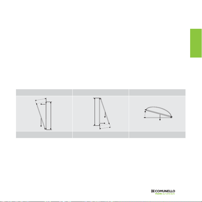
The Liwin chain actuator is intended only and exclusively for use for which it was designed, and the manufacturer
cannot be held responsible for damage due to its improper use. The actuator is intended exclusively for internal
installation to open top-hung and bottom-hung windows, skylights, dormer windows and roof windows. Any other use is
not recommended unless with the prior approval of the manufacturer. Install the actuator according to the instructions
shown in this manual.
Any apparatus serving and controlling the actuator must be produced according to the regulations in force and respect
the relevant standards issued by the European Community.
If the actuator is installed on a window at a height of less than 2.5 m from the floor and in buildings (public and
otherwise) in which the use of destination is not clear, it must be operated exclusively by a command which is not
accessible by public (key button).
The command button has to:
1) be placed at a height of 1500 mm from the floor
2) be positioned so that, at its activation, a person who carries the opening and closing has within its field of view all
the moving parts.
Do not wash the apparatus with solvents or jets of water. Do not immerse the apparatus in water.
Any repair must be carried out by qualified personnel (the manufacturer or an authorised service centre).
Always insist that only original spare parts are used.
Failure to use the original spare parts could compromise the correct operation of the product and the safety of people
or property, also annulling the effects of the guarantee enclosed with the apparatus.
In case of any problems or doubt, contact the point of sale where the product was purchased or the manufacturer
directly.
Cross section of cables Max length of the cable
1,50 mm2~ 100 m
0,75 mm2~ 50 m

26
3.1 Table of technical data and mark
The CE mark certifies that the actuator conforms to the essential health and safety requirements laid down by
European product directives. The CE mark can be identified by the relevant adhesive label applied to the outside of
the product, on which are shown some of the data shown in the following table:
3. TECHNICAL DATA
Liwin
Liwin 2W-Net
Liwin 3W-Net
Liwin 4W-Net
Liwin R
Liwin 2W-Net R
Liwin 3W-Net R Li-
win 4W-Net R
Model L35 230Vac ML35S140Hy00* ML35Sx40Hy00** ML35R140Hy00* ML35Rx40Hy00**
Model L35 24Vdc ML35S140Ly00* ML35Sx40Ly00** - -
Model L25 230Vac ML25S138Hy00* - - -
Power supply ac voltage 230 Vac 230 Vac 230 Vac 230 Vac
Power supply dc voltage 24 Vdc 24 Vdc - -
Frequency of ac voltage 50 Hz 50 Hz 50 Hz 50 Hz
Operation S2 4 min
Push/Pull strength L35 350 N F total X 0,7 350 N F total X 0,7
Push/Pull strength L25 250 N - - -
Stroke speed unloaded 18 mm/s
Protection class IP44
Double insulation ac yes
Double insulation dc low voltage
Motor voltage V ac L35 0,19 A 0,19 A 0,19 A 0,19 A
Motor voltage V ac L25 0,14 A - - -
Motor voltage V dc 1 A 1 A - -
Power L35 28 W 28 W 28 W 28 W
Power L25 22 W - - -
Operating temperature -5 / +50 °C
Strokes L35 50 – 100 – 150 – 200 – 250 – 300 – 350 – 400 – 420 mm
Strokes L25 200 – 250 – 380 mm
Closed limit switch on impact
Soft Start/Soft Stop yes / yes yes / yes yes / yes yes / yes
Obstacle detection yes yes yes yes
Connection in parallel yes ( max 30 actuators )
Synchronisation no yes no yes
Dimensions 390x38x73 mm
* Replace “y” with the colour code: 0B black, 0W white, 0G grey.
** Replace “x” with synchronisation value: 2 = two actuators, 3 = three actuators, 4 = four actuators.

27
ENGLISH
4.1 Types of power supply
The Liwin series of actuators is available in various models and colours in two electrical supply versions:
• 230 Vac - can be supplied with mains power 230 Vac (50 Hz) (with a tolerance of ±10%), with a three-core supply
cable: BLUE, neutral common; BLACK, open phase; BROWN, closed phase.
• 24 Vdc - can be supplied with a voltage of 24 Vdc with a two-core supply cable: BLUE, connected to the +
(positive) closed; BROWN, connected to the + (positive) open.
4.2 Calculation of the force necessary
The calculation is made without considering the loads due to atmospheric agents.
Key to symbols F = Force required to open in N (Newton)
P = Weight of the window (only moveable part) in kg (kilogrammes)
C = Opening travel of actuator in cm (centimetres)
H = Height of the openable part of the window in cm (centimetres)
Bottom-hung inward opening Top-hung outward opening Horizontal skylight
P
F
C
(B) HP
F
C
(A)
H
P
F
F = [(P / 2 ) x (C/H)] x 9.8 F = [(P / 2 ) x (C/H)] x 9.8 F = (P / 2) x 9.8
For all the W-net systems the total push force of the syncronized actuator con be calculated by creating a sum of the
force of every single actuator and the subtracting 30% of the force remaining.
4.3 Pack and tools required for assembling the actuator
The actuator is packed individually in a cardboard box. Each pack contains: electric actuator, 230 Vac 50 Hz or 24
Vdc, with electric supply cable, support brackets, fixing bracket for top-hung window, fixing bracket for bottom-hung
window, drilling template and instruction manual. Before starting to fit the actuator, we recommend preparing the
following fitting materials, tools and equipment: Metre rule or tape measure, pencil, drill/screwdriver, set of drill
bits for metal or wood, set of screw bits, electrical pliers, screwdrivers, screws and/or threaded inserts suitable for
the type of window material. AVOID using self-tapping screws and/or three-lobed screws on any metal windows.
4. ACTUATOR

28
5. PROGRAMMING FUNCTION WITH
R- CONTROL
LIWIN RADIO
UP
STOP
DOWN
PROG
SELC SELG
DIP-SWITCHES
DIP Function
1Storage of the transmitters
3Deletion of all the stored transmitters
2-4 Not used
5.1.DIP-SWITCH 1: STORAGE OF THE TRANSMITTERS
To store a transmitter TX1 on a blank actuator proceed as follows:
To store a transmitter on a blank actuator proceed as follows:
A Prepare the electrical connection to the main voltage 230 VAC, but do not connect the actuator
B Set the transmitter dip-switch no.1 into ON position (all the other dip-switches must be in OFF position)
C R6 control only: press the key SELC of the transmitter repeatedly, until displayed by the leds the selected
channel
D Connect the actuator to the 230 VAC voltage
E Within 5 sec press and hold (for about 3/4 sec) the key PROG of the transmitter TX1
F Release the key PROG
G Set the transmitter dip-switch no.1into OFF position
H Wait 10 sec
I Pressing the keys UP or DOWN, the actuator moves in opening/closing direction
To add another transmitter to the actuator it is necessary to use a remote control previously programmed
transmitter and proceed as follows:

29
ENGLISH
A R6 control only: press the key SELC of the already programmed transmitter repeatedly, until displayed by the
led the selected channel
B Set the dip-switches no.1 into ON position of both transmitters
C Press and hold for 15 seconds the key PROG of the transmitter 1 already programmed
D Release the key PROG of transmitter 1
E Within 5 seconds press and hold for 5 seconds the key PROG of the transmitter 2 to be programmed
F Set the transmitter dip-switch no. 1 of transmitters 1 and 2 into OFF position
G Wait 10 seconds
H Pressing the keys UP or DOWN the actuator moves in opening/closing direction
5.2.DIP-SWITCH 3: DELETION OF ALL THE STORED TRANSMITTERS
To delete all the transmitters stored on the actuator it is necessary using a remote control previously stored and
proceed as follows:
A Power only the actuator to be reset
B R6-CONTROL only: press the key SELC on the transmitter repeatedly until displayed the channel stored (by the
leds)
C Set the transmitter dip-switch no.3 into ON position
D Press and hold for at least 10 seconds the key PROG of the transmitter
E Leave the key PROG and set the remote dip-switch no.3 into OFF position

30
With bottom-hung windows, there is a danger of potential injury resulting from the window accidentally
falling.
It is OBLIGATORY to fit limiting arms (of the Series 1276 type), or an alternative safety system, of a suitable
size to prevent the window from accidentally falling down.
6.1 Installation sequence
- Check that the width of the window, where the actuator is due to be fitted, is more than 420 mm. Otherwise, it is
NOT POSSIBLE to fit the actuator.
- Check that the force required to open/close it (calculated according to the table under Point 4.2) is less than or
equal to that shown in the TECHNICAL DATA table.
- Try manually the window opening, checking for and if necessary eliminating any sticking points that could cause
a malfunction.
- Manually test the maximum opening of the window, checking that it is greater than the travel set by the actuator.
Top-hung outward opening window: Overall dimensions and fixing holes
27 325 27
17.5
54.4
414
99
37
38.5
10
Filo Serramento
Bottom-hung inward opening window: Overall dimensions and fixing holes
27 325 27
99.5
74 . 5
55
41
55
74 . 5
414
32.5
106 .3
Filo Serramento
6. INSTALLATION

31
ENGLISH
Bottom-hung inward opening window: Top-hung outward opening window:
CAUTION If the window is of the bottom-hung type, check that the limiting arms have been fitted to prevent the
window from accidentally falling down.
Bottom-hung inward opening window: With a pencil, mark the
mid-point “X” of the window frame.
Top-hung outward opening window: With a pencil, mark the
mid-point “X” of the window frame.
Bottom-hung inward opening window: Top-hung outward opening window:
telaio / frame / cadre / rahmen / armazón
finestra / window / fenêtre / fenster / ventana
telaio / frame / cadre / rahmen / armazón
Finestra a sporgere
Top-hungoutward opening
Fenêtreà l’italienne
Klappfenster
Ventanaprojectante
Finestra a vasistas
Bottom-hung inwardopening
Fenêtreà soufflet
Kippfenster
Ventanaabatible
telaio / frame / cadre / rahmen / armazón
finestra / window / fenêtre / fenster / ventana
telaio / frame / cadre / rahmen / armazón
Finestra a sporgere
Top-hungoutward opening
Fenêtre à l’italienne
Klappfenster
Ventanaprojectante
Finestra a vasistas
Bottom-hung inward opening
Fenêtre à soufflet
Kippfenster
Ventanaabatible
= =
Min 420 mm
= =
Min 420mm

32
Bottom-hung inward opening window: Top-hung outward opening window:
Pre-fit the support brackets to the frame using the alignment template.
Drill holes in the frame using the template supplied or the measurements shown on Page 7.
Fix the brackets and the fixings, using suitable screws.
Bottom-hung inward opening window: Top-hung outward opening window:
Stick the alignment template lable on the frame.
Drill holes in the frame using the template supplied or the measurements shown on Page 7.
Fix the brackets and the fixings, using suitable screws.
telaio / frame / cadre / rahmen / armazón
finestra / window / fenêtre / fenster / ventana
telaio / frame / cadre / rahmen / armazón
Finestra a sporgere
Top-hungoutward opening
Fenêtre à l’italienne
Klappfenster
Ventanaprojectante
Finestra a vasistas
Bottom-hung inward opening
Fenêtre à soufflet
Kippfenster
Ventanaabatible
telaio / frame / cadre / rahmen / armazón
finestra / window / fenêtre / fenster / ventana
finestra / window / fenêtre / f
telaio / frame / cadre / rahmen / armaz
Finestra a sporgere
Top-hungoutward opening
Fenêtre à l’italienne
Klappfenster
Ventana projectante
Finestra a vasistas
Bottom-hung inward opening
Fenêtre à soufflet
Kippfenster
Ventana abatible
telaio / frame / cadre / rahmen / armazó
finestra / window / fenêtre / fe
finestra / window / fenêtre / fenster / ventana
telaio / frame / cadre / rahmen / armazón
Finestra a sporgere
Top-hungoutward opening
Fenêtre à l’italienne
Klappfenster
Ventana projectante
Finestra a vasistas
Bottom-hung inward opening
Fenêtre à soufflet
Kippfenster
Ventana abatible
telaio / frame / cadre / rahmen / armazón
finestra / window / fenêtre / fenster / ventana
telaio / frame / cadre / rahmen / armazón
Finestra a sporgere
Top-hungoutward opening
Fenêtre à l’italienne
Klappfenster
Ventanaprojectante
Finestra a vasistas
Bottom-hung inward opening
Fenêtre à soufflet
Kippfenster
Ventanaabatible
telaio / frame / cadre / rahmen / armazón
finestra / window / fenêtre / fenster / ventan
finestra / window / fenêtre / fenster / ventana
telaio / frame / cadre / rahmen / armazón
Finestra a sporgere
Top-hungoutward opening
Fenêtre à l’italienne
Klappfenster
Ventana projectante
Finestra a vasistas
Bottom-hung inward opening
Fenêtre à soufflet
Kippfenster
Ventana abatible
telaio / frame / cadre / rahmen / armazón
finestra / window / fenêtre / fenster / ventan
finestra / window / fenêtre / fenster / ventana
telaio / frame / cadre / rahmen / armazón
Finestra a sporgere
Top-hungoutward opening
Fenêtre à l’italienne
Klappfenster
Ventana projectante
Finestra a vasistas
Bottom-hung inward opening
Fenêtre à soufflet
Kippfenster
Ventana abatible

33
ENGLISH
Bottom-hung inward opening window: Top-hung outward opening window:
Insert the side fulcrum pin into the support bracket
Move the actuator towards the window frame in order to insert the (opposite) side fulcrum pin into the support
bracket
Rotate the actuator, as shown in the following drawing, to fix it firmly.

34
Bottom-hung inward opening window: Top-hung outward opening window:
Rotate the actuator so as to allow the window to shut.
Rotate the actuator in the opposite direction so that the end of the chain can
be inserted correctly inside the bottom-hung window fixing.
Rotate the actuator in the opposite direction so that the end of the chain can
be inserted correctly inside the top-hung window fixing.
Join the chain to the fixing by inserting the relevant
locking pin.
Join the chain to the fixing by inserting the relevant
locking pin. Clip the cover in place.

35
ENGLISH
Bottom-hung inward opening window: Top-hung outward opening window:
Removal of end cap and rubber cover.
Positioning the DIP-switch

36
Select the stroke distance required by following the setting of the DIP-switches according to the scheme below.
Note: each DIP-switch has three possible positions.
Liwin 350N
Stroke Dip-switch 1 Dip-switch 2
420
Top Top
Middle Middle
Botton Botton
400
Top Top
Middle Middle
Botton Botton
350
Top Top
Middle Middle
Botton Botton
300
Top Top
Middle Middle
Botton Botton
250
Top Top
Middle Middle
Botton Botton
200
Top Top
Middle Middle
Botton Botton
150
Top Top
Middle Middle
Botton Botton
Stroke Dip-switch 1 Dip-switch 2
100
Top Top
Middle Middle
Botton Botton
50
Top Top
Middle Middle
Botton Botton
Liwin 250N
Stroke Dip-switch 1 Dip-switch 2
200
Top
Unavailable
Middle
Botton
250
Top
Unavailable
Middle
Botton
380
Top
Unavailable
Middle
Botton

37
ENGLISH
6.2 Minimum heights of the leaves
Consultinthetablethevaluesoftheminimumheightsoftheleavesrelativetothechainmotorsinthebottomhungversion.
Chain stroke “C” Min leaf height
50mm /
100mm /
150mm 300mm
200mm 650mm
250mm 1000mm
300mm 1400mm
350mm 1800mm
380mm 2000mm
400mm 2200mm
420mm 2400mm
DIMENSIONS
55
C
5
Motor rotation fulcrum
Leaf rotation hinge
H min
13.5

38
6.3 Electrical connection
Wire in the apparatus according to the electrical supply required by the actuator (see label on product), following
the table below.
230 Vac supply 24 Vdc supply
1
Blue
Neutral / Common
1
Blue
Positivo
2
Black
Phase / Open
2
Brown
Negativo
3
Brown
Phase /Closed
4
White Data (2/3/4 W-Net actuators)
4
White
Data (2/3/4 W-Net actuators)
5
Yellow Data (2/3/4 W-Net actuators)
5
Yellow
Data (2/3/4 W-Net actuators)
6
Green Data (2/3/4 W-Net actuators)
6
Green
Data (2/3/4 W-Net actuators)
Electric 230 Vac wiring Radio version wiring Electric 24 Vdc wiring
24 Vdc -
+
12
Electric 230 Vac wiring
(2/3/4 W-Net actuators)
Radio version wiring
(versioni 2/3/4 W-Net)
Electric 24 Vdc wiring
(2/3/4 W-Net actuators)
110/230V~ 50/60Hz F
N
123
4
5
6
4
5
6
4
5
6
24 Vdc -
+
4
5
6
4
5
6
4
5
6
12
230V~ 50Hz
13
F
N
110/230V~ 50/60Hz F
N
123
4
5
6
4
5
6
4
5
6
230V~ 50Hz
13
F
N
230V~50HZ
230V~50HZ

39
ENGLISH
6.4 Operating test
Press the control button and close the window, checking that:
A. The window is completely closed. If it is not, check that the gap between the window and the frame is bigger than
or equal to 0 mm. If necessary, insert spacers so as to obtain the correct gap.
B. The chain is perfectly vertical to the window frame. If necessary adjust the fixing bracket by using the screws and
slots.
Having reached the correct closing position, press the control button and open the window in order to check that the
actuator runs freely over the full travel set up.
Having achieved the required opening run, press the control button again to close the window. Once the window
has completely closed, check that the screws, supports and fixings are tightened correctly, and that the seals are
sufficiently compressed.
Installation completed
Bottom-hung inward opening window: Top-hung outward opening window:
Insert the rubber DIP-switch cover and close the end cap
CAREFUL!! - after installation the 4 covers must be perfectly closed.

40
7. MAINTENANCE, EMERGENCY ACTION &
CLEANING
If it becomes necessary to manually disconnect the window from the actuator due to: a power failure, mechanical
breakdown, maintenance, or cleaning the exterior of the window, follow the step sequence described on Page 11
in reverse order.
BEWARE OF THE DANGER of the window falling; as the window is free to fall, as it is no longer held up by the chain. Once
the maintenance or cleaning operations have been completed, repeat the sequence described on Page 11.
ATTENTION!
Before operating the actuator, please make sure that the product has been fixed at the right position
OK
no 2mm

41
ENGLISH
9. FAQ (frequently asked questions)
8. PROTECTION OF THE ENVIRONMENT
Some parts inside the actuator are not recyclable (plastic materials and electronic parts) and cannot be considered
normal refuse. They must be disposed of correctly. In case of doubt, consult the relevant refuse disposal body.
Question Cause Remedy
The actuator is not operating
No voltage supply
Check the electrical cut-out or safety switch
is “On”.
A cable may not be connected. With voltage
supplied | Check the actuator voltage corre-
sponds to voltage supply detected.
With voltage supplied Check the actuator voltage corresponds to
voltage supply detected
The actuator is not travelling
the distance required
The window opening is not as
required
Check that according to the table on Page
13 the DIP-switches are set for the correct
travel.
The chain is bent and not
perfectly linear
Detach the chain from the fixing and check
that the limiting arm allows the actuator
to travel the complete run. If this does not
happen, adjust the limiting arm so that the
actuator travels the whole distance..
The actuator pulls out the
screws
Fixings (bottom-hung window
and/or top-hung window)
are no longer fastened to the
frame
Check that suitable fixings have been used.
Check that, on closing, the chain is perfectly
perpendicular to the frame. If not, check
that the fitting was carried out according to
the Installation Sequence, 5.1.

42
a) In business relationships or in case of products sold for professional use, this warranty is limited to the repair
or replacement of product parts that FRATELLI COMUNELLO SPA acknowledges as defective, through equivalent
re-manufactured Products (the “Conventional Warranty”); the warranty does not include the costs necessary for
repairing or replacing the material (e.g. labour costs, rental of equipment etc).
b) The provisions contained in articles 1490 to 1495 of the Italian Civil Code shall not apply.
c) FRATELLI COMUNELLO SPA warrants the proper operation of the products within the limits indicated in a) above.
Unless otherwise agreed, the validity of the Conventional Warranty is 36 (thirty-six) months from the production
date, which can be found on the products. The Warranty shall be effective and binding on COMUNELLO only if the
product has been correctly installed and maintained in accordance with the installation and safety rules set out in
the documentation provided by COMUNELLO or otherwise available on the website http://www.comunello.com/
corporate/ general_conditions_sales/
d) The warranty does not cover: failures or damage caused by transport; failures or damage caused by defects in
the electrical system of the buyer and/or by carelessness, negligence, inadequate or abnormal use of such system;
failure or damage due to tampering carried out by unauthorized personnel or due to incorrect use / installation
(in this regard, system maintenance at least every six months is recommended) or the use of non-original spare
parts; defects caused by chemical agents and/or atmospheric phenomena. The warranty does not cover the cost
of consumables; in any event, COMUNELLO shall be entitled to a consideration for the work performed at the
Customer, where such work proves useless as the warranty did not apply or because the customer had used the
Comunello product in a negligent, reckless or incompetent manner, such that the proper use of the product could
have avoided the work.
e) Implementation terms: unless otherwise agreed, the right to the Conventional Warranty is exercised by showing
a copy of the purchase document (invoice) to COMUNELLO. Any defect must be notified to COMUNELLO within the
time limit of thirty (30) days from detection of the defect.
The action must be exercised within the limitation period of 6 (six) months from detection of the defect. The Product
parts for which the Customer requests application of the Conventional Warranty must be returned by the Customer
to FRATELLI COMUNELLO SPA, Via Cassola 64, 36027 Rosà (VI) Italy.
f) The Customer cannot claim compensation for indirect damage, loss of profits, loss of production and in any case
it cannot claim compensation for an amount that exceeds the value of the supplied components or products. All
transport costs for Products that have been repaired or to be repaired, although covered by the Conventional
Warranty, shall be charged to the Customer.
g) No external work carried out by Comunello technical staff is covered by the Conventional Warranty.
h) Specific amendments to the Conventional Warranty conditions described herein can be defined by the parties in
their commercial contracts.
i) The Court of Vicenza (Italy) shall be the place of jurisdiction for any dispute which will be settled according to
the Italian laws.
10. GUARANTEE
Other manuals for Liwin
1
This manual suits for next models
9
Table of contents
Languages:
Other Comunello Gate Opener manuals

Comunello
Comunello QUAD 24V HP User manual

Comunello
Comunello SHOWIN S45 10N SH User manual

Comunello
Comunello CONDOR 500 / ONE User manual

Comunello
Comunello CONDOR 500 / ONE User manual

Comunello
Comunello SHOWIN User manual

Comunello
Comunello FORT 3500 User manual

Comunello
Comunello CONDOR 220 User manual