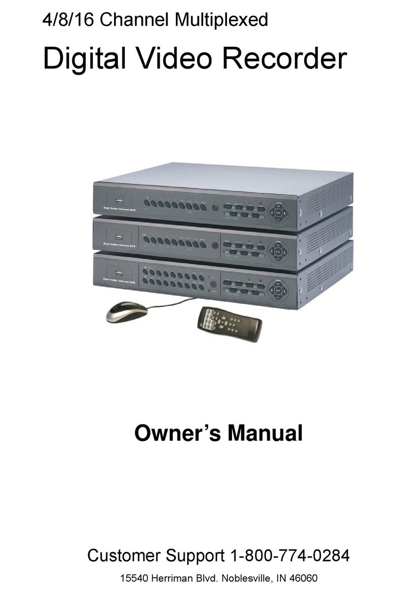
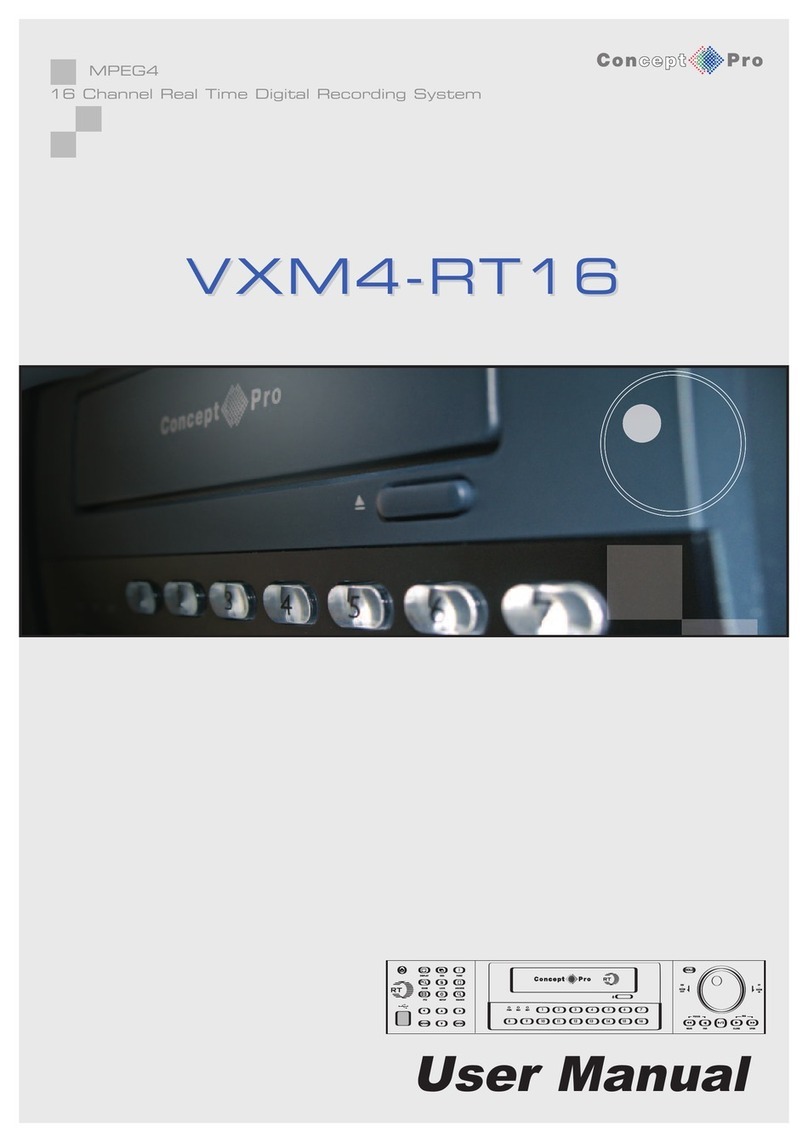
Concept Pro VXH960-4 User manual

USER MANUAL
4, 8 & 16 Channel Full HD DVR
VXH960-4 | VXH960-8 | VXH960-16

Copyright
This manual without the manufacturer’s approved copy and reprinted partially or in full, or translated into another language is prohibited.
Limitation of Liability
This product is designed to prevent re and theft is not the main means. We shall not be liable for accidents or damage by using this
product can result in liability for accidents or damage
In order to improve the performance of the product without prior notice to the product may be a rmware upgrade.

Content
Contents
Overview 1
1Safety Instruction
2Key Features
3 What’s included
4Front Panel
5Rear Panel
6Remote Control At a Glance
Installation 7
7Basic Layout
8Connecting to an external device
Getting Started 14
14 Log in / out
16 Live Screen At a Glance
System Setting 25
25 To enter to the System Setup menu
26 Camera Setting
32 Display Setting
36 Audio Setup
37 User Setting
39 Network Setup
43 System Setting
47 Storage
50 Event Set
Record Setting 60
60 To enter the Record Setup menu
60 Record Setup
Search 65
65 To enter to the Search menu while
in monitoring
66 Time search menu while in
playback mode
67 Thumbnail search menu
67 Event Search menu
Playback 68
68 Playback Control
70 Bookmarking
Archiving 71
71 To enter the Archive menu
72 Reserved data management
Web Viewer 74
74 What is the Web Viewer?
76 Live
80 Search
82 Setup
Mobile Viewer 93
93 VXH264 Pro APP
Archive Viewer 100
100 Getting started with the Backup Player
101 Backup Player At a Glance
Appendix 103
103 Appendix A: Speci cation
105 Appendix B. Troubleshooting (FAQ)
106 Appendix C: Con guring a Netgear DG384 router
109 Appendix D: Open Source License Report on
the Product

11
Remove the power supply before proceeding.
Check the input voltage (AC100V–AC240V) to the power supply before connecting it.
Keep the product away from humidity.
Ensure that all devices connected to the product are correctly earthed.
Do not connect multiple devices to a single power socket.
Keep the product away from dust or combustible substances (ex: propane gas).
Do not touch it with wet hand.
Do not insert a conductor in the vent of the ventilation
Do not apply excessive force to unplug the power cord.
When cleaning on the surface, use a dry cloth.
Do not wipe the product using water, paint thinner or organic solvents.
Do not dismantle, repair or modify the product by your own, contact your supplier.
Do not apply force to or shake it while in use.
Warranty is void if the “warranty void if broken” sticker is broken
Secure at least 18 centimeter of distance between cooling fan and wall for a proper ventilation.
Install the product on a fl at surface.
Keep it away from direct sunlight.
Concept Pro will not have any responsibility for any accident or damage that may occur during the use
of the VXH960. For your safety, we provide a few instructions about installation, control, and cleaning
of the product. Please read carefully and comply with the instructions. The warranty will be void if the
“warranty void if broken” sticker is damaged or has been removed.
Before installation
Comply with the following instructions to prevent a re, explosion, system failure shock. or electric
shock.
In operation mode
Comply with the following instructions to prevent a re, explosion, system failure or electric shock.
Disassembly & Cleaning
While in use
During installation
To prevent an accident or physcial injury to operate the DVR correctly, please comply with the following:
Overview Safety Instruction

2
Overview
Key Features
Overview
Up to 16 channels of 960H camera video can be displayed at 400 fps in real time
Up to 16 channels of 960H camera video can be saved at maximum 400 (PAL) fps.
Simultaneous recording and playback of maximum 16 channels (at 120 fps @ 960H)
Supports H.264 HP (High Pro le) CODEC
Auto alarm feature with self-diagnostics on the system (HDD S.M.A.R.T, system temperature,
network error, FAN error, etc.)
Supports dual streaming for remote access service
Supports HDD extension (eSATA)
Various search methods (time, event, bookmark and thumbnail)
Mass storage backup via USB port or FTP server
Supports remote access and search using web browser
Dedicated smart phone applications that can be used with iOS and Andriod
1080p Full HD GUI
This product is capable of receiving up to 16 960H video and audio inputs, it is also able to record onto
a hard disk drive in realtime, as well as providing monitoring, playback and backup footages in excellent
quality of 960H resolution. It also provides transferring of video and audio data to the networked external
devices, which allows a remote monitoring environment for computers and smart phones.

Overview
3 3
Overview
Mouse x1 User Manual CD x1
Terminal Blocks x2
Power Cable x1 User Manual x1
Screws (for fi xing rack mount)
Quick Guide x1
Rack Mounts
Remote Control x1
& Batteries (AAA x2)
Whats Included

4
Front Panel Overview
No. Name Description
1 IR Remote Control Receiver Receive the signal from the remote control.
2 USB For connecting USB devices such as a mouse or memory stick.
3 Status LED Show the status of power, recording or network connection together
with any corresponding alarm. 4
4 HDD 1~5 / eSata Indicates connection status of internal/external storage devices
1
3 4
2
1
3 4
2
4 Channel
8 & 16 Channel

5
Rear Panel
Overview
No. Name Description
1 VIDEO IN Video input terminal for cameras.
2 LOOP OUT Video output to send a signal to an external video device.
3 AUDIO OUT Port for speaker connection.
4SPOT Exclusive port for SPOT output only. (Connect to a monitor.)
5 Power Switch DVR power switch. Plug the power cord and turn this switch on.
6 100-240V (50/60Hz) Power input port.
7 AUDIO IN Port for audio input.
8 DIP Switch Switch to select a video type or an output type. Set to PAL
9 VGA VGA monitor video output port.
10 AUX Additional SPOT OUT port. (Connect to a monitor.)
11 HD-MONITOR HD monitor video output port (HDMI).
12 eSATA Connection port for external eSATA storage.
13 USB Used for connecting USB storage or mouse.
14 WAN(UPLINK) Network port for connection to the Internet, router or hub.
LAN(DOWN LINK) Port for connecting the dedicated network device. Do not share it with other device.
15 ALARM IN Alarm input port.
ALARM OUT Alarm out port. (TTL)
RELAY Relay terminal port.
RS485 Ports for communication with external devices such as PTZ camera and system keyboard.
RS232 Connection ports for signal cables to external devices such as PTZ camera, POS and ATM devices.
4 Channel
1
82 4 7 11 913 14 16
10 315
1
15 14 13 12 11 10 9 8 7 6 5
234
1
15 14 13 12 11 10 9 8 7 6 5
234

6
Overview
Remote Control at a Glance
Power
Turn on or off the power.
Search
Display the search window
Archive
Display the backup window
Channel
Function as channel selection button
in live or playback mode, or used for
entering the password.
Display
Switch the split mode
SEQ
Switch the sequence mode
Snapshot
Take a snapshot of the video
pqtu
Used to change the direction or
adjust the play speed in playback
mode.
Exit
Exit from the current screen and
return to the previous screen
Enter
Select a menu item or apply your
settings.
Logout
Log out
Panic
Start the emergency recording
Alarm
Show the alarm status with a popup
window
Setup
Display the system setup menu
ID
Set the remote contol ID
Log
Display the log list
Audio
Display the audio channel selection
window
Keylock
Lock the operation unit
Reserve
Reserve the current video
Menu
Dislpay the tool bar on the live
screen
pqtu
Use to move through the menus
Zoom/PTZ
Enter the PTZ or digital zoom mode
and control the operation
Change the remote control ID
The remote control works only if the remote control ID matches that speci ed on the DVR.
If multiple DVRs are used with a single remote control, use the ID button to set the remote control ID.
Only the ID-matching the DVR can be controlled.
From <SYSTEM> - <CONTROL DEVICE> under the System Setup menu,
set the <REMOTE CONTROLLER ID> and press <APPLY >.
Select between 00 and 99. For more details, refer to <SYSTEM SETUP>.
Press the [ID] button on the remote control. The default remote control ID is 00.
Use the number buttons to provide a two-digit ID. If you want to enter 01, for instance,
enter the number 0 and 1 in sequence.
Check if the remote control ID is set properly by manipulating the remote control.
To reset the ID to 00, press and hold the [ID] button.
7
Installation Basic Layout
Precautions
Since the cable quality may aff ect the video quality depending on the distance between the camera and DVR, it is
recommended to consult an authorized installer when installing the DVR.

8
Connecting to an external device Installation
This product supports 1080p 60 Hz HDMI monitors and regular monitors that support VGA inputs.
Connect a HDMI cable to the port on the rear of the VXH960 or use a VGA cable to connect the
DVR with a VGA monitor
Once the product is set to NTSC or PAL connect cameras of the corresponding
videostandard for proper operations.
Setting the product to NTSC or PAL decides available display output modes too.
R The monitor’s displaying operates at 50Hz if the product has been set
to PAL output and the connected monitor supports both 50Hz and
60 Hz inputs.
For NTSC setting, it works at 60 Hz.
!Make sure to connect the product to a monitor that supports 1920x1080
at 60Hz.
Power Connection
Apply power to DVR main unit, and connect the provided DC 48V power supply adaptor to the external
PoE switch (Power over ethernet).
Plug the power cable into the unit whilst the power is off at the wall.
Arrange up the cables and be careful not to peel off the cable coating.
Do not place the power cord under the carpet or rug. The power cord is usually
earth-grounded. However, even if it’s not earth-grounded, do not modify it for earth-grounding.
Do not insert multiple devices in a single power socket. Otherwise, it may cause a power
overload.
For a stable power supply, this product provides two separate separate adaptors and two
corresponding AC cords by factory default. Make sure all cables are connected properly.
Power Connection
Connecting to a
monitor

99
Connecting to an external device
Installation
To connect the alarm input signal
Connect the signal line of an alarm input device such as sensor to the rear [ALARM IN] port.
1. Loosen the screws on both the alarm input port and [GND] port of the provided terminal block plug.
2. Insert one end of alarm signal cable through the [IN1] or [IN8] terminal hole below the screw hole, and then
fasten the screw
3. Insert the ground signal wire into the hole of the [GND] port, and tighten the screw.
4. To check correct attachement of the cable, stop pushing and gently pull the cable and test whether it disconnects.
To disconnect the cable, push the bottom side of the terminal block and pull out the cable.
To connect the alarm output signal
Connect the signal line of an alarm output device to the rear [RELAY] port.
1. Loosen the screws on the [NO] and [NC] ports and the [COM] port of the provided terminal block plug.
2. Insert the alarm signal wire into the hole of the [NO] or [NC] input port.
Check the relay output type of Normal Open or Normal Close before selecting a proper type (NO or NC).
> NO (Normal Open): Normally Open but switching to Close if an alarm out occurs.
> COM: Insert the grounding wire.
> NC (Normal Close): Normally Close but switching to Open if an alarm out occurs.
3. Insert the ground signal wire into the hole of the [COM] port.
Or, you can connect the signal cable of the alarm output device to the [ALARM OUT] port on the rear side.
1. Loosen the screws on the [AO1] and [AO8] ports and the [GND] port of the provided terminal block plug.
2. Insert the alarm signal wire into the hole of the [AO1] or [AO8] input port
3. Insert the ground signal wire into the hole of the [GND] port
4. To check the correct attachment of the cable, stop pushing and gently pull the cable and test whether it disconnects.
To diconnect the cable, push the bottom side of the terminal and pull out the cable.
5. Put the wire-connected terminal block in the rear port.
Alarm I/O
Connection

1010
Connecting to an external device Installation
RS-485 Connection
Connect a PTZ Camera or Keyboard Controller.
After connecting the control device, be sure to match the connection settings between DVR and device.
Communication settings are in <Control Device>. (page 46)
1. Use a signal cable to connect the [D+] port of the terminal block plug and the [D+] port of the keyboard controller.
2. Connect the [D+] port of the terminal block plug and the [D+] port of the keyboard controller.
3. Connect the [GND] port of the terminal block plug and the [GND] port of the keyboard controller.
R For RS-485 communication con guration, refer to the user’s manual of the applicable PTZ camera or
keyboard controller.
You can connect an audio output device such as speaker ampli er.
Connect the audio input device such as microphone to the rear Audio In port, connect the audio
output device such as speaker ampli er to the Audio Out port.
Communication
Port
Audio Device
Connection

11
Installation Connecting to an external device
If the internal storage space is insuffi cient, you can extend your storage capacity by adding an eSATA
storage device to the rear eSATA port.
! Using devices other than recommended eSATA products may cause a serious problem.
You can connect and use USB storage devices to backup recorded video, saving snapshots,
rmware updating, importing/exporting user con gurations. A USB mouse can be connected to
control the VXH960
eSATA Storage
USB Device
! If you need to connect a USB HDD with a high power consumption, it is recommended to use a
separate power source for that HDD.

12
Network Connection Installation
Network
Connection
PC connection in the local network
You can connect the VXH960 to a network so that it can be accessed via a PC.
1. Connect the [WAN(UPLINK)] port in the rear panel to the router or hub.
R The LAN (DOWN LINK) port is reserved and only for servicing and development.
(Do not connect devices to this port.)
2. Connect the local PC to the router or hub.
3. Enter the address in the Web browser of your PC in the format of: “http://IP address:Web service port”
(Ex: http://192.168.0.23:8080) The web service port is set to 8080 by default. From the Network
Setup screen, you can change the port number.
R If using the dedicated PC S/W, refer to the user manual of the program.
4. Provide the ID and password bfore logging in, then you can view the monitoring screen.
Factory defaults are: User ID: ADMIN, Password: 1234
! For security purpose, change the password before you use the product for the rst
time after purchasing it.

13
Network Connection
Installation
PC connection from the network
You can connect the DVR to a PC or mobile device on the same network and control it on the PC or mobile device
1. Connect the [WAN(UPLINK)] port to the router or switch on the
! The LAN (DOWN LINK) port is reserved and only for servicing and development.
(Do not connect devices to this port.)
2. If using the router, set the port forwarding and ener the DDNS or IP address in the address bar of a
web browser on the PC, dedicated software or smart phone.
For the IP and DDNS address settings, refer to “Network Setup”. (page 39)
3. If the MAC address of the DVR is 00-11-5F-12-34-56 and the web port number s 8080, enter
“http://00115f123456.dvrlink.net:8080” in the address bar of the web broswer. If you have renamed
DDNS as “mydvr”, you can enter http://mydvr.dvrlink.net:8080 in the address bar of the web broswer.

14
Log-in / Log-out Getting
Started
Start
1. Connect the power adapter to the poer input port on the DVR’s rear side
!Make connection when the power is not applied yet..
2. The front LED turns on and it will be when the unit boots up, you
will also see the boot up screen
3. When the booting process is completed, the live screen then the login
screen appears
Log Out
To prevent unauthorized access, it is recommended to log out when
you leave the screen.
R Hover the cursor near the bottom of the screen to display the
menu.
1. In the monitoring screen, click <MENU> in the bottom left corner of the
screen and then click <LOGOUT>, or press the [LOGOUT] button on
the remote control.
2. While logged out, Search, Backup, System Settings, Record
Settings and Exit menus are unavailable to use.
Log In
To access the menus of the DVR, you need to log in.
1. When the system starts, the login screen appears.
2. Select a user and provide the password.
The default password of the “ADMIN” account is “1234”.
3. Click <OK>.
If the login information is correct and valid, you will
see the live screen.
! For security purpose, change the password before you
use the product for the fi rst time

15
Log-in / Log-out
Getting
Started
System Shutdown
1. In the monitoring screen, click <MENU> in the bottom left corner of the
screen click <SHUTDOWN> the system, or press the [POWER] button
on the remote control.
2. Use the virtual keyboard to enter the password.
3. Be sure to turn off the power switch on the rear panel.
! If you turn off the system in an abnormal manner such as
removing the power cord while the system is in operation,
the disk will create or increase the bad sectors, causing
data loss and shortening the life cycle of the disk.

16
Live Screen at a glance Getting
Started
The live screen largely consists of four components: video window, status bar, timeline zone and quick menu
Icons used in the video window.
ITEM Description
Camera ID Show the camera ID.
Record Mode Icons Displayed if an event recording is reserved.
Display if continuous recording is active
Display if an alarm recording is active.
Display if a motion event recording is active.
Display if emergency recording is active.
Audio I/O Icons Displays if the audio signal of the connected camera is operational.
Motion Detection Icon Displays if motion detection is active.
Video Window
Video Window Quick Menu
Timeline
Status Bar

17
Press the qbutton on the remote control, or place the mouse in the lower area of the screen to display the status bar.
ITEM Description
Menu Button Select either the system setup, search and archiving menu.
User ID Show the ID of the user who has currently logged in.
Screen Control Buttons Edit the screen layout to show the status bar and timeline at all times or only when
the mouse cursor hovers on the status bar/timeline.
Select a split screen mode.
Select Auto Sequence Mode.
When a user arranges channels on desired tiles of split screen, such setting is listed
for later access. Selecting a screen setup directly switches the screen mode as con gured.
Display or hide the OSD menu on the screen.
PTZ Move to the PTZ screen. You can control the PTZ operations of a PTZ-compliant
camera on the PTZ screen.
Zoom Activate the Digital Zoom.
Quick Log Display the log list of the recent recording events.
Audio Channel Selection Button You can use the camera supporting the audio input to listen to the audio.
Panic Record Start/stop the panic recording.
Alarm Indicator Turns on if an event occurs. Click this to check the information of the event that occurred.
Network Connection Status Check if a connection is made to the networok, a PC or a mobile device. Click
this to view the details of the concurrent users and to check the network connection status.
For more information, refer to “Network Setup”. (Page 39)
Disk Space Show the disk space information. If you have set the disk overwrite mode, it will be
displayed “OW” (Over Write) from the start point of the overwriting. Click this to view
the details of the disk status. For more information, refer to “Disk Operations”. (page 48).
Date & Time Display the current time and date.
Live Screen at a glance
Getting
Started
Status Bar
This manual suits for next models
2
Table of contents
Other Concept Pro DVR manuals

Concept Pro
Concept Pro VXH5AHD-4 User manual

Concept Pro
Concept Pro VXM4-4 User manual

Concept Pro
Concept Pro VXH264D-16 User manual

Concept Pro
Concept Pro VXH264-4 User manual

Concept Pro
Concept Pro H.264 User manual

Concept Pro
Concept Pro VXM4-16 User manual

Concept Pro
Concept Pro VXH5AHDE-8 User manual

Concept Pro
Concept Pro HD-iP LITE VHDIPL-32-4 User manual

Concept Pro
Concept Pro VXH5AHDL-4 User manual

Concept Pro
Concept Pro VXM4-RT16 User manual