manuals.online logo
Brands
  1. Home
  2. •
  3. Brands
  4. •
  5. Connection
  6. •
  7. Indoor Furnishing
  8. •
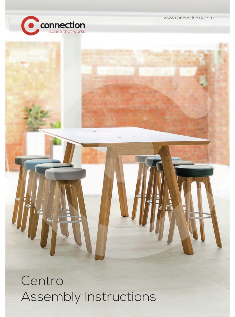
  9. Connection Centro User manual

Connection Centro User manual

Centro assembly
instructions
connection.uk.com
www.connection.uk.com
Preparation - Components
Remove all packaging from each component and lay them on the floor.
A Long oak fascia
B Short oak fascia
C Steel support frame with underside cover attached
D Table tops*
E Power module covers**
F Legs
G Power module housing (and any specified power modules)**
*Tables shorter than 2.6 metres will have one table top.
**These components are included alongside tables with optional power modules or cutouts only.
A
B
C
D
E
F
G
www.connection.uk.com
Preparation - Fixing kit
Your table should be supplied with a fixing kit in a sealed plastic bag. Empty its contents onto a suitable surface.
A Allen head bolts (not to be confused with larger allen head bolts pre-installed in legs)
B Washers
C Furniture bolts
D Double ended pins
E Hex head bolts*
F Button head bolts
* These fixings are included alongside tables with optional power modules only.
A
BC
E
D
F
www.connection.uk.com
Assembly
We advise that assembly of a Centro table requires two
people.
1. Remove the pre-installed allen head bolts and washers from one leg and keep these separate from any other fixings.
2. Lift the steel support frame from one end, leaving the other end on the floor.
3. Using the allen head bolts and washers removed in step 1, use these to loosely fix the first leg in place.
4. Repeat steps 1 to 3 for the remaining three legs.
Please note: If your Centro table has been specified with
optional power modules or cutouts, first ensure the cable
managed leg is installed at the corner of the table closest to
the power outlet or floor box.
1 2 3
4
4A
Cable managed leg
and cutout
www.connection.uk.com
5. Using the button head bolts, loosely attach the short oak fascias in the highlighted positions.
6a. Again, using the button head bolts loosely attach the long oak fascias on both sides in the highlighted alternating
positions.
6b. Once all fascias are attached and aligned with the legs, tighten all button head bolts to secure their position.
5
6
7. To prepare frame for attachment of table top, remove all screws attaching the underside cover and place to one side.
7
www.connection.uk.com
8. Place a table top onto the structure and ensure it is located on the fixtures.
9. Using the allen head bolts and washers, secure the table top to the structure. For tables under 2.6 metres - with a
single table top, fix both ends of the table top to the structure and jump to step 13.
10. Insert four double ended pins into the table top that has been fixed to the structure.
11. Place the second part of the table top onto the structure and offer it up to the pins from the first part of the table top
using the biscuits for alignment. Tighten all connectors equally.
12. As in step 9, using the allen head bolts and washers, secure the second part of the table top to the structure.
13. The table top now needs to be secured further, underneath the structure. Using furniture bolts, secure the table top to
the steel support frame in the fixing locations highlighted in image 13a and 13b.
Please skip to step 21 if your table is not specified with optional power units.
8 9
10
For tables 2.6 metres and over with two-part table tops
11 12
13a 13b
x4
www.connection.uk.com
14. Pull the wire from the power module through the power module housing as shown in image 14.
15. Begin by hand tightening the supplied screws into the power module.
Please note: power modules are orientated upside down so that a standard plug wire will face upwards.
16. And tighten using a screwdriver or power drill in a low power mode.
17. Locate the power module fascia.
18. Tighten screws securing power module fascia using a screwdriver or power drill in a low power mode.
19. Locate the power module housing and secure using four hex head bolts.
For tables with optional power units
Continued overleaf...
14 15 16
17 18
19
www.connection.uk.com
Cable
managed leg
Underside cover
To floor box
Cable
20. Bring the cable from the power unit(s) through the hole in the steel support frame and down the cable managed leg
pushing into place the cover.
20
www.connection.uk.com
21. Fix the underside cover back into place with the screws removed in step 7.
21
© Connection Seating Limited 2015. All rights reserved.
Head Office
Dogley Mills
Penistone Road
Fenay Bridge
Huddersfield
West Yorkshire
HD8 0LE
Tel: 01484 600 100
[email protected]
London Showroom
31 Great Sutton Street
Clerkenwell
London
EC1V 0NA
Tel: 020 7253 9877
www.connection.uk.com

Other manuals for Centro

1

Other Connection Indoor Furnishing manuals

Connection Tubes Series User manual

Connection

Connection Tubes Series User manual

Connection Platforms User manual

Connection

Connection Platforms User manual

Connection Centro User manual

Connection

Connection Centro User manual

Connection Tryst Booth User manual

Connection

Connection Tryst Booth User manual

Connection Cubbi User manual

Connection

Connection Cubbi User manual

Connection Tier User manual

Connection

Connection Tier User manual

Connection Hive User manual

Connection

Connection Hive User manual
Connection Co.Table User manual

Connection

Connection Co.Table User manual
Connection Hive User manual

Connection

Connection Hive User manual
Popular Indoor Furnishing manuals by other brands

Itatiaia VEGAS BALC-120 3PT1G quick start guide

Itatiaia

Itatiaia VEGAS BALC-120 3PT1G quick start guide

Okamura Arco 865JAT Assembly & instruction manual

Okamura

Okamura Arco 865JAT Assembly & instruction manual

Furniture of America FOA-AC240 Assembly instructions

Furniture of America

Furniture of America FOA-AC240 Assembly instructions

Refined Feline Metropolitan Cat Condo Assembly instructions

Refined Feline

Refined Feline Metropolitan Cat Condo Assembly instructions

Sonder Emerson Dining Table manual

Sonder

Sonder Emerson Dining Table manual

Kwik-Wall 3050 INSTALLATION PROCEDURE

Kwik-Wall

Kwik-Wall 3050 INSTALLATION PROCEDURE

Argos Ohio 309/5256 Assembly instructions

Argos

Argos Ohio 309/5256 Assembly instructions

Allen + Roth 1227WC-24-326 manual

Allen + Roth

Allen + Roth 1227WC-24-326 manual

Wampat W04E4151R Assembly instructions

Wampat

Wampat W04E4151R Assembly instructions

Furniture of America FOA7887D Assembly instructions

Furniture of America

Furniture of America FOA7887D Assembly instructions

cef Creation Cube Assembly instructions

cef

cef Creation Cube Assembly instructions

Criterion MENTORWUL Assembly & instruction manual

Criterion

Criterion MENTORWUL Assembly & instruction manual

RIAB Lectern instruction manual

RIAB

RIAB Lectern instruction manual

Glacier bay ROCARA ROCVGY4222D Use and care guide

Glacier bay

Glacier bay ROCARA ROCVGY4222D Use and care guide

Lightolier POINT POWER JACK Instructions for maintenance reference

Lightolier

Lightolier POINT POWER JACK Instructions for maintenance reference

Project Source 999-LUT18WHT manual

Project Source

Project Source 999-LUT18WHT manual

Desalto EVERY Assembly instruction

Desalto

Desalto EVERY Assembly instruction

BOMBAY 2032474 quick start guide

BOMBAY

BOMBAY 2032474 quick start guide

manuals.online logo
manuals.online logoBrands
  • About & Mission
  • Contact us
  • Privacy Policy
  • Terms and Conditions

Copyright 2025 Manuals.Online. All Rights Reserved.