ZIEHL TR 800 Web User manual

(Date / Name): 16.04.2009 Sc Drawing no.: 12280-0701-00
Page 1 of 24 Name: TR 800 WEB
ZIEHL industrie-elektronik GmbH + Co KG, Daimlerstr.13, D-74523 Schwäbisch Hall, Tel.: +49 791 504-0, Fax: -56, email: info@ziehl.de
Operating Manual
Universal-Relay TR 800 Web
MINIPAN
®
digital panel meters, temperature
-
and mains controlling,
special purpose instruments for customer requirements www.ziehl.com

(Date / Name): 16.04.2009 Sc Drawing no.: 12280-0701-00
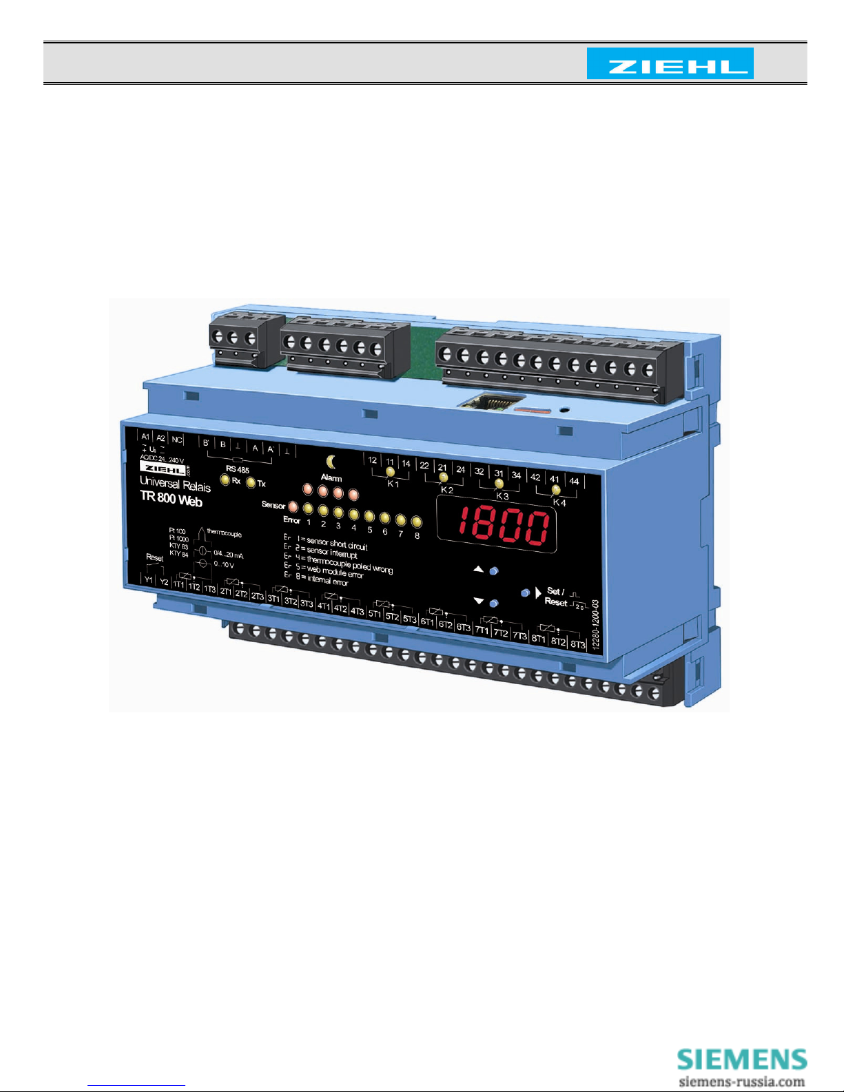
Page 2 of 24 Name: TR 800 WEB
ZIEHL industrie-elektronik GmbH + Co KG, Daimlerstr.13, D-74523 Schwäbisch Hall, Tel.: +49 791 504-0, Fax: -56, email: info@ziehl.de
Table of contents
1. Application and short description .................................................................................. 3
2. Overview of functions...................................................................................................... 3
3. Connection Plan ............................................................................................................... 3
4. Display and controls ........................................................................................................ 4
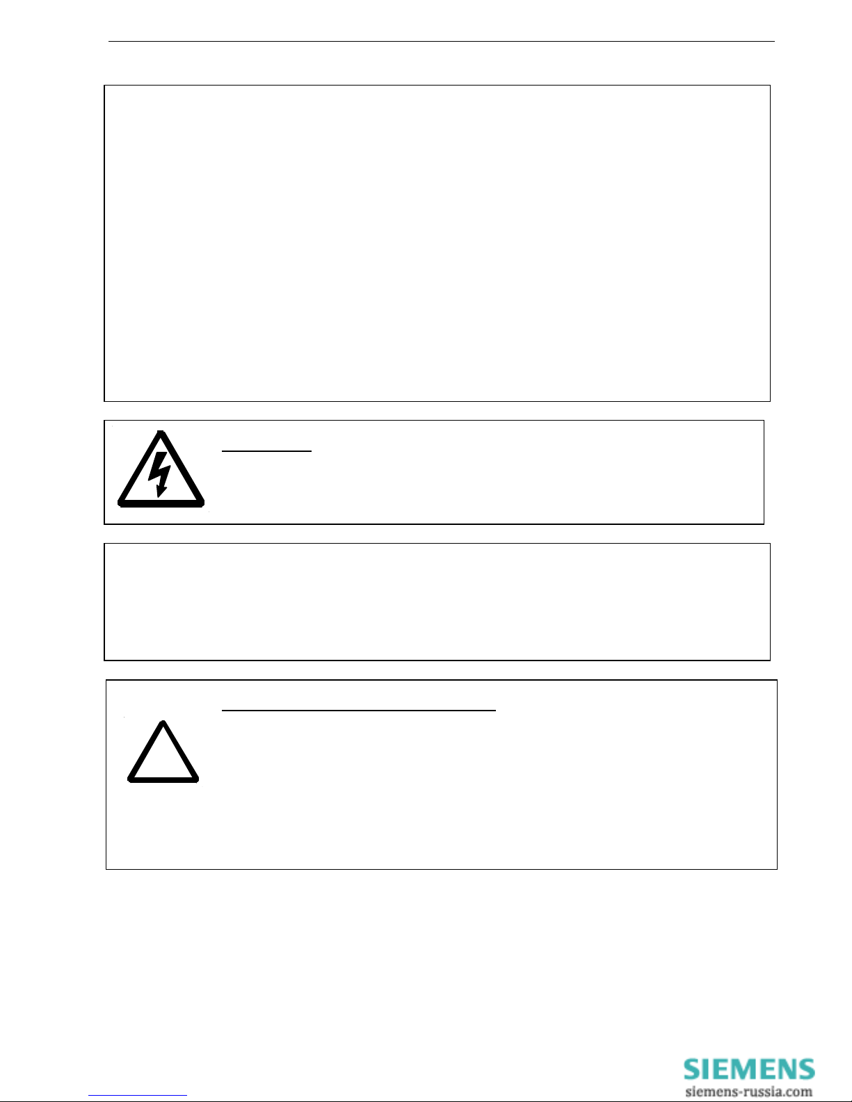
5. Important Informations .................................................................................................... 5
6. Installation ........................................................................................................................ 6
7. Detailed description ......................................................................................................... 6
8. Start-up operation (commissioning)............................................................................... 7
8.1 General instructions on operating................................................................................. 7
8.2 Display mode................................................................................................................ 7
8.3 Menu mode................................................................................................................... 7
8.4 Info mode ..................................................................................................................... 7
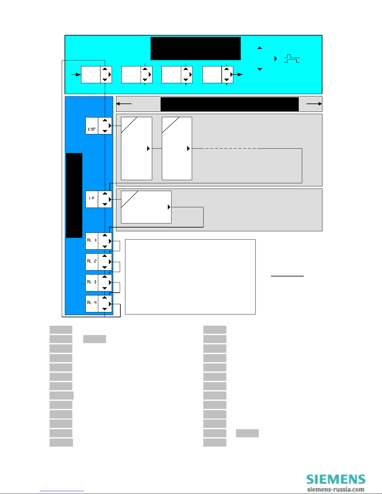
8.5 Short operating diagram ............................................................................................... 8
8.6 Overview of commissioning.......................................................................................... 9
8.7 Switching on the unit .................................................................................................... 9
8.8 Connection to network and controls ............................................................................. 9
8.9 Find the unit in the network ........................................................................................ 10
8.9.1 DHCP server ....................................................................................................... 10
8.9.2 Default IP- Adress 10.10.10.10 ........................................................................... 10
8.9.3 Bonjour................................................................................................................ 11
8.9.4 UPnP................................................................................................................... 11
8.9.5 Information about the login window ..................................................................... 11
8.10 Make the basic network settings................................................................................. 12
8.11 Sensor settings........................................................................................................... 13
8.12 Configuring the alarms ............................................................................................... 14
8.13 Alarm email................................................................................................................. 15
8.14 System ....................................................................................................................... 15
8.15 User management/access control .............................................................................. 17
8.16 Logging (see also: 9.4 FTP Upload)........................................................................... 17
8.17 View measurements and alarms, sensor simulation................................................... 18
8.18 Time-dependent control / Scheduler........................................................................... 19
9. Ethernet protocols ......................................................................................................... 20
9.1 UDP............................................................................................................................ 20
9.2 Modbus TCP............................................................................................................... 20
9.3 SNMP (Option) ........................................................................................................... 20
9.4 FTP Upload (Option) .................................................................................................. 20
10. RS485 interface ............................................................................................................ 20
10.1 Ziehl Standard Protocol .............................................................................................. 20
10.2 Modbus RTU .............................................................................................................. 20
11. Maintenance and Repair.............................................................................................. 20
12. Troubleshooting........................................................................................................... 21
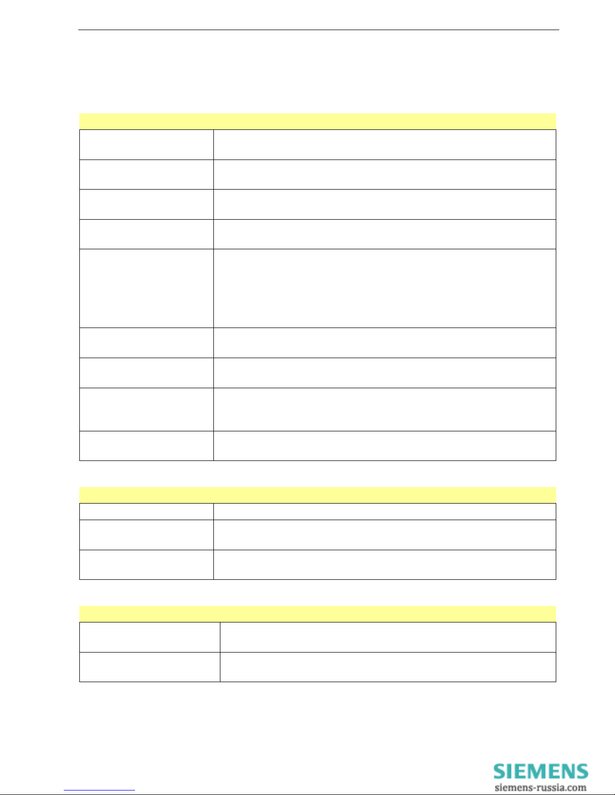
13. Technical Data.............................................................................................................. 22
14. Housing design V8....................................................................................................... 24

(Date / Name): 16.04.2009 Sc Drawing no.: 12280-0701-00
Page 3 of 24 Name: TR 800 WEB
ZIEHL industrie-elektronik GmbH + Co KG, Daimlerstr.13, D-74523 Schwäbisch Hall, Tel.: +49 791 504-0, Fax: -56, email: info@ziehl.de
1. Application and short description
Web-IO Universal Relay with ethernet-interface and 8 inputs for temperatur-sensors
and other analog signals.
The TR 800 Web can be connected to the internet or an intranet and operated via TCP/IP
from a normal PC with a suitable browser (tested with IE 7 and Firefox 3). No special
software and no special instruction is required.
The Universal Relays TR 800 monitors and logs signals from up to 8 inputs.
Up to 8 limits (one per input) can be programmed for each of the 4 output-relays.
2. Overview of functions
•8 measuring inputs:
oPt 100, Pt 1000 in 2- or 3-wire
oKTY 83 or KTY 84
oThermocouples type B, E, J, K, L, N, R, S, T
oDC 0-10 V, DC 0/4-20 mA
oResistance 500 Ohm, resistance 30 kOhm
•4 relay-outputs (each potential-free change-over contact)
•Ethernet interface (http, https, UDP, Modbus, Bonjour, UpNP, SNMP)
•RS485 interface (Standard Ziehl- and Modbus RTU- protocol)
•Universal power-supply AC/DC 24-240 V
•Integrated webserver for configuration, readout of measured data, user-management
email-alarms, data- and alarm-logging
•Time-dependent control (day/night)
•realtime clock with synchronisation with timeserver
3. Connection Plan
1) Terminating resistor active: Bridge A to A’ and B to B’

(Date / Name): 16.04.2009 Sc Drawing no.: 12280-0701-00
Page 4 of 24 Name: TR 800 WEB
ZIEHL industrie-elektronik GmbH + Co KG, Daimlerstr.13, D-74523 Schwäbisch Hall, Tel.: +49 791 504-0, Fax: -56, email: info@ziehl.de
4. Display and controls
1, 2 LEDs (yellow) RS485 interface
•Rx flashes briefly: Unit is receiving data via the RS485 interface
•Tx flashes briefly: Unit is transmitting data via the RS485 interface
•Rx and Tx flash/illuminate during firmware update
3 LED (red) Sensor error
•Illuminated: Fault in a sensor circuit
4 LEDs (red) alarm
•Illuminated: Alarm (1-4) has occurred
•Flashes briefly (1:4): Response delay is running
•Flashes long (4:1): Backshift delay is running
•Flashes uniformly (1:1): Ready for reset, reset with key
Press "SET/RESET" ≥2s or ext. Reset Y1/Y2
5 LED (yellow) Night
•Illuminated: Limits for "Night" (can be set via browser) are active
6 LEDs (yellow) sensors
•Illuminated: Displays the sensor value belonging to the LED in the
digital display
•Flashes: Sensor error in the corresponding sensor circuit
7 LEDs (yellow) relay state
•Illuminated: The relay belonging to the LED is picked up
•Off: The relay belonging to the LED is released
8 Digital display (4 digits)
•Display of sensor value
•Display of error codes
•Display of menu and configuration mode
9,10 Up button / Down button
•Change into the menu mode (see Operating instructions Point 8.3)
11 Set/Reset button
•Press briefly: Displays the next sensor (sensor LED illuminates)
•Press for 10 s: Displays the software version (e.g. 0
00
0-
--
-00
0000
00)
12 LED (yellow) Displays Ethernet transmission speed
•Off: 10 Mbps On: 100 Mbps
13 LED (green) Displays Ethernet data traffic
•Flashes during active data transmission
14 IP address slide switch
•Towards Ethernet jack: IP address 10.10.10.10
•Towards reset button: IP address User (set via webbrowser)
15 Webserver reset button
•Internal webserver restarts when pressed (duration ca. 1 minute)

(Date / Name): 16.04.2009 Sc Drawing no.: 12280-0701-00
Page 5 of 24 Name: TR 800 WEB
ZIEHL industrie-elektronik GmbH + Co KG, Daimlerstr.13, D-74523 Schwäbisch Hall, Tel.: +49 791 504-0, Fax: -56, email: info@ziehl.de
5. Important Informations
To use the equipment flawless and safe, transport and store properly, install and start
professionally and operate as directed.
Only let persons work with the equipment who are familiar with installation, start and use
and who have appropriate qualification corresponding to their function. They must observe
the contents of the instructions manual, the information which are written on the equipment
and the relevant security instructions for the setting up and the use of electrical units.
The equipments are built according to DIN / EN and checked and leave the plant according
to security in perfect condition. To keep this condition, observe the security instructions with
the headline „Attention“ written in the instructions manual. Ignoring of the security
instructions may lead to death, physical injury or damage of the equipment itself and of other
apparatus and equipment.
If, in any case the information in the instructions manual is not sufficient, please contact our
company or the responsible representative.
Instead of the industrial norms and regulations written in this instructions manual valid for
Europe, you must observe out of their geographical scope the valid and relevant regulations
of the corresponding country.
ATTENTION
Dangerous electrical voltage!
May lead to electrical shock and burn.
Before beginning of work switch unit and equipment free of voltage.
Observe the maximum temperature permissible when installing in switching cabinet.
Make sure sufficient space to other equipment or heat sources. If the cooling
becomes more difficult e.g. through close proximity of apparatus with elevated
surface temperature or hindrance of the cooling air, the tolerable environmental
temperature is diminishing.
ATTENTION! Connection of sensors
The inputs 1T1, 1T2, 1T3 to 8T3 and RESET Y1, Y2 are not potentially
separated from output RS485. Temperatur-sensors must have
a sufficient insulation.
Only signals according to SELV (Safety Extra Low Voltage) may be
connected.
The pluggable terminals of the measuring inputs have a special
contact-material and may only be used for the connection of the
sensors.
Attention! Universal power supply
The unit is equipped with an universal power supply, that is suitable for DC- and AC-
voltages. Before connecting the unit to the current, make sure that the allowed scope of
voltage of the control voltage Us, written on the lateral type plate, corresponds to the supply
voltage of the unit.
!

(Date / Name): 16.04.2009 Sc Drawing no.: 12280-0701-00
Page 6 of 24 Name: TR 800 WEB
ZIEHL industrie-elektronik GmbH + Co KG, Daimlerstr.13, D-74523 Schwäbisch Hall, Tel.: +49 791 504-0, Fax: -56, email: info@ziehl.de
ATTENTION! When all relays are programmed in operation current
mode (= pick up at alarm), a loss of the supply voltage or an instrument
failure can remain unidentified.
When the relay is applied as control instrument, the operator must
ensure, that this error is recognized by regular examinations.
We recommend to program and accordingly evaluate at least one relay
in the closed-circuit current mode.
6. Installation
The unit can be installed as follows:
•Installation in switchgear cabinet on 35 mm mounting rail according to EN 60715
•With screws M4 for installation on walls or panel. (additional latch not included in delivery)
Connection according to connection plan or type plate.
7. Detailed description
•The TR 800 Web measures up to 8 connected sensors, displays the measured values
and evaluates them.
•Configuration and operation are performed with a computer through a webbrowser
•A setting can be made for each sensor
oAssignment limit <-> Alarm (as desired)
oAlarm active / inactive
oLimit for alarm on
oLimit for alarm off
•For Relays K1 .. K4 (Alarm 1 .. Alarm 4) can be set individually
oResponse delay and switch-back delay
oRelay on/off during alarm (operating or closed-circuit current)
oAlarm during error (message about sensor errors and device errors)
oAlarm locked, (To reset, press "SET" ≥2s or ext. reset Y1/Y2
•Ethernet interface for
ohttp and https (under http, port can be set and switched off)
oUDP protocol to read out data (port adjustable)
oModbus protocol to read data
•RS485 interface for
ostandard Ziehl protocol to read data
oModbus RTU protocol to read data
•Via the webbrowser, the following functions are available
oDisplay measurement, min and max values with date/timestamp
oSensor simulation for simulating individual sensors
oAlarm status display
oSensor configuration (name, type, compensation, scale and unit)
oAlarm configuration (limits, operating/no-load current, alarm during error, alarm
locked, response /switch-back delay and email)
oTime-controlled day/night limits switchover
oData logging, alarm logging and parameter logging with date/timestamp
oNetwork configuration
oSystem settings
oUser management
!

(Date / Name): 16.04.2009 Sc Drawing no.: 12280-0701-00
Page 7 of 24 Name: TR 800 WEB
ZIEHL industrie-elektronik GmbH + Co KG, Daimlerstr.13, D-74523 Schwäbisch Hall, Tel.: +49 791 504-0, Fax: -56, email: info@ziehl.de
8. Start-up operation (commissioning)
8.1 General instructions on operating
One can identify the device operating mode with the decimal point behind the last 7-segment
display.
8.2 Display mode Decimal point off (normal state for measurement display)
Displays the current sensor value (related yellow sensor LED
illuminated, change to next sensor by pressing Set -> button)
LED yellow
RS485 Rx / Tx Flashes during data communication via RS485 interface
LED yellow
Day / Night
ON = Limits for "Night" are active
OFF = Limits for "Day" are active
LED yellow
Relay K1 .. K4
ON = Relay operating
OFF = Relay is released
LED red
Alarm 1 .. 4
Flashes 1:4 = Response delay is active
Flashes 4:1 = switch-back delay is active
Flashes 1:1 = Ready for switch back, reset with press
"SET/RESET" button ≥2s or close ext. Reset Y1/Y2
On = Alarm on
OFF = Alarm off
LED yellow
Sensor 1 .. 8
ON = Measurement of selected sensors in the display.
Flashes = Error in sensor circuit
LED red
Sensor error
On = Fault in a sensor circuit
(Defective, yellow sensor LED flashes)
Function key
Set/Reset
Press briefly: Displays the next sensor (sensor LED illuminates)
Press for 10 s: displays the software version
Function keys
Up and Down
Press briefly: Change into the menus mode
8.3 Menu mode Decimal point on
Select the menu items to view the parameters
Function keys
Up and Down Press briefly: Select menu item; change into the display mode
Function keys
Set/Reset Press briefly: Change into the configuration mode
8.4 Info mode Decimal point flashes
Function keys
Up and Down Not in use
Function keys
Set/Reset
Select next parameter; after the last parameter change into
menu mode

(Date / Name): 16.04.2009 Sc Drawing no.: 12280-0701-00
Page 8 of 24 Name: TR 800 WEB
ZIEHL industrie-elektronik GmbH + Co KG, Daimlerstr.13, D-74523 Schwäbisch Hall, Tel.: +49 791 504-0, Fax: -56, email: info@ziehl.de
S 1
100
1000
83
84
th..
0-10
0-20
4-20
R500
R30.0
diff
S 2
100
1000
83
84
th..
0-10
0-20
4-20
R500
R30.0
diff
Sensor
1
Sensor
2
Sensor
3
Sensor
4..8
,192
π168
´ 1
_ 95
Dhcp
Off / on / f il
S 3 – S 8
Sensor
......
= Reset
= Down
= Up
>2s
= Set
IP-
Thermocouples (th..)
thb = Typ
thn = Typ E
thj = Typ J
thk = Typ K
thl = Typ L
thn = Typ N
thr = Typ R
ths = Typ S
tht = Typ T
8.5 Short operating diagram
8
88
8typ
typ typ
typ 8
88
8type of sensor
8
88
8S 1
S 1 S 1
S 1 8
88
8… 8
88
8S 8
S 8S 8
S 8
8
88
8sensors 1 to 8
8
88
8 nc
nc nc
nc8
88
8not connected
8
88
8 100
100 100
1008
88
8type Pt 100
8
88
81000
10001000
10008
88
8type Pt 1000
8
88
8 83
83 83
838
88
8KTY 83
8
88
8 84
84 84
848
88
8KTY 84
8
88
8th . .
th . .th . .
th . .8
88
8thermocouples
8
88
80
00
0-
--
-10
1010
108
88
8voltage input 0-10 V
8
88
80
00
0-
--
-20
2020
208
88
8current input 0-20 mA
8
88
84
44
4-
--
-20
2020
208
88
8current input 4-20 mA
8
88
8r500
r500r500
r5008
88
8resistance 500 Ohm
8
88
8r30.0
r30.0r30.0
r30.08
88
8resistance 30 K Ohm
8
88
8diff
diffdiff
diff8
88
8difference
8
88
8IP
IP IP
IP 8
88
8IP- address
8
88
8IP
IPIP
IP-
--
-
8
88
8IP- address
8
88
8,192
,192,192
,1928
88
81 digit of IP- address
8
88
8π
ππ
π168
168168
1688
88
82 digit of IP- address
8
88
8´
´´
´
1
11
18
88
83 digit of IP- address
8
88
8_ 95
_ 95_ 95
_ 958
88
84 digit of IP- address
8
88
8dhcp
dhcpdhcp
dhcp8
88
8DHCP
8
8 8
8 off
offoff
off8
88
8DHCP off
8
88
8 on
on on
on8
88
8DHCP on
8
88
8f Il
f Ilf Il
f Il8
88
8DHCP missed
8
88
8Al 1
Al 1Al 1
Al 18
88
8... 8
88
8Al 4
Al 4Al 4
Al 48
88
8alarms 1 to 4
8
88
8boot
bootboot
boot8
88
8webserver starts
Menu mode
Info mode
Display mode
normal operation
error messages:
Er 1 = sensor shortcircuit
Er 2 = sensor break
Er 4 = thermocouple poled wrong
Er 5 = no contact to web-module
Er 8 = error in unit
Er 9 = error in parameters
Sensors assigned to an alarm are lighting (yellow)
Sensors having caused an alarm are blinking (yellow)

(Date / Name): 16.04.2009 Sc Drawing no.: 12280-0701-00
Page 9 of 24 Name: TR 800 WEB
ZIEHL industrie-elektronik GmbH + Co KG, Daimlerstr.13, D-74523 Schwäbisch Hall, Tel.: +49 791 504-0, Fax: -56, email: info@ziehl.de
8.6 Overview of commissioning
Must Can Overview
X 8.7 Switch on the unit
X 8.8 Connection to network and controls
X
8.9 Find the unit in the network
8.9.1 DHCP server
8.9.2 Default IP address 10.10.10.10
8.9.3 Bonjour
8.9.4 UPnP
X 8.10 Make the basic network settings
X 8.11 Sensor settings
X 8.13 Configure the alarms
X 8.13 Alarm email
X 8.14 System
X 8.15 User management/access control
X 8.16 Logging
X 8.17 View measurements and alarms, sensor simulation
8.7 Switching on the unit
Apply supply voltage to terminals A1 and A2,
⇒Ca. 2s long, all LEDs and the digital display illuminate ( 8
88
88.8.8.8
8.8.8.88.8.8.8
8.8.8.8....)
⇒The TR 800 Web is now ready to operate
⇒In the digital display, 8
88
8boot
bootboot
boot8
88
8flashes (alternating with sensor value), the
integrated webserver starts (duration ca. 1-2 minutes). After 8
88
8boot
bootboot
boot8
88
8
extinguishes, the unit can be addressed via its interfaces.
8.8 Connection to network and controls

(Date / Name): 16.04.2009 Sc Drawing no.: 12280-0701-00
Page 10 of 24 Name: TR 800 WEB
ZIEHL industrie-elektronik GmbH + Co KG, Daimlerstr.13, D-74523 Schwäbisch Hall, Tel.: +49 791 504-0, Fax: -56, email: info@ziehl.de
8.9 Find the unit in the network
Prerequisite: Webbrowser Internet Explorer 7 or Firefox 3 (tested).
The TR 800 Web provides four facilities to find itself in the network:
8.9.1 DHCP server
In the network, there is a DHCP server; newly added units automatically are assigned an
IP address
Query of the IP address in the unit
⇒Press the DOWN button 2x, then the SET button
⇒IP address appears in the digital display
⇒Status of DHCP query is displayed ( 8
8 8
8 off
offoff
off8
88
8/ 8
8 8
8 on
onon
on8
88
8/ 8
8 8
8 FAIL
FAILFAIL
FAIL8
88
8)
Start webrowser and enter the IP address in the address line [Return]
⇒The TR 800 Web homepage opens in the webbrowser
⇒Close the login window with the OK button (without user name and without password)
If the network logon fails via DHCP, a network configuration will be performed based on
zeroconf (IP = 169.254.x.x).
8.9.2 Default IP- Adress 10.10.10.10
! Use this setting for configuration only.
Push slide switch to IP 10.10.10.10 (sketch Point 8.8)
⇒Requires a reboot of webserver (press RESET button), in the digital display
8
88
8boot
bootboot
boot8
88
8flashes (start duration ca. 1 min)
User management is deactivated, http-Port = 80 und https-Port = 443
Note: The following actions can only be performed with administrator rights.
Enter this command into your PC in the input prompt (command line):
route add 10.10.10.10 xxx.xxx.xxx.xxx (xxx.xxx.xxx.xxx= IP address of PC)
⇒Route for the TR 800 Web
ping 10.10.10.10
⇒Connection test
⇒TR 800 Web replies
Reply from 10.10.10.10: Bytes=32 Time=3ms TTL=32
Reply from 10.10.10.10: Bytes=32 Time=1ms TTL=32
Ping statistic for 10.10.10.10:
Package: Sent = 4, Received = 4, Lost = 0 (0% loss),
⇒Connection okay
Start webrowser and enter the IP address (10.10.10.10) in the address line [Return]
⇒The TR 800 Web homepage opens in the webbrowser
⇒Close the login window with the OK button (without user name and without password)
⇒Make the basic network settings
⇒Push the slide switch to IP USER (sketch Point 8.8)
⇒Requires a reboot of webserver (press RESET button), in the digital display 8
88
8boot
bootboot
boot8
88
8
flashes (start duration ca. 1-2 minutes
Note: The settings made in the webbrowser under "Network" are only effective after the
slide switch is switched to IP User and the unit has been rebooted (press RESET button).

(Date / Name): 16.04.2009 Sc Drawing no.: 12280-0701-00
Page 11 of 24 Name: TR 800 WEB
ZIEHL industrie-elektronik GmbH + Co KG, Daimlerstr.13, D-74523 Schwäbisch Hall, Tel.: +49 791 504-0, Fax: -56, email: info@ziehl.de
8.9.3 Bonjour
Plugin for Internet Explorer (www.apple.com/bonjour)
Optional in the Safari browser (switch on)
Note: not available if the http port has been switched off.
Windows: Download the plugin for Internet Explorer from the Internet and install it
Mac OS X: Bonjour is integrated in the system (Safari browser)
Linux: Bonjour not available
Start browser and let TR 800 Web search with Bonjour.
Double click on the device found
⇒The TR 800 Web homepage opens in the webbrowser
⇒Close the login window with the OK button (without user name and without
password)
8.9.4 UPnP
Available for Windows starting from Win XP
Note: not available if the http port has been switched off
Start network browser (network environment),
("Symbols for show Network UPnP devices" must be active)
Double click on the device found
⇒The TR 800 Web homepage opens in the webbrowser
⇒Close the login window with the OK button (without user name and without
password)
8.9.5 Information about the login window
Closing the login window (click on OK button) is delayed a couple of seconds as data still
needs to be transmitted in the background.
If the user admin/access control is inactive (default) the user name and password do not
have to be entered.
The user management/access control is always deactivated if the slide switch is set to
IP=10.10.10.10 (see Points 8.8 and 8.9.2).
If the user admin/access control is active (see Point 8.15), the user name and password
must be entered.
Entry is case-sensitive.
Guest access (if activated, see Point 8.15) is made by logging in without any user name and
password. Guests can only view the "Measurements" and "Sensors" web pages. It is not
possible to change the parameters.

(Date / Name): 16.04.2009 Sc Drawing no.: 12280-0701-00
Page 12 of 24 Name: TR 800 WEB
ZIEHL industrie-elektronik GmbH + Co KG, Daimlerstr.13, D-74523 Schwäbisch Hall, Tel.: +49 791 504-0, Fax: -56, email: info@ziehl.de
8.10 Make the basic network settings
Select "Network" in the webbrowser menu
! To assume the settings unchanged, press the "Save" button.
The button becomes active after exiting an unchanged input box.
Network TCP/IP:
You can enter the desired network parameters here.
Ask your network administrator if necessary.
Note: Switch off http with http-Port = 0.
UDP settings:
The device provides a facility to download data via the UDP protocol.
The related UDP port can be changed here.
RS485 interface:
If the device is operated on a RS485 interface, the parameters and the protocol can be
selected here
Email settings:
The TR 800 Web provides a facility for sending an email if the alarm state changes.
Enter the access data into the corresponding boxes.

(Date / Name): 16.04.2009 Sc Drawing no.: 12280-0701-00
Page 13 of 24 Name: TR 800 WEB
ZIEHL industrie-elektronik GmbH + Co KG, Daimlerstr.13, D-74523 Schwäbisch Hall, Tel.: +49 791 504-0, Fax: -56, email: info@ziehl.de
8.11 Sensor settings
Select "Sensors" in the webbrowser menu
! To assume the settings unchanged, press the "Save" button.
The button becomes active after exiting an unchanged input box.
Make the settings for the connected sensor types here. A name can be assigned for each
sensor for clear identification.
Box Description
Sensor name State a name for sensors 1 - 8
Current value Display the measurement with the unit
Sensor type Select the sensor type
Cable
compensation
only with Pt100 / Pt1000: Select "3-conductor" or choose a total line
resistance for 2-conductors
Scaling on
Zero-point
Full scale
Dec. point
Scaling for temperature sensors not available.
Zero-point scaling
Fullscale scaling
Decimal point scaling
Unit °C, °F, V, mA, Ω, kΩ, % and a freely-definable unit (box can be edited).
°C and °F are available for temperature sensors.

(Date / Name): 16.04.2009 Sc Drawing no.: 12280-0701-00
Page 14 of 24 Name: TR 800 WEB
ZIEHL industrie-elektronik GmbH + Co KG, Daimlerstr.13, D-74523 Schwäbisch Hall, Tel.: +49 791 504-0, Fax: -56, email: info@ziehl.de
8.12 Configuring the alarms
! To assume the settings unchanged, press the "Save" button.
The button becomes active after exiting an unchanged input box.
Box Description
Day / Night
Switch the display of the alarm values for day / night operation.
Definition of the switchover times in the "Time control" menu
Attention: Only affects the values of "Alarm ON" and "Alarm OFF"
Alarm name State a name for the respective alarm
Delay on: Time (in s) during which an alarm is suppressed:
off: Backshift (in s) after an alarm
Relay on alarm on: The relay picks up during an alarm
off: The relay releases during an alarm
Alarm on error on: This alarm is triggered during a sensor error / device error
off: This alarm is not triggered during a sensor error / device error
Alarm locked
on: An alarm occurring one time will not be automatically reset. Only
pressing reset (close "SET/RESET" button ≥2s or ext. Y1/Y2
reset) resets the alarm.
off: Alarm not locked
active: Switches the alarm for this sensor on/off
Sensor no. Alarm on : Value at which the device triggers an alarm
Alarm off: Value at which the device resets an alarm
Definition of alarm values:
Value in
box Value in
box
Alarm state
Alarm on > Alarm off Alarm if: Measurement value > Alarm on
Alarm off if: Measurement value < Alarm off
Alarm on < Alarm off Alarm if: Measurement value < Alarm on
Alarm off if: Measurement value > Alarm off

(Date / Name): 16.04.2009 Sc Drawing no.: 12280-0701-00
Page 15 of 24 Name: TR 800 WEB
ZIEHL industrie-elektronik GmbH + Co KG, Daimlerstr.13, D-74523 Schwäbisch Hall, Tel.: +49 791 504-0, Fax: -56, email: info@ziehl.de
8.13 Alarm email
! To assume the settings unchanged, press the "Save" button.
The button becomes active after exiting an unchanged input box.
In addition to an alarm message on Relay K1-K4, an email can also automatically be sent.
Box Description
Dropdown list Selects for which alarm (1-4) an email will be sent
Email
"Alarm ON" Email will be sent if an alarm occurs
Email
"Alarm OFF" Email will be sent if an alarm expires
Recipient
Enter email addresses (separated with a semicolon) or press "Add"
button and select the addresses from the list (emails of the addresses
entered in the [Users] menu)
Subject Optional subject text
Text Optional instructions text
8.14 System
! To assume the settings unchanged, press the "Save" button.
The button becomes active after exiting an unchanged input box.
The device name appears in the uppermost line of the website after saving.

(Date / Name): 16.04.2009 Sc Drawing no.: 12280-0701-00
Page 16 of 24 Name: TR 800 WEB
ZIEHL industrie-elektronik GmbH + Co KG, Daimlerstr.13, D-74523 Schwäbisch Hall, Tel.: +49 791 504-0, Fax: -56, email: info@ziehl.de
The TR 800 Web has a realtime clock that can be synchronized with a "Timeserver" (NTP
protocol, uses UDP Port 123). The server, router, proxy … connected to the network usually
provides such a function. Timeservers from the Internet can also be used (e.g.
ptbtime1.ptb.de). Ask your network administrator if necessary. Alternatively, the system time
can be manually set and transferred with the "Update TR 800 system time".
Function Description
Save device
settings
Every change in the device can be taken over with the [Save] button; a
new configuration point is automatically added. It is saved with the
date, time and the user. A comment can be added to these points.
Save device
settings
on a PC
Activate the desired configuration
⇒Click the link Download config. file]
⇒The file is downloaded to the PC
Copy device
settings
from PC to
TR 800 Web
Press [Search …] button. Choose the desired "Config. file" and press
the [upload] button.
⇒The config. file is uploaded and the configuration is taken over
Reactivate saved
device settings
Activate the desired configuration
⇒Press the [Reactivate] button
⇒The saved configuration is taken over
Set factory settings
Press the [Set factory settings] button
⇒The device configuration is set to the delivered condition
Using the functions "Save device settings to a PC"
and "Transfer device settings from PC to TR 800 Web"
you can very simply copy the device settings to multiple TR 800 Webs.
Firmware updates including the installation instructions can be downloaded from the
www.ziehl.com website as needed.

(Date / Name): 16.04.2009 Sc Drawing no.: 12280-0701-00
Page 17 of 24 Name: TR 800 WEB
ZIEHL industrie-elektronik GmbH + Co KG, Daimlerstr.13, D-74523 Schwäbisch Hall, Tel.: +49 791 504-0, Fax: -56, email: info@ziehl.de
8.15 User management/access control
! To assume the settings unchanged, press the "Save" button.
The button becomes active after exiting an unchanged input box.
The TR 800 Web has user management with access control. Stipulate the administrator, user
and guest access here as required. If the user management is switched on (checkbox [active]),
a password can be assigned to each user (and administrator). To do that, click on the [Change
password] button. In the window that opens, enter the first and second lines for each desired
password.
If the settings for the email account ("Network" menu) have been made, a test mail can be sent
to each user.
Possibly occurring transmission errors are logged in the "Test mail log file".
8.16 Logging (see also: 9.4 FTP Upload)
! To assume the settings unchanged, press the "Save" button.
The button becomes active after exiting an unchanged input box.
Measurement data and alarms are automatically logged as specified. Data records of 1500
measurements and 500 alarm changes are logged in two ring buffers.
[Display measurements] button
[Display alarms] button
The recorded measurement data and the alarm states can
be viewed in a new window
[Delete measurements] button
[Delete alarms] button
The recorded data records measurement data / alarms are
deleted.
Download measurement data
link Download alarms link
The logged data are downloaded as a csv file

(Date / Name): 16.04.2009 Sc Drawing no.: 12280-0701-00
Page 18 of 24 Name: TR 800 WEB
ZIEHL industrie-elektronik GmbH + Co KG, Daimlerstr.13, D-74523 Schwäbisch Hall, Tel.: +49 791 504-0, Fax: -56, email: info@ziehl.de
Log description:
Measurement data log Time specification, can be set with [Interval] selection box,
every 10s (4h recording period),
30s (12h), 1min (25h), 5min (5 days), 10min (10 days),
30min (31 days), 1h (62 days), 2h (125 days), 5h (312
days), 10h (625 days), 12h (750 days), 24h (1500 days)
Alarm log When there is a change in the alarm state
Content of the log files
⇒Individual data records
Min/Max values with date/time
⇒Date/time; Measurement values sensors 1-8; Alarm
values 1-4 (sum of the sensors that triggered the alarm
S1=1, S2=2…S8=128); Error number (device error)
8.17 View measurements and alarms, sensor simulation
Here, all measurements can be clearly viewed with min./max. values plus the alarms. Using the
sensor simulation, individual sensor values can be simulated. The simulation independently
switches off after 15 minutes with no changes in the simulation value.

(Date / Name): 16.04.2009 Sc Drawing no.: 12280-0701-00
Page 19 of 24 Name: TR 800 WEB
ZIEHL industrie-elektronik GmbH + Co KG, Daimlerstr.13, D-74523 Schwäbisch Hall, Tel.: +49 791 504-0, Fax: -56, email: info@ziehl.de
The progression of the measurements is displayed in a chart. Sensors can be flexibly displayed
or hidden.
Checkbox details: 100 logged points (see Point 8.16) are displayed in the chart.
Using the [<older] / [>more recent] buttons, one can navigate
chronologically in both directions.
Complete checkbox: The entire logged area is shown in the chart
(reduced to 100 points)
Absolute checkbox: Unit of the y-axis corresponds to the sensor metrics
Relative checkbox: Unit of y-axis: 0-100%
8.18 Time-dependent control / Scheduler
! To assume the settings unchanged, press the "Save" button.
The button becomes active after exiting an unchanged input box.
The time control specifies which alarm values (Day or night) are active at which time.
The following settings are available:
oDay value active (no time control; alarm day-values always apply)
oNight value active (no time control; alarm night-values always apply)
oTime controlled (the specified switchover times apply)
The times for the night values are entered into the table.
Up to four switch times can be set for each day of the week. To activate these times, the
"active" check box for the corresponding day needs to be set.
Example for switchover times:
Specification in the webbrowser
Night values are active
Su 00:00 Uhr - Su. 06:00 Uhr
Su 22:00 Uhr - Mo.
07:30 Uhr
Mo
21:30 Uhr - Tu. 00:00 Uhr

(Date / Name): 16.04.2009 Sc Drawing no.: 12280-0701-00
Page 20 of 24 Name: TR 800 WEB
ZIEHL industrie-elektronik GmbH + Co KG, Daimlerstr.13, D-74523 Schwäbisch Hall, Tel.: +49 791 504-0, Fax: -56, email: info@ziehl.de
9. Ethernet protocols
Along with the http and https protocols for the webbrowser, the TR 800 Web also supports two
additional Ethernet protocols: UDP, Modbus and SNMP.
9.1 UDP
The interface parameter for the UDP protocol can be viewed and changed in the web user
interface [Network / UDP settings].
A detailed description of the protocol can be found in the TR 800 Web online help section or
can be downloaded via the Internet (www.ziehl.com).
9.2 Modbus TCP
The Modbus TCP protocol is available through TCP port 502.
A detailed description can be found in the TR 800 Web online help section or can be
downloaded via the Internet (www.ziehl.com).
9.3 SNMP (Option)
The SNMP protocol makes measurements and configuration values available (read only).
A detailed description can be found in the TR 800 Web online help section or can be
downloaded via the Internet (www.ziehl.com).
9.4 FTP Upload (Option)
Recorded measurements and alarm states can be time-controlled saved to an FTP server as a
CSV file. Furthermore, it is possible to continuously transmit the current values or time
controlled or event controlled (change in an alarm state).
Optimally, the previous data can be saved with a timestamp in the file names or the data is
overwritten when updated.
10. RS485 interface
The RS485 interface supports two protocols: Ziehl Standard Protocol and Modbus RTU
Protocol. Make the interface settings via the webbrowser,
[Network / RS485 interface].
10.1 Ziehl Standard Protocol
A description can be found in the TR 800 Web online help section or can be downloaded via
the Internet (www.ziehl.com).
10.2 Modbus RTU
A description can be found in the TR 800 Web online help section or can be downloaded via
the Internet (www.ziehl.com).
11. Maintenance and Repair
ZIEHL industrie-elektronik GmbH + Co KG
Daimlerstr.13
D-74523 Schwäbisch Hall
Telefon: +49 791 504-0
Fax: +49 791 504-56
homepage: www.ziehl.com
Other manuals for TR 800 Web
3
Table of contents
Other ZIEHL Relay manuals

ZIEHL
ZIEHL TR600 User manual

ZIEHL
ZIEHL STWA4MH User manual

ZIEHL
ZIEHL UFR1001E User manual

ZIEHL
ZIEHL EFR4001IP User manual

ZIEHL
ZIEHL TR250 User manual

ZIEHL
ZIEHL UFR1001E User manual

ZIEHL
ZIEHL UFR1001E User manual

ZIEHL
ZIEHL STW20K User manual

ZIEHL
ZIEHL TR 800 Web User manual

ZIEHL
ZIEHL STW12V User manual