Contro l4 T3 Series User manual

11
Supported models
• C4-WALL7-BL 7"T3-7 In-Wall Touchscreen, Black
• C4-WALL7-WH 7"T3-7 In-Wall Touchscreen, White
• C4-WALL10-BL 10"T3-10 In-Wall Touchscreen, Black
• C4-WALL10-WH 10"T3-10 In-Wall Touchscreen, White
Introduction
The Control4® T3-7 (7") and T3-10 (10") In-Wall Touchscreens
offer complete system control in an elegant and compact design.
The touchscreens are equipped with a full capacitive screen,
audio and video Intercom (with the built-in camera) using SIP,
and more.
This touchscreen works great in either new construction or
retrot installations. For power and network connectivity, choose
from three options:
• Ethernet with PoE—The Ethernet network connection is
provided through the PoE Injector. No additional wiring is
needed.
• Ethernet with AC—Connect the touchscreen to one of the
RJ-45 LAN ports on the gateway/router using the RJ-45
Ethernet cable. AC power is used to power the touchscreen.
• WiFi with AC—The internal WiFi will communicate with the
LAN’s WAP. If the LAN has a WAP set up, no additional
network wiring is needed. AC power is used to power the
touchscreen.
Note: 802.11b is not recommended for Video Intercom.
We recommend using Wireless-N. See “Specications”
and “Power and Network Installation Options” for more
information.
Box contents
• 7"or 10"T3-7/T3-10 In-Wall Touchscreen
• Power box (to power the touchscreen) (005-00065)
• Two screws (to attach the power box)
• Touchscreen removal tool
• Four adhesive-backed foam pads
• Warranty card
Accessories available for purchase
• PoE. Control4 Power over Ethernet Injector, sold separately
(AC-POE1-B).
• Wall box options (sold separately)—Metal and plastic, for
new construction or retrot installations.
• 7"and 10"In-Wall Touchscreen Wall Box Kits - New
Construction
• 7"and 10"In-Wall Touchscreens Wall Box, New
Construction, Plastic (C4-NWB57C-P)
• 7"and 10"In-Wall Touchscreens Wall Box, New
Construction, Metal (C4-NWB57C-M)
• 7"and 10" In-Wall Touchscreen Wall Box Kits - Retrot
• 7" and 10” In-Wall Touchscreens Wall Box, Retrot,
Plastic (C4-RWB57C-P)
• 7"and 10" In-Wall Touchscreens Wall Box, Retrot,
Metal (C4-RWB57C-M)
For wall box installation details, see:
• 7" or 10" In-Wall Touchscreen Wall Box Installation Guide-
New Construction
• 7", or 10" In-Wall Touchscreen Wall Box Installation
Guide-Retrot
7"and 10"T3 Series In-Wall Touchscreen
Installation Guide

2
Warnings
Warning! The touchscreen must be protected by an
external circuit breaker or a fuse rated at 6A maximum
when used in Europe.
AVERTISSEMENT ! Pour réduire le risque du feu ou de
choc électrique, n’exposez pas cet appareil à la pluie ou
à l’humidité.
Warning! Do not place the touchscreen near sources of
heat or expose to direct sunlight for an extended period
of time.
AVERTISSEMENT ! Ne placez pas l’unité près des
sources de chaleur ou exposition pour diriger la lumière
du soleil pendant une période prolongée.
Warning! Install in accordance with all national, state,
and local electrical codes.
AVERTISSEMENT ! Installez selon tous les national, état,
et codes électriques locaux.
Warning! This product generates heat. The room must
have adequate ventilation or the ability to dissipate heat
effectively.
AVERTISSEMENT ! Ce produit produit de la chaleur.
La salle doit avoir à ventilation proportionnée ou la
capacité d’absorber la chaleur efcacement.
Warning! This product must be grounded in accordance
with the National Electrical Code (NEC) requirements.
AVERTISSEMENT ! Ce produit doit être fondu selon les
conditions électriques nationales de code (NEC).
Warning! Use this product only in dry locations.
AVERTISSEMENT ! Employez ce produit seulement dans
des endroits secs.
Caution! This product is for residential use only.
AVERTISSEMENT ! Ce produit est pour à l’usage
résidentiel ou commercial seulement.
Caution! Do not use pens or sharp objects to navigate
or make selections on the touchscreen. To select an item
or scroll through a list, use your ngertip.
AVERTISSEMENT ! N’employez pas les stylos ou les
objets pointus pour diriger ou pour faire des choix sur
l’écran. Pour choisir un article ou un rouleau par une
liste, employez votre bout du doigt.
Caution! Improper use or installation can cause
DAMAGE OF PROPERTY.
AVERTISSEMENT ! L’utilisation ou l’installation inexacte
peut causer DAMAGE DE PROPRIÉTÉ.
Important! Using this product in a manner other than
outlined in this document voids your warranty. Further,
Control4 is NOT liable for any damage incurred with the
misuse of this product. See “Warranty.”
Important ! Utilisant ce produit en quelque sorte autre
que décrit dans ce document vide votre garantie. De
plus, Control4 n’est pas responsable d’aucun dommage
encouru avec l’abus de ce produit. Voyez que «
Warranty. »
For more information, visit the Products pages at
dealer.control4.com
.
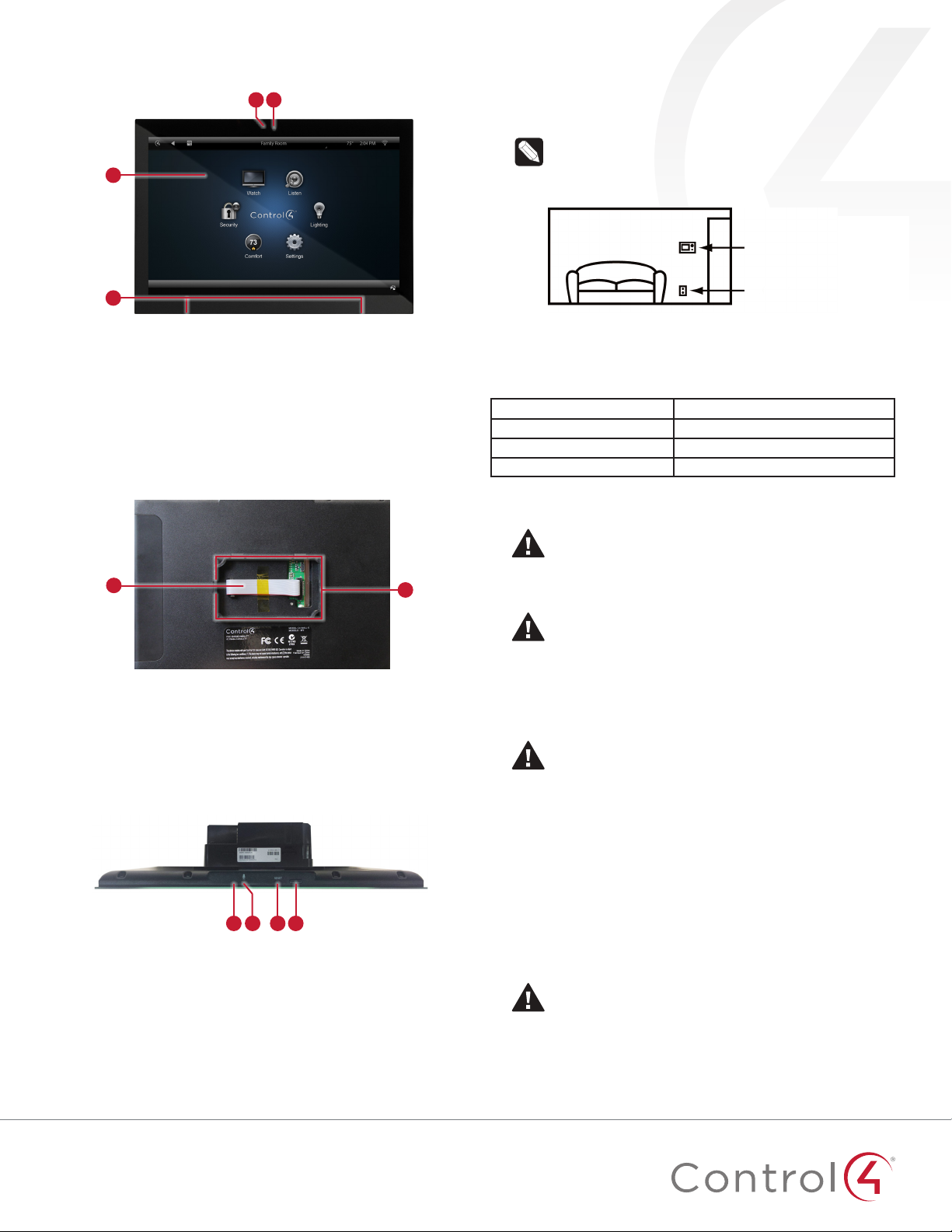
Specications and requirements
Specications
Model Numbers C4-WALL7-BL, C4-WALL7-WH, C4-WALL10-BL,
C4-WALL10-WH
Screen Resolution: 1280 × 800
Camera: 720p
Network
Ethernet or WiFi (802.11b/g/n [2.4 GHz])
Security: WEP, WPA/WPA2 PSK, 801.1x EAP, PEAP
Notes: (1) Intercom usage. 802.11b is not
recommended for Video Intercom. (2) Wireless-N
is recommended for Video Intercom. Even with
Wireless-N, broadcasting to several devices will
degrade Video Intercom response time and images.
Broadcasting to additional devices will further
degrade performance. See “Wireless Network
Limitations.”
Power supply PoE (IEEE802.3af) 13 W peak
100-240VAC, 50/60 Hz
Operating temperature 32 ~ 104˚F (0˚ ~ 40˚C)
Storage temperature 4 ~ 158˚F (-20˚ ~ 70˚C)
Dimensions (W ×H ×D)
7" model: 6.9" ×5.0" ×0.53" (175 ×127 ×13 mm)
10" model: 9.4" ×6.5" ×0.53" (239 × 165 ×13 mm)
Wall box: 2.7"×4.1"×2.4"(68 ×104 ×61 mm)
Power box: 2.8"×4.5"×1.8"(71 ×114 ×46 mm)
Weight (with mid-box) 7"model: 0.9 lbs. (0.41 kg)
10"model: 1.5 lbs. (0.68 kg)
Shipping Weight 7"model: 1.5 lbs (0.68 kg)
10"model: 2.1 lbs (0.95 kg)
Requirements
• A controller fully installed and congured with Control4
OS 2.7.0 or later.
• Control4 7"or 10"In-Wall Touchscreen custom wall box
installed. See “Accessories.”
• If using Ethernet with PoE power:
• Ethernet network installed and available that includes a
gateway/router/switch
• Control4 PoE Injector (model #AC-POE1-B) or another
third-party PoE Injector or switch (UL/ANSI certied).
• Two Ethernet CAT5/6 cables: (1) one that runs from the
Ethernet gateway/router/switch to the PoE Injector/switch
and (2) one that runs from the PoE Injector/switch to the
Ethernet connection in the touchscreen’s wall box.
• If using Ethernet with AC power:
• Ethernet network installed and available that includes a
gateway/router/switch
• Access to in-wall AC power (neutral connection required)
• One Ethernet CAT5/6 cable that runs from the Ethernet
gateway/router/switch to the touchscreen
• A 14-gauge electrical wire long enough to pull between
the touchscreen and the power source
• If using wireless with AC power:
• Wireless network (WiFi 802.11b/g/n) installed and
available with a wireless access point (WAP). Security can
be WEP, WPA/WPA2 PSK, 801.1x EAP, PEAP.
• Access to in-wall AC power (neutral connection required)
• A 14-gauge electrical wire long enough to pull between
the touchscreen and the power source

3
Front view
Figure 1: Front view
C
BA
D
A LED—Indicates when the camera is on.
B Camera—For video intercom calls.
C Display—7"or 10"diagonal, capacitive touchscreen with
1280 ×800 resolution.
D Speakers—Provide stereo audio.
Back view
Figure 2: Back view
AB
A Ribbon cable-Provides data and power connection to the
touchscreen from the power box.
B Mounting ring—Fits into the power box.
Top view
Figure 3: Top view (with power box attached)
A C DB
A Unlabeled pinhole button—Use this pinhole and the RESET
hole to reset the touchscreen to factory defaults. See the
Troubleshooting section for more details
B Microphone—Records audio.
C RESET pinhole button—Use this pinhole to power cycle
the touch screen or as part of a factory reset. See the
Troubleshooting section for more details
D Power button—Press to turn off the touchscreen, or press and
hold to reboot.
Touchscreen placement
Place the touchscreen in a convenient location at eye level,
typically near the entrance of the room, approximately 57 to 61
inches (145 cm to 155 cm) from the oor (Figure 3).
Note: Consider the camera on the panel and the height
of the people in the home who will use the camera for
Video Intercom.
Figure 3: Touchscreen placement
LED indicator
The LED on the touchscreen indicates the camera status of the
camera and booting information as described in the next table.
Camera/LED color state Touchscreen status
Off Camera is off
Green Camera is on
Green (blinking slowly) Touchscreen is booting
Installation
Warning! Before installing the touchscreen, switch off
the circuit breaker or remove the fuse from the fuse box.
AVERTISSEMENT ! Pour l’endroit où vous installez
l’écran tactile, coupez le disjoncteur ou enlevez le fusible
de la boîte de fusible.
Important! Before you can complete the instructions
below, you must have a 7"or 10"Touchscreen wall box
installed according to the documentation provided in
the wall box kit. See “Accessories” for details.
Important ! En coupant l’ouverture pour la boîte de
mur, ne coupez pas l’ouverture trop grande. Soyez
conservateur et agrandissez-avec précaution la comme
nécessaire. Voyez que <<Accessories>>.
Important! When cutting the opening for the wall box,
do not cut the opening too large. Be conservative and
cautiously enlarge it as needed.
Important ! En coupant l’ouverture pour la boîte de
mur, ne coupez pas l’ouverture trop grande. Soyez
conservateur et agrandissez-avec précaution la comme
nécessaire.
Power and network installation options
This device uses an Ethernet or WiFi network connection, and
can be powered using PoE or AC power.
Choose one of the following options to install the power and
network communication.
Caution! Do not attempt to use PoE and AC power at
the same time. Choose only one power option.
ATTENTION ! Ne pas tenter d’utiliser PoE et AC en
même temps. Choisir une seule option d’alimentation.
Touchscreen
AC power
(unless using PoE)

4
Option 1: Ethernet connection with PoE
PoE supplies DC power on the Ethernet cable using a PoE
Injector (model #AC-POE1-B) or a third-party PoE solution to
provide the touchscreen with power and a network connection.
The touchscreen works with the Control4 PoE Injector or a third-
party PoE Injector.
To set up your PoE and Ethernet connection with a PoE Injector:
1 Attach the PoE Injector according to the instructions in your
PoE’s installation guide if provided. Control4 PoE Injector
instructions are provided later in this document.
2 Pull the Ethernet cable from that location to where you want
to install the touchscreen.
Figure 4: Ethernet with PoE—Requires Ethernet connection to PoE
injector
Option 2: Ethernet connection with AC
The Ethernet is connected directly to the switch (Figure 5). This
power connection requires both neutral and hot connections.
Figure 5: Ethernet—Requires a connection to Ethernet and AC power
Option 3: WiFi connection with AC
Place the touchscreen above a power source, for example, an
outlet. Ensure that you have WiFi in the home (Figure 6).
Notes: (1) Video Intercom. Although this device
supports 802.11b/g/n, 802.11 b is not recommended for
Video Intercom use. (2) We recommend Wireless-N for
Video Intercom. See the Composer Pro User Guide for
details about the touchscreen’s properties.
Wireless Network Limitations: Many WiFi Access Points
handle Multicasts (WiFi simultaneously sent to multiple
devices, for example, when the touchscreen broadcasts
video to all stations) by slowing down transmission
speed to the 1 Mb basic rate. This can cause overall WiFi
congestion in the WiFi network during the broadcast.
Video Intercom response times and images may
degrade at each device.
If a home requires a large number of WiFi Video
Intercom devices, ensure that you have a robust WiFi
network (possibly consisting of multiple access points).
Figure 6: WiFi—Requires AC Power and WAP
Power installation
Prepare the plastic power box for installation into the wall box by
inserting either the Ethernet cable or the AC power cable into the
power box, and then follow the instructions.
Connecting PoE
Connect the PoE injector to power and the network, and then
connect it to the power box.
To install a Control4 PoE injector:
1 Connect the Control4 PoE injector to an AC outlet using the
power cord.
2 Connect one of the RJ-45 LAN ports on the gateway/router/
switch to the PoE Injector’s LAN port using CAT5/6 Ethernet
cable.
3 Connect the PoE Injector’s PWR LAN-OUT port to the RJ-45
Ethernet cable that will be connected to the touchscreen’s
power box.
4 Pull the Ethernet cable through the top left hole of the wall
box, then plug it into the Ethernet jack on the top back of
the power box (Figure 7).

5
Figure 7: Insert Ethernet cable into power box
5 Go to “Attach the power box and touchscreen” below.
Connecting standard Ethernet
To connect to a wired network:
1 Pull the in-wall Ethernet cable through the top left hole of
the wall box, then plug it into the Ethernet jack on the top
back of the power box (Figure 8).
Figure 8: Insert Ethernet cable into power box
2 Go to “Attach the power box and touchscreen” below.
Connecting AC power
The steps below represent a typical U.S. installation.
1 Connect the wires to the AC power source for the
touchscreen according to national and local electrical codes.
Installation may require alternative wires and the use of a
terminal block.
2 Thread the power cable through the upper back hole of the
wall box to the terminal block (Figure 7).
3 Strip the black and white power wire ends to 1/4"as
necessary. Using a at-head screwdriver, loosen the screws
on the power box’s terminal block and connect the power
wires to each terminal (Figure 9).
Figure 9: Connect AC power
4 Cap the ground wire from the wall if you are using a plastic
wall box. Attach the ground wire to the wall box if using a
metal wall box.
Attach foam pads (optional)
Four foam pads are included to help stabilize the touchscreen
against the wall. Installation is not required.
To install the foam pads:
1 Peel off the adhesive backing.
2 Place onto the back of the touchscreen near the corners,
spaced about 1.25” (30 mm) from the edges.
Figure 10: Foam pad placement
~1.25"
(~30 mm)
Neutral (N)
Line (L)

6
Attach the power box and touchscreen
To attach the power box and touchscreen:
1 Align and bend the wires carefully to t them inside the wall
box.
2 Align slide the power box into the wall box, then secure the
power box to the wall box using the two screws provided.
Figure 11: Secure power box to wall box
Note: Overtightening the power box screws can warp
the box and make it difcult to attach the touchscreen.
3 Straighten out the ribbon cable taped to the back of the
touchscreen, then plug it into the ribbon cable port in the
power box. To make sure it’s securely connected, press it into
the port until the two locking tabs close onto the connector.
Figure 12: Attach ribbon cable to the power box
4 For easiest installation, angle the top of the touchscreen
toward the wall, insert the top tabs of the mounting ring into
the power box, then press the bottom of the touchscreen
into place.
Figure 13: Attach the touchscreen top rst
Conguration
Congure the touchscreen for wireless (optional)
To congure the touchscreen for wireless:
1 After initialization, tap Network. The network conguration
page opens.
2 Under Wi-Fi, tap or slide OFF/ON to enable WiFi, then tap
the Wi-Fi eld to open a list of available networks.
3 Tap the network name you want to connect to.
4 Tap the Password eld, then use the on-screen keyboard to
type the password (if required).
Note: If you need to enter a static IP address, follow the
instructions under “To set a wireless static IP address”
below before proceeding.
5 Tap Connect.
If you don’t see the network you want:
1 Tap +, then tap the Network SSID eld and type the SSID
(name) of the network by using the on-screen keyboard.
2 Tap the Security eld, then select the type of security to use.
3 Tap the Password eld, then use the on-screen keyboard to
type the password (if required).
Note: If you need to enter a static IP address, follow the
instructions under “To set a wireless static IP address”
below before proceeding.
4 Tap Save. The new network is added to the bottom of the
network list.
To set a wireless static IP address:
1 Scroll down and tap Show advanced options.
2 Tap IP settings, then tap Static.
3 Select each box one at a time and use the on-screen
keyboard to type the:
• IP address
• Gateway
• Network prex length
• DNS 1 (preferred)
• DNS 2 (alternate)
Congure the touchscreen for Ethernet
If you want to use DHCP (default) for your Ethernet connection,
no further setup is required.
To congure a static IP address for Ethernet:
1 After initialization, tap Network. The network conguration
page opens.
2 Tap Ethernet. The Ethernet settings screen opens.
3 Tap Static IP Settings, then tap Use static IP.
4 Select each box one at a time and use the on-screen
keyboard to type the IP Address, Gateway, Netmask, DNS 1
(preferred), and DNS 2 (alternate).
5 Tap SAVE when nished.

7
Add and congure in Composer Pro
After the touchscreen is installed and appears on the home
network, use Composer Pro to add it to the Control4 system and
congure it.
Use the Composer Pro System Design and Connections views to
add and congure this device.
To add and congure a T3 touchscreen to a project:
1 Add the T3-T7 or T3-T10 In-Wall Touchscreen driver to your
project.
2 To congure the properties, click System Design.
3 In the project tree, select the T3 7"or T3 10"In-Wall Touch
Screen.
4 View and change the properties in the Properties pane as
needed.
Properties include:
• Network Connection—Reports the touchscreen’s current
network connection type.
• Back Light—Use the arrows or type numbers to set the
light level, then click Set.
Advanced properties include:
• Enable Camera—Allows you to enable or disable the
camera.
Intercom (nested under the touchscreen) properties:
• Appearance—Select to hide the touchscreen from
appearing in Navigators as an available device.
• Behavior—Select the modes you want this touchscreen to
support.
• Audio Control—Select the volume of individual audio
settings.
• Sip Information—Information for integrating the
touchscreen into your SIP/VoIP system.
• Custom Buttons—Select to enable and label the two
available custom buttons.
• Alternate Camera—Select to use an external camera for
the video associated with the touchscreen, for example, a
security camera mounted to the side of the entrance and
pointing at the door.
Troubleshooting
Boot up time
When the device is booting up, it may take 30 seconds or longer
before the Green LED turns on. When it turns on, it blinks slowly
for a time and then turns off. After that, you’ll see an image on
the touchscreen.
Unresponsive screen
If the camera’s LED blinks on and off for more than 30 seconds,
the device may need to be power cycled. If power cycling doesn’t
solve the problem, the touchscreen may need to be restored to
factory defaults.
To power cycle the touchscreen:
1 Press and hold the (power) button for several seconds
until the touchscreen turns off.
2 Press and release the (power) button again to turn on.
- OR -
1 Use a straightened paper clip to press and release the
RESET pinhole button.
To restore to factory defaults:
1 On the touchscreen’s main screen, tap Settings, System Info,
then Factory data reset.
- OR -
If the touchscreen has not yet been congured, tap About,
then Factory data reset.
- OR -
a To reset without using the display screen, insert a
straightened paper clip into the pinhole to the left of the
microphone on top of the touchscreen.
b Then press and hold it while pressing and releasing the
RESET pinhole. Hold the pinhole to the left of the
microphone until the icon below appears on the display
then release the pinhole.
c A message appears, indicating that data is being erased.

control4.com | 888.400.4070
Removing the touchscreen from the wall
To remove the touchscreen:
1 Hold the removal tool at against the wall, centered directly
beneath the touchscreen, then slide it upward between the
wall and touchscreen.
Figure 14: Slide the removal tool behind the touchscreen
2 While pressing the tool up as far as it will go, carefully pull
the touchscreen away from the wall.
Additional resources
The following resources are available for more support.
• Control4 Tech Community
• Control4 Technical Support
• Composer documentation in online help or PDF formats,
available on the Dealer Portal under Resources
Warranty and legal notices
Find details of this product’s 2-Year Limited Warranty at
snapone.com/legal
, or request a paper copy from Customer
Service at (866) 424-4489. Find other legal resources, such as
regulatory notices and patent information, at
snapone.com/legal
.
More help
For the latest version of this document, open this URL or scan the
QR code on a device that can view PDFs.
200-00387-G
2022-04-29 DH
Copyright ©2022, Snap One, LLC. All rights reserved. Snap One and its respective logos are registered trademarks or trademarks of Snap One, LLC (formerly
known as Wirepath Home Systems, LLC), in the United States and/or other countries. Control4, SnapAV, and Wirepath are also registered trademarks or
trademarks of Snap One, LLC. Other names and brands may be claimed as the property of their respective owners. Other names and brands may be claimed
as the property of their respective owners. Snap One makes no claim that the information contained herein covers all installation scenarios and contingencies,
or product use risks. Information within this specication subject to change without notice.
G
LATEST VERSION OF THIS DOCUMENT
ctrl4.co/iw-ig
Other manuals for T3 Series
2
This manual suits for next models
6
Table of contents
Other Contro l4 Touchscreen manuals

Contro l4
Contro l4 C4-FP C Series User manual

Contro l4
Contro l4 T4 Series User manual

Contro l4
Contro l4 C4-TW7C0-BL User manual

Contro l4
Contro l4 C4-TSMC7-EN-BL User manual

Contro l4
Contro l4 T4 Series User manual

Contro l4
Contro l4 T4 Series User manual

Contro l4
Contro l4 T3 Series User manual

Contro l4
Contro l4 T4 Series User manual