manuals.online logo
Brands
  1. Home
  2. •
  3. Brands
  4. •
  5. Controlli
  6. •
  7. Controllers
  8. •
  9. Controlli MVB2 Series User manual

Controlli MVB2 Series User manual

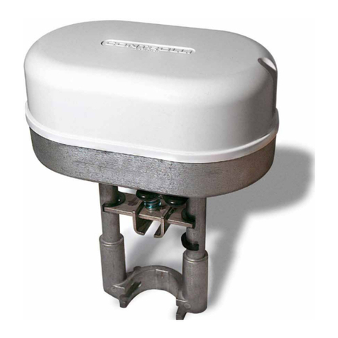
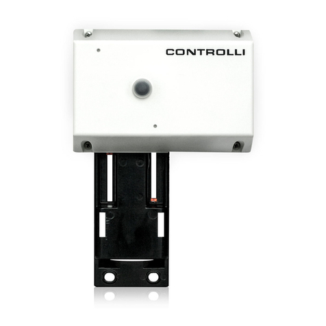
Valve Actuators MVB
Rev. l 11/06 1 DIM001E
CONTROLLI
16010 SANT’OLCESE Genova - Italy
Tel.: +39 01073061 Fax: +39 0107306870/871
E-mail: [email protected] Web: www.controlli.org
ISO 9000
CONTROLLI
MOUNTING INSTRUCTIONS
FOR MVB 36-52-56 ONLY
FIG. 2
N3133
The actuator can be mounted in any position for applica-
tions in which the fluid temperature is not higher than 120
°C, otherwise it should be mounted in horizontal position.
It is necessary to leave 10 cm. above and beside it, so as
to operate on the internal parts, on the terminal board for
the electric connections and for assembling-disassembling
operations.
2. VSB-VMB/VSBF-VMBF/VSBPM-VMBPM/
VSBPMF-VMBPMF VALVES ASSEMBLY
(Fig.1)
•Pull and turn counter-clockwise the manual knob 1until
the joint reaches the upper mechanical stop.
•For VSB-VMB/VSBF-VMBF: Pull out the knob 1 and
rotate clockwise (max 1/4 turn) until it enters the first
rest position.
•For VMBPM-VSBPM/VMBPMF-VSBPMF: Pull out the
knob 1and rotate clockwise (max 1/2 turn) until it en-
ters the second rest position.
•Make sure the plug reaches upper seat by lifting the
valve stem.
•If a spacer for high temperatures is needed, insert the
MVBHT accessory 4onto the valve neck.
•Position the actuator on the valve interposing the ring
nut 3between the stem and the mounting bracket.
•Rotate the actuator until the bracket rests on the valve
body.
•Tighten the ring nut 3 using the supplied spanner.
•Keeping the valve stem steady, force counter-clockwise
the lower hexagonal part of joint 2(which acts as a
locknut) until it detaches.
•Then screw clockwise the part which has been detached
so as to tighten it on the rest of the joint, thus blocking
the valve stem.
•Remove the back cover (opposite the knob).
•For MVB52/56 only, make sure that jumper SW2 is in A
position (Fig. 2).
•Supply the actuator between L1 and L2 terminals with Y
terminal disconnected.
•Wait the actuator to reach the lower stroke end.
•Connect the positive of the voltmeter to S2 terminal and
the negative to M.
•Rotate P1 trimmer until the voltmeter indicates 0 V.
FIG. 1
N4161
3. ACTUATOR STROKE CALIBRATION ONLY
FOR STROKES DIFFERENT FROM 16.5 mm
1. INSTALLATION
Automatic control systems for:
air conditioning/heating/industrial thermal process
CONTROLLI
Rev. l 11/06 2 DIM001E
4. ELECTRICAL CONNECTIONS
Perform the electrical connections according to the following diagrams and in compliance with existing rules.
(1) With voltage between N (Common) and Y1 (phase from controller contact): the actuator joint moves upwards. With
voltage between N and Y2 the joint moves downwards. Without voltage the actuator remains in the position gained.
(2) For MVB36: connect the controller potentiometer cursor (165 Ω) to Y terminal, one end to M and the other to V+
terminal.
(3) When SW2 jumper is in C position (See Fig. 2) and signal increases, the joint moves downwards.
(4) Connect the indicator with input current to S3 (or S2) and S1 terminals. Connect the indicator with input voltage to S3
(or S2) and M terminals. The extreme left voltage (current) value corresponds to joint up.
TERMINAL BOARD
- MVB5.
- MVB36 LEGEND
L1 Phase
L2=M=Common
MCommon
V+ 15 V- output (2)
YControl signal (3)
S3 10...0V- or 200...0 µA
S2 0...10V- or 0...200 µA(4)
S1 Analogue common
24 V~ +10%
power supply
(*) Internally connected
TERMINAL BOARD
- MVB2. (230 V~)
- MVB46 (24 V~) LEGEND
Y1 Joint up
NCommon Control (1)
Y2 Joint down
N3009
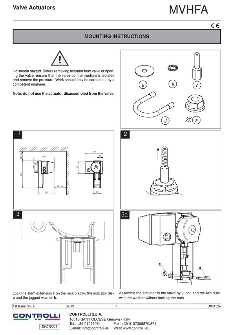
NOTE: For MVB actuators are available the following accessories: MVBPA2 (card with 1Kohm auxiliary
potentiometer), D36 (micro auxiliary contact with adjustable cam), MVBHT (spacer for high tem-
peratures), 244 (stem heater), MVBD (AUT/MAN microswitch - Only factory-mounted) and MVBC
(Rainproof protection).
For further details make reference to the relevant mounting instructions (DIM004 and DIM023 only for
244).
P.C. board with an auxiliary potentiometer (MVBPA2) available only on request when ordering an
actuator and factory-mounted.
The performances stated on this sheet can be modified without any prior notice due to design improvements.

This manual suits for next models

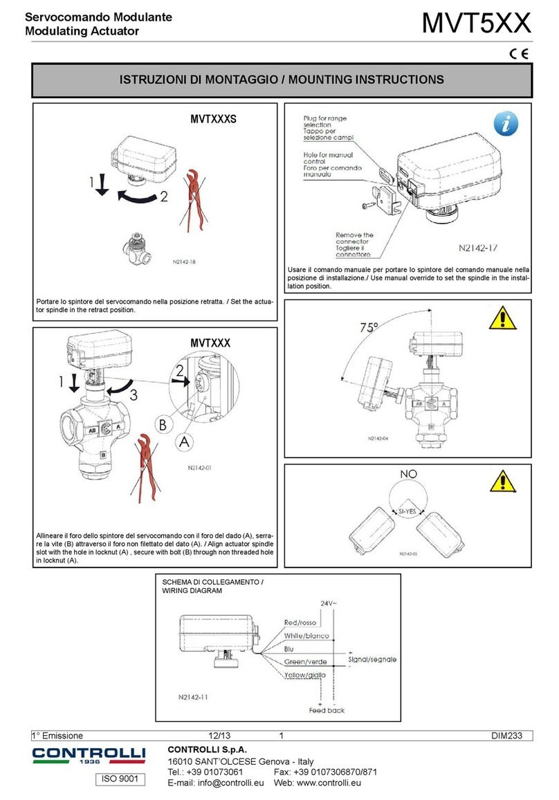
5

Other Controlli Controllers manuals

Controlli MVE5 Series User manual

Controlli

Controlli MVE5 Series User manual

Controlli MVHFA User manual

Controlli

Controlli MVHFA User manual

Controlli MVT5 Series User manual

Controlli

Controlli MVT5 Series User manual

Controlli MVE2R Series User manual

Controlli

Controlli MVE2R Series User manual

Controlli MVH56EA User manual

Controlli

Controlli MVH56EA User manual

Controlli DuraDrive MX40-7 User manual

Controlli

Controlli DuraDrive MX40-7 User manual

Controlli MVE2 R-65 Series User manual

Controlli

Controlli MVE2 R-65 Series User manual

Controlli MVT5 Series User manual

Controlli

Controlli MVT5 Series User manual

Controlli MVH56EX User manual

Controlli

Controlli MVH56EX User manual

Controlli Energon User manual

Controlli

Controlli Energon User manual

Controlli MVT203 User manual

Controlli

Controlli MVT203 User manual

Controlli Energon NR9001 User manual

Controlli

Controlli Energon NR9001 User manual

Controlli MVE2 Series User manual

Controlli

Controlli MVE2 Series User manual

Controlli MVH56E User manual

Controlli

Controlli MVH56E User manual

Controlli MVH User manual

Controlli

Controlli MVH User manual

Controlli MVE5 R Series User manual

Controlli

Controlli MVE5 R Series User manual

Controlli MVH26 User manual

Controlli

Controlli MVH26 User manual

Controlli MVH56E User manual

Controlli

Controlli MVH56E User manual

Controlli NR9000 User manual

Controlli

Controlli NR9000 User manual

Controlli MVC503R-MB User manual

Controlli

Controlli MVC503R-MB User manual

Controlli NR9003 User manual

Controlli

Controlli NR9003 User manual

Controlli MVE2-65 Series Owner's manual

Controlli

Controlli MVE2-65 Series Owner's manual

Controlli MVE2 R Series User manual

Controlli

Controlli MVE2 R Series User manual

Controlli MVT5 Series User manual

Controlli

Controlli MVT5 Series User manual

Popular Controllers manuals by other brands

Varian Turbo-V 150 PCB instruction manual

Varian

Varian Turbo-V 150 PCB instruction manual

Powered Aire AERO CONNECT Operating and maintenance manual

Powered Aire

Powered Aire AERO CONNECT Operating and maintenance manual

Toro TEMPUS 53828 user guide

Toro

Toro TEMPUS 53828 user guide

SDMO Nexys 2 instruction manual

SDMO

SDMO Nexys 2 instruction manual

Linkam Scientific Instruments RH95 user guide

Linkam Scientific Instruments

Linkam Scientific Instruments RH95 user guide

Naturela NPBC-V3C-1 Technical manual

Naturela

Naturela NPBC-V3C-1 Technical manual

FASAR ELETTRONICA FE1055 quick start guide

FASAR ELETTRONICA

FASAR ELETTRONICA FE1055 quick start guide

Danfoss FH-WC installation guide

Danfoss

Danfoss FH-WC installation guide

ABB MS116 installation instructions

ABB

ABB MS116 installation instructions

Quirky Link Hub user guide

Quirky

Quirky Link Hub user guide

Maxon PARVALUX SC 50/15 Hardware reference

Maxon

Maxon PARVALUX SC 50/15 Hardware reference

Krüger & Matz KM0770 owner's manual

Krüger & Matz

Krüger & Matz KM0770 owner's manual

ETC F-Drive W1 Series installation manual

ETC

ETC F-Drive W1 Series installation manual

Dungs DGAU. 09/2 Operating and assembly instructions

Dungs

Dungs DGAU. 09/2 Operating and assembly instructions

Merlin 58184 Owner's manual & safety instructions

Merlin

Merlin 58184 Owner's manual & safety instructions

Kentek ACM-AUTO Operation manual

Kentek

Kentek ACM-AUTO Operation manual

RLE Technologies LD1500 user guide

RLE Technologies

RLE Technologies LD1500 user guide

Votronic VPC Terra Installation and operating manual

Votronic

Votronic VPC Terra Installation and operating manual

manuals.online logo
manuals.online logoBrands
  • About & Mission
  • Contact us
  • Privacy Policy
  • Terms and Conditions

Copyright 2025 Manuals.Online. All Rights Reserved.