manuals.online logo
Brands
  1. Home
  2. •
  3. Brands
  4. •
  5. Cooper Lighting
  6. •
  7. Lighting Equipment
  8. •
  9. Cooper Lighting HALO LAZER LZR204 User manual

Cooper Lighting HALO LAZER LZR204 User manual

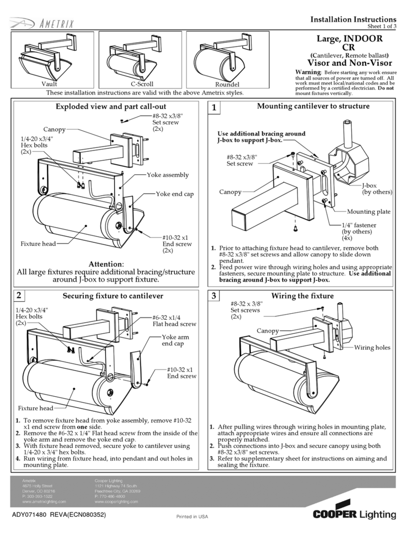
Installation Instructions for
LZR204/LZR 205
Conduit Adapter Feed & Conduit
Continuation Feed
NOTE:For use with LZR 100 series Track system
only. Ground contact must be on the same side as the
Polarity Groove of the track. Electrical Ratings:
120V, 60HZ, 20A
IF USED AS A POWER FEED POINT
STEP 1: nsert ends of connector into ends of track
(Polarity Arrow) must line up with Polarity Groove of
track). Secure to track by tightening lock screw at the
tip of connector until snug. DO NOT OVER
TIGHTEN, this may distort track.
INSTRUCTIONS
POLAR TY GROOVE
GORGE DE POLAR TE
RANURA DE POLAR DAD
POLAR TY GROOVE
GORGE DE POLAR TE
RANURA DE POLAR DAD
POLAR TY ARROW
FLECHE DE POLAR TE
FLECHA DE POLAR DAD
POLAR TY ARROW
FLECHE DE POLAR TE
FLECHA DE POLAR DAD
SPACER
ENTRETO SE
ESPAC ADOR
SPEED NUT
ECROU-TOLE
TUERCA DE AJUSTE RAP DO
Instrucciones de instalación para la
Alimentación eléctrica del adaptador
del conductor y la Alimentación eléc-
trica de continuación del conductor
LZR204/LZR205
NOTA: Para su utilización con el sistema de Riel de
la serie LZR 100 solamente. El contacto a tierra tiene
que estar en el mismo lado que la Ranura de polari-
dad del riel. Capacidades nominales eléctricas: 120V,
60Hz, 20A.
INSTRUCCIONES
SI SE UTILIZA COMO UN PUNTO DE ALIMENTACION
ELECTRICA
PASO 1: nserte los extremos del conector dentro de
los extremos del riel. (La Flecha de polaridad tiene
que quedar alineada con la Ranura de polaridad del
riel). Asegure al riel mediante el apriete del tornillo de
seguridad en la punta del conector hasta que éste
quede a ras. NO APRIETE EN EXCESO, esto puede
deformar el riel.
Instructions d'installation des alimenta-
tions avec adaptateur et raccord de
conduit pour LZR 204/LZR 205
REMARQUE : À n’utiliser qu’avec le système de rails
série LZR 100. Les contacts de terre et la gorge de
polarité du rail doivent être du même côté.
Alimentation électrique : 120 V, 60 Hz, 20 A
INSTRUCTIONS
EN CAS D'UTILISATION COMME POINT D'ALIMEN-
TATION ÉLECTRIQUE
ÉTAPE 1 : ntroduire les extrémités du connecteur
dans les extrémités du rail (la flèche de polarité et la
gorge de polarité doivent être alignées). Fixer le rail en
serrant la vis de blocage à l'extrémité du connecteur.
NE PAS SERRER TROP FORT afin de ne pas
déformer le rail.
INSTALLATION INSTRUCTIONS
IMPORTANT SAFETY
INSTRUCTIONS
1. Read all of these installation instructions before
installing the track system.
2. Save These nstructions
and refer to them when additions or changes in the
track configuration are made.
3. Disconnect electrical power before adding to or
changing the configuration of the track.
4. For use with LZR100 Series track systems only.
5. Electrical ratings: 120V, 60Hz, 20A
INSTRUCTIONS D’ INSTALLATION
IMPORTANTES CONSIGNES DE
SÉCURITÉ
1. Pour l’installation ou l’utilisation du présent système
sur rail, veullez prendre des mesures de sécurité de
base, y compris les mesures suivantes.
2. Conserver ces instructions
et s’y reporter en cas d’ajouts ou de changements
au profil du système sur rail.
3. Couper le courant électrique avant de faire des
ajouts ou des changements au profil du rail.
4. Seulement pour systèmes de rails série LZR100.
5. Alimentation electrique: 120V, 60Hz, 20A
INSTRUCCIONES DE INSTALACIÓN
MEDIDAS IMPORTANTES DE
SEGURIDAD
1. Antes de conectar el sistema de rieles lea las
instrucciones para instalación
2. Guarde estas instrucciones
y sigalas cada vez que se hagan adiciones o cam-
bios en la configuracion del sistema.
3. Desconecte el suministro eléctrico antes de hacer
adiciones o canbios en la configuración del
sistema.
4. Para ser utilizado solamente con los sistemas de
riel de la serie LZR 100.
5. Capacidades nominales eléctricas: 120V, 60Hz, 20A
Cooper Lighting
Customer First Center • 1121 Highway 74 South • Peachtree City, GA 30269 701160
PASO 2: Quite la cubierta. Si se utiliza con el conduc-
tor montado en la superficie, una la conexión de sum-
inistro (entregada por terceros) a través del agujero
roscado en la placa posterior. La alimentación del
adaptador del conductor también puede ser utilizada
con conductor de entrada superior. Extraiga el disco
removible del conductor. Una la conexión de sumin-
istro (entregada por terceros) instalando primero el
espaciador de rosca (que se entrega) y luego insta-
lando a través del agujero en la placa posterior y ase-
gure con la tuerca de acción rápida (entregada por
terceros). NOTA: Hay que utilizar el espaciador para
asegurar un montaje apropiado.
PASO 3: Pele los cables de suministro eléctrico a la
longitud apropiada utilizando el calibrador en la parte
interior del conector (1/2" de longitud nominal de
peladura). Tire de los cables de suministro hacia el
interior del conector. Conecte el cable de suministro
eléctrico (de color) al tornillo marcado como LINE
(L NEA) y el cable neutral (blanco) al tornillo marcado
como NEUT (NEUTRO). Si hay un cable de tierra
disponible, éste debe ser conectado al tornillo marca-
do como GND (T ERRA).
PASO 4: Quite cuidadosamente el área precortada en
la cubierta y limpie el borde con una cuchilla de uso
general. Vuelva a colocar la cubierta en su lugar.
NOTA: Si se utiliza con disco removible de ali-
mentación superior opcional. NO QUITE EL AREA
PRECORTADA.
SI SE UTILIZA COMO UNA ALIMENTACION DE
CONTINUACION DEL CONDUCTOR
La alimentación de continuación del conductor se uti-
liza más comúnmente para continuar un tramo del riel
con el conductor montado en la superficie que haya
sido obstruido. El juego se suministra con una ali-
mentación del adaptador del conductor de izquierda y
otra de derecha. Siga las instrucciones de insta-
lación que se dan más arriba, utilizando las ali-
mentaciones de conductor de la izquierda y de la
derecha como se muestran en la ilustración.
STEP 2: Remove cover. f used with surface mount-
ed conduit, attach supply fitting (supplied
by others) through threaded hole in back plate. The
conduit adaptor feed may also be used with top entry
conduit. Remove conduit knockout. Attach supply fit-
ting (supplied by others) by first threading spacer
(supplied) then installing through hole in back plate
and secure with speed nut (supplied by others).
NOTE: Spacer MUST be used to insure proper
assembly.
STEP 3: Strip supply wires to proper length using
gauge on inside of connector (1/2" nominal strip
length). Pull supply wires into connector. Connect
power supply wire (colored) to screw marked LINE
and neutral wire (white) to screw marked (NEUT). f a
ground wire is available it should be connected to the
screw marked GND.
STEP 4: Carefully remove tear out area in cover
and clean up edge with utility knife. Replace cover.
NOTE: if used with optional top feed knock out. DO
NOT REMOVE TEAR OUT AREA.
IF USED AS A CONDUIT CONTINUATION FEED
The conduit continuation feed is most commonly used
to continue a run of track with surface mounted con-
duit that has been obstructed. The kit is supplied with
both a left hand and right hand conduit adaptor feed.
Follow installation instructions given above, using
left hand and right hand conduit feeds as shown in
illustration.
ÉTAPE 2 : Enlever le couvercle. En cas d'utilisation
avec un conduit monté en saillie, installer l'applique
d'alimentation électrique (fournie par d'autres) en l'in-
troduisant dans le trou fileté de la plaque arrière.
L'alimentation avec adaptateur de conduit peut égale-
ment être utilisée avec des conduits à entrée par le
haut. Enlever l'entrée défonçable du conduit. Monter
l'applique d'alimentation (fournie par d'autres) en
taraudant d'abord l'entretoise (fournie par d'autres),
puis en introduisant l'applique par le trou de la plaque
arrière et en la fixant au moyen de l'écrou-tôle (fourni
par d'autres). REMARQUE : L'entretoise DOIT être
utilisée afin d'obtenir un assemblage correct.
ÉTAPE 3 : Dénuder les fils d'alimentation sur une
longueur correcte en se référant au gabarit de
dénudage sur la face intérieure du connecteur
(longueur de dénudage nominale de 1/2 po).
ntroduire les fils d'alimentation dans le connecteur.
Connecter le fil d'alimentation (coloré) à la vis mar-
quée LINE et le fil neutre (blanc) à la vis marquée
NEUT. Si un fil de terre est disponible, le connecter à
la vis marquée GND.
ÉTAPE 4 :Enlever soigneusement la pièce recou-
vrant l'ouverture du couvercle et nettoyer le bord au
couteau. Remettre le couvercle en place. REMAR-
QUE : Si l’ouverture défonçable de l’option d’entrée
par le haut est utilisée, ne pas enlever la pièce
recouvrant l'ouverture DU COUVERCLE.
EN CAS D'UTILISATION COMME ALIMENTATION
AVEC RACCORD DE CONDUIT
L’alimentation avec raccord de conduit sert générale-
ment à prolonger un conduit bouché monté en saillie.
Le kit contient une alimentation avec adaptateur de
conduit gauche et droit. Suivre les instructions ci-
dessus, en utilisant les alimentations de conduit
gauche et droit, comme indiqué dans l'illustration.
Cooper Lighting
Customer First Center • 1121 Highway 74 South • Peachtree City, GA 30269
701160

Other Cooper Lighting Lighting Equipment manuals

Cooper Lighting Corelite Continua SQ4 User manual

Cooper Lighting

Cooper Lighting Corelite Continua SQ4 User manual

Cooper Lighting SURE-LITES CX Series User manual

Cooper Lighting

Cooper Lighting SURE-LITES CX Series User manual

Cooper Lighting MT250 User manual

Cooper Lighting

Cooper Lighting MT250 User manual

Cooper Lighting MS185R User manual

Cooper Lighting

Cooper Lighting MS185R User manual

Cooper Lighting Halo L650 User manual

Cooper Lighting

Cooper Lighting Halo L650 User manual

Cooper Lighting IRIS E4RPINSR User manual

Cooper Lighting

Cooper Lighting IRIS E4RPINSR User manual

Cooper Lighting ALL-PRO AL3050LPC Series User manual

Cooper Lighting

Cooper Lighting ALL-PRO AL3050LPC Series User manual

Cooper Lighting ClearCurve Wall Invue User manual

Cooper Lighting

Cooper Lighting ClearCurve Wall Invue User manual

Cooper Lighting ALL-PRO MST18920LES User manual

Cooper Lighting

Cooper Lighting ALL-PRO MST18920LES User manual

Cooper Lighting Sure-Lites LEM User manual

Cooper Lighting

Cooper Lighting Sure-Lites LEM User manual

Cooper Lighting ATLANTIC PLUS User manual

Cooper Lighting

Cooper Lighting ATLANTIC PLUS User manual

Cooper Lighting W35HPC User manual

Cooper Lighting

Cooper Lighting W35HPC User manual

Cooper Lighting PORTFOLIO CD61 Series User manual

Cooper Lighting

Cooper Lighting PORTFOLIO CD61 Series User manual

Cooper Lighting IRIS MH4CFL42E User manual

Cooper Lighting

Cooper Lighting IRIS MH4CFL42E User manual

Cooper Lighting HALO Series User manual

Cooper Lighting

Cooper Lighting HALO Series User manual

Cooper Lighting Combolight Trimmed V90229-1T User manual

Cooper Lighting

Cooper Lighting Combolight Trimmed V90229-1T User manual

Cooper Lighting METALUX HBSPMS User manual

Cooper Lighting

Cooper Lighting METALUX HBSPMS User manual

Cooper Lighting MS80 User manual

Cooper Lighting

Cooper Lighting MS80 User manual

Cooper Lighting MIGHT LIGHT LED130 User manual

Cooper Lighting

Cooper Lighting MIGHT LIGHT LED130 User manual

Cooper Lighting ADH080901 User manual

Cooper Lighting

Cooper Lighting ADH080901 User manual

Cooper Lighting Portfolio LD4A User manual

Cooper Lighting

Cooper Lighting Portfolio LD4A User manual

Cooper Lighting LINEA Series Installation guide

Cooper Lighting

Cooper Lighting LINEA Series Installation guide

Cooper Lighting Night Harrier/NHR User manual

Cooper Lighting

Cooper Lighting Night Harrier/NHR User manual

Cooper Lighting LRM347 Instruction manual

Cooper Lighting

Cooper Lighting LRM347 Instruction manual

Popular Lighting Equipment manuals by other brands

ADJ micro wash wwcw User instructions

ADJ

ADJ micro wash wwcw User instructions

Acuity Brands Lithonia Lighting VAP installation instructions

Acuity Brands

Acuity Brands Lithonia Lighting VAP installation instructions

whi STACKA SBLY-1403.S Product instructions

whi

whi STACKA SBLY-1403.S Product instructions

Greenlite 13W/T8/4B/35K/DE installation guide

Greenlite

Greenlite 13W/T8/4B/35K/DE installation guide

Europalms 83330320 user manual

Europalms

Europalms 83330320 user manual

Paul C. Buff Einstein 640 operating instructions

Paul C. Buff

Paul C. Buff Einstein 640 operating instructions

Federal Signal Corporation SIGNALMASTER SM518A instruction sheet

Federal Signal Corporation

Federal Signal Corporation SIGNALMASTER SM518A instruction sheet

American DJ Reflex LED Pulse User instructions

American DJ

American DJ Reflex LED Pulse User instructions

Pyle PLEDRD27 quick guide

Pyle

Pyle PLEDRD27 quick guide

WAC Lighting HR-3LED-H20A installation instructions

WAC Lighting

WAC Lighting HR-3LED-H20A installation instructions

Ultra-tow 42972 owner's manual

Ultra-tow

Ultra-tow 42972 owner's manual

EuroLite LED ML-56 user manual

EuroLite

EuroLite LED ML-56 user manual

Twinkly Spritzer TWB200STP-WEU Instruction guide

Twinkly

Twinkly Spritzer TWB200STP-WEU Instruction guide

Diamante CHAIN 600 user manual

Diamante

Diamante CHAIN 600 user manual

CowboyStudio Flash40 Setup instructions

CowboyStudio

CowboyStudio Flash40 Setup instructions

Velleman Luxibel CUBIX VDPL302FD user manual

Velleman

Velleman Luxibel CUBIX VDPL302FD user manual

Cameo CLSTROBE1 user manual

Cameo

Cameo CLSTROBE1 user manual

Steelman LED TIREJIM LIGHT instructions

Steelman

Steelman LED TIREJIM LIGHT instructions

manuals.online logo
manuals.online logoBrands
  • About & Mission
  • Contact us
  • Privacy Policy
  • Terms and Conditions

Copyright 2025 Manuals.Online. All Rights Reserved.