Core Health & Fitness Stairmaster HIIT ROWER User manual

OWNER'S
MANUAL
CORE HEALTH & FITNESS
HIIT®ROWER

Page 1
TABLE OF CONTENTS
IMPORTANT SAFETY INSTRUCTIONS................................................................................................................2
PRODUCT DETAILS ........................................................................................................................4
MODEL SPECIFICATIONS ................................................................... 4
ASSEMBLY ........................................................................................................................6
PROCEDURE ................................................................... 7
USING THE HIIT ROWER ......................................................................................................................12
OPERATIONS ......................................................................................................................13
ATTACHING THE MONORAIL ................................................................. 13
DETACHING THE MONORAIL ................................................................. 15
HIIT CONSOLE ......................................................................................................................16
CONSOLE FEATURES ................................................................. 16
CONSOLE PROGRAMS ................................................................. 17
MAINTENANCE MODE ................................................................. 18
MAINTENANCE ......................................................................................................................19
TOOLS ................................................................. 19
MAINTENANCE SCHEDULE ................................................................. 20
BUNGEE INSTALLATION ................................................................. 21
SUPPORT & SERVICE ......................................................................................................................24

Page 2
Before using this product, it is essential to read the ENTIRE Owner’s Manual and ALL
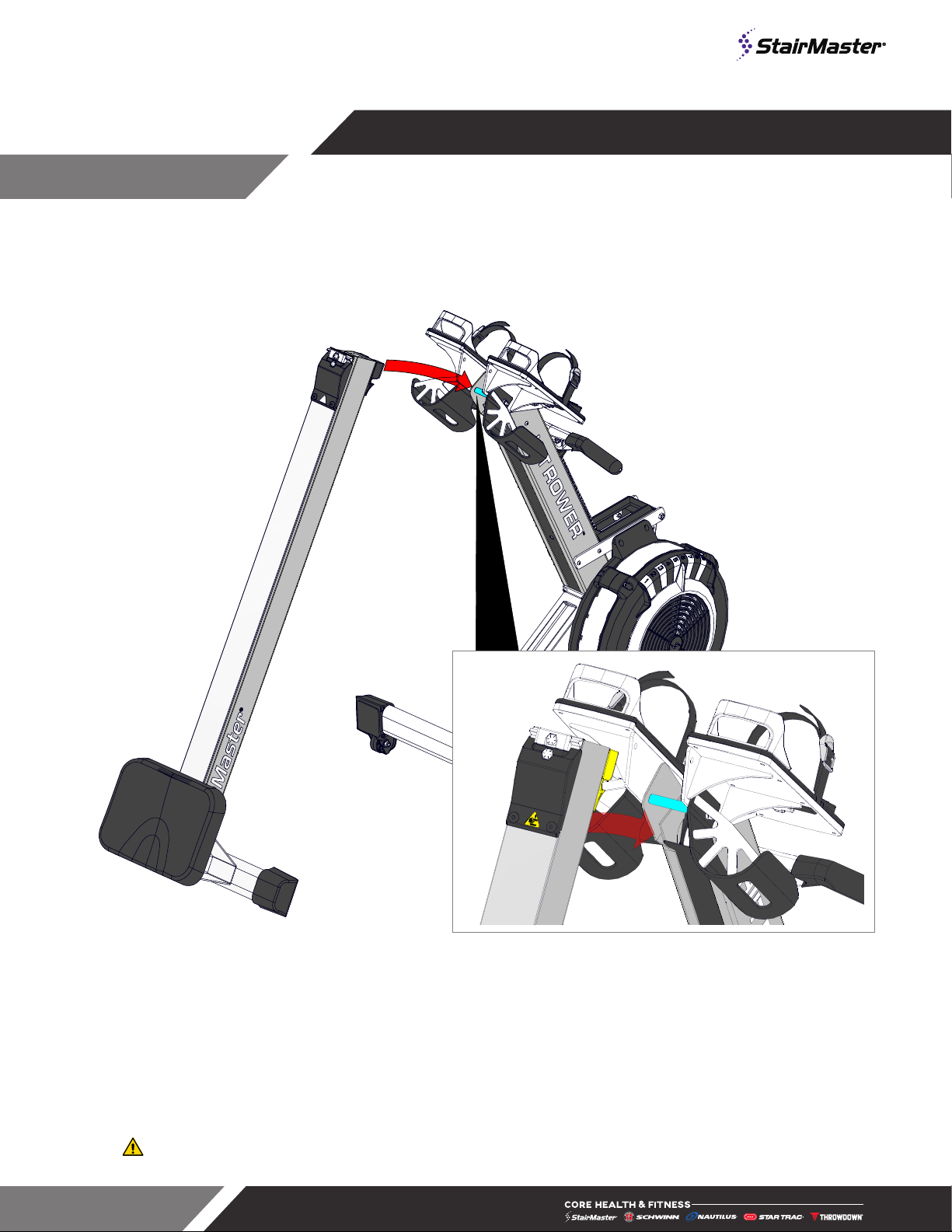
installation instructions. The Owner’s Manual describes equipment assembly and instructs
members on how to use correctly and safely.
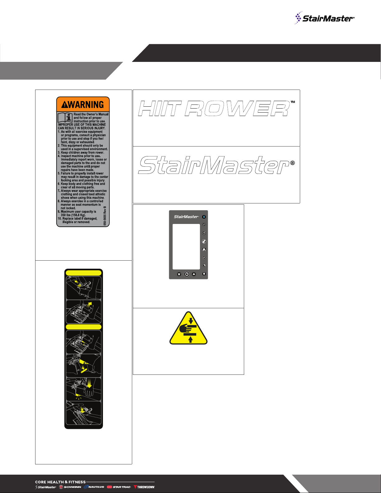
Read all warnings posted on the machine.
Health related injuries may result from incorrect or excessive use of exercise equipment.
Core Health & Fitness strongly recommends you to encourage your members to discuss their
health program or fitness regimen with a health care professional, especially if you or they
have not exercised for several years, are over 35, or have known health conditions.
WARNING!
WARNING: to reduce the risk of serious injury to
persons using this equipment, read and follow all of
these warnings:
24 in (0.6 m)
Fig. 1 Required Clearance
1. Assemble and operate the unit on a solid level
surface. Position the machine with a minimum of
24 inches (0.6 meters) of clearance on one side
to allow for ease of mounting and dismounting.
Leave a minimum of 19.7 inches (0.5 meters)
between two adjacent units. These dimensions
are the recommended minimum distances.
The actual area for access and passage shall be
the responsibility of the facility and should take
into account this training envelope, Americans
with Disabilities Act Accessibility Guidelines
(ADAAG) requirements and any required local
codes or regulations (www.access-board.gov/
ada).
2. Safe and effective use can only be achieved
if the equipment is assembled, maintained
and used properly. Use of this machine with
a worn or weakened part, such as the chain,
sprockets, chain/swivel connector, handle
U-bolt or shock cord, may result in injury to
the user. When in doubt about the condition of
any part, STAIRMASTER strongly advises that
it be replaced immediately. Use only genuine
STAIRMASTER parts. Use of other parts may
result in injury or poor performance of machine.
3. The safety and integrity of this machine can only
be maintained when the equipment is regularly
examined for damage and wear and repaired.
It is the sole responsibility of the owner of this
equipment to ensure that regular maintenance
is performed. Worn or damaged parts must be
replaced immediately or the equipment removed
from service until the repair is made.
4. Do not exceed the maximum allowable weight
limit of:
• 350 lbs. (160 kg.)
5. This machine is not intended to be used by
persons with reduced physical, sensory, or
mental capabilities or lack of experience and
knowledge, unless given instruction and under
the personal supervision concerning use of the
machine by a person responsible for their safety.
6. This equipment it is not suitable for therapeutic
use.
7. Keep children away.
IMPORTANT SAFETY INSTRUCTIONS

Page 3
8. Seat rollers can cause injury. Keep children, pets,
clothes, and fingers away from seat rollers.
9. Do not let handle fly into chain guide.
10. Pull straight back with both hands. Do not row
with one hand only. Abuse of the chain can result
in injury or damage to the equipment.
11. Never twist chain or pull from side to side.
12. Place handle against the chain guide or in handle
hooks before letting go.
13. Ensure all adjustment and locking features are
properly secured before using the equipment.
14. When adjusting the foot straps be sure the straps
are tight and properly restraining your feet to
avoid any injury.
15. Wear proper exercise clothing and athletic shoes
during a workout. Avoid wearing loose clothing.
Tie back long hair and keep towels away from
the moving parts. Face forward at all times and
never attempt to turn around while the machine is
moving.
16. Do not over exert yourself during exercise. Stop
exercising if you feel pain or tightness in your
chest, become short of breath or feel faint. If you
feel pain or experience any abnormal symptoms,
stop exercising and consult your health care
provider.
17. It is the purchaser’s sole responsibility to properly
instruct its end users and supervising personnel
as to the proper operating procedures of all
equipment.
SAVE THESE INSTRUCTIONS

Page 4
MODEL SPECIFICATIONS
Model: 9-4690 HIIT Rower
Unit Weight1Width Length Seat Height Max User Weight
82 lbs
37 kg
26.5 in
68 cm
96 in
244 cm
14 in
35 cm
350 lbs
160 kg
1 Shipping Weight: 90 lbs (41 kg)
This page shows the location of the warning labels and communication stickers placed on the equipment as part of the manufacturing process. It is critical that
owners maintain the integrity and placement of these stickers. If you find any stickers missing or damaged the replacement numbers are shown on the support
site and following pages. See Support and Service to order replacements. Note: Label images on following pages not to scale.
Serial Label
050-5666
050-5597
050-5655
Console
Keypad
050-2142
050-5596
Fig. 2 Important Label Locations
PRODUCT DETAILS

Page 5
050-5655
LABEL, GENERAL WARNING,
HIIT ROWER
AT TAC H
DETACH
050-5666
050-5666
LABEL, COLLAPSE, HIIT
ROWER
050-5597
DECAL, LOGO, HIIT ROWER, STAIRMASTER ROWER
050-5596
DECAL, LOGO, STAIRMASTER, STAIRMASTER ROWER
Pace Units
AVG/MAX
Console Keypad
If damaged see Support and Service
050-2142
STICKER,CAUTION,PINCH

Page 6
716-0039-XX
SHORT FORWARD SUPPORT, HIIT ROWER
716-0038-XX
LONG FORWARD SUPPORT, HIIT ROWER
WASHER, M8, THICK, HARDENED, BEC
110-4117
Screw, M6x1.0, 20mm, SHC, HK, CS, ECB, Cl. 10.9
110-3672
110-4099
SCREW,M8 X 1.25, 110mm, SHC, HK, AS, CL-12.9, BLK E-COAT
740-7898
NUT, M8 X 1.25, CS, NYLOC, BLK E-COAT, GR-10
110-4121
Screw, M5x0.8, 10mm, THM, PH, BEC
Fig. 3 Assembly Hardware
Required Tools:
• Metric Allen Key Set
• Metric Allen Socket Set
• Phillips Screwdriver
• Torque Wrench
• Metric Open-Ended Wrench Set
ASSEMBLY
PACKAGING REMOVAL:
Unit is heavy and requires two people for assembly.
Carefully remove all packaging materials that wrap the equipment.
DO NOT USE A KNIFE OR BOX CUTTER AS YOU MAY DAMAGE THE EQUIPMENT.
At this time remove any sub-components from the pallet and set aside for later assembly. Once all packaging
has been removed, lay all parts out in a clean open area to prepare for assembly. Should any component not
be present or if you have any operational questions, please refer to SUPPORT & SERVICE
After assembly, a complete visual inspection, and test of the features and functions of the assembled unit must
be made prior to use.

Page 7
PROCEDURE
1. Place the shorter forward support
(716-0039-XX) onto the front
stabilizer (716-0082-XX) then place
the longer forward support (716-
0038-XX) on top of the shorter
support.
2. Use a torque wrench with a 5mm
allen socket to secure the longer
and shorter forward supports to
the front stabilizer using four (4)
of M6 x 20mm socket head cap
screw (740-7898).
Torque to 7 Ft-Lbs (9.49 Nm)
716-0039-XX
716-0038-XX
740-7898
Fig. 4
3. Ensure that the transport wheels
are facing the front the unit then
use a torque wrench with a 5mm
allen socket to secure the front
support assembly built in Fig. 4
to the underside of the front half
of the HIIT Rower using four (4)
pieces of the M6 x 20mm socket
head cap screw (740-7898).
Torque to 7 Ft-Lbs (9.49 Nm)
740-7898
Fig. 5

Page 8
Fig. 6
4. Bring the front half and back half of the rower together with the connection points elevated upwards, then
push the lower hinge receiver located on the back half onto the pin, ensuring that the pin is fully seated
into the lower receiver.
CAUTION: Be careful as the seat on the back half of the rower can move freely during this step.

Page 9
5. Bring the ends of each side of the
rower upward so that the lower
receiver rotates downward on
the pin until the center latch on
the front half of the rower locks
completely down over the upper
receiver on the back half of the
rower.
NOTE: DO NOT USE FORCE
When properly aligned, there
should be no resistance.
Fig. 7
6. If there is resistance, the top lock
is not properly closed. Lift slightly
and try again.
Fig. 8

Page 10
110-3672
110-4117
716-0105
110-4099
Fig. 9
7. Carefully stand the rower upright so that it rests on the beam cap and front stabilizer, then install the
pedal spacer (716-0105) between the foot rests. Secure it using one (1) piece each of the M8 x 110mm
socket head cap screw (110-4099) and M8 nylock nut (110-3672), and two (2) pieces of the M8 thick
washer (110-4117).
CAUTION: Be careful as the seat on the back half of the rower can move freely during this step.

Page 11
8. Use a phillips screwdriver to
remove the installed screw
securing the battery tray inside the
console then remove the battery
tray.
9. Install the two included C-cell
batteries into the battery tray
then reinstall the tray using the
screw removed in the prior step.
10. Use a phillips screwdriver to
secure the HIIT console to the
display weldment using four (4)
screws (110-4121) .
110-4121
Fig. 10
11. Once the console is secure to the
display weldment, plug the data
cable into the back of the console.
12. Tap any button on the console to
wake it.
13. Tap the , and buttons to
enter MAINTENANCE MODE1
within 15 seconds.
14. Tap the until the SELECT
MACHINE TYPE screen displays,
ensure that P6 ROW is displaying.
15. If P6 ROW not shown, tap the
button until displayed.
16. Press the button to exit
MAINTENANCE MODE
17. Assembly is complete.
716-0073
Fig. 11
1 See MAINTENANCE MODE on page 18 for complete details about the options available on the console.

Page 12
Position yourself on the seat, adjust the ratcheting heel cup so the canvas strap is across the bridge of your
foot on both the right and left side. Secure strap to ensure a stable hold during the rowing motion
Grasp the handle and pull towards your upper abdomen and the console will turn on. Select the appropriate
workout from the menu of programs and begin to row as outlined below.
There are four phases to the rowing stroke:
1. In starting position or catch you should have
your knees bent, sitting upright with your arms
extended
Fig. 12
2. In the effort or power phase you are pressing
forward with your legs while keeping the back
upright and the arms extended pulling the handle
into your upper abdomen. As your legs extend and
your hands move past your knees you complete
the motion by pulling with your arms.
Fig. 13
3. The finish phase of a stroke ends with the legs
fully extended, the arms pulled into the upper
abdomen, the back in a slight reclined position as
shown
Fig. 14
4. The return or recovery phase begins with the arms
moving away from the torso and the back moving
into an upright position. As the arms extend past
the knees, the knees then bend returning you to
the starting or catch position for the next stroke
Fig. 15
USING THE HIIT ROWER

Page 13
ATTACHING THE MONORAIL
1. Grasp the front
half of the rower by
the foot strap and
raise off the ground.
Grasp back half
of the rower and
position over the top
of the front half.
CAUTION: Seat
moves freely
Fig. 16
2. Line up the middle
pin from the rower
front half with the
groove under the
front of the rower
back half.
Fig. 17
OPERATIONS

Page 14
3. Once pin is aligned, while still
lifting front half of rower, push
firmly on the front of the back half
to seat the pin completely into the
groove.
Fig. 18
Fig. 19
4. Once the pin is completely seated you can let the front half down to rest and the lock should move
smoothly over the connection and click into place.
CAUTION: If there is any resistance for the lock to close or the rower to drop to its final resting angle,
lift the front half of the rower and try again.
DO NOT USE FORCE – when properly aligned, there should be no resistance.

Page 15
Fig. 21
Storing the HIIT Rower
The StairMaster HIIT Rower can be easily stored on end by disconnecting at the center point.
CAUTION: Do not store the rower fully assembled in the vertical position as it may tip
DETACHING THE MONORAIL
Fig. 20
1. Lift up on the center lock lever to unlock the back half of the HIIT Rower from the front half.

Page 16
YDS
Pace Units
AVG/MAX
Fig. 22 HIIT Console
To turn on console, press any button or start to workout. Console will track activity. Console displays SUMMARY
mode after TIMEOUT period selected in MAINTENANCE mode or after pressing the ENTER button .
Press the AVG/MAX to see AVERAGE or MAX values displayed in speed and power windows.
Press the PACE UNITS to change the units displayed in the power.
Press the to turn on the backlight. Hold the for 5 seconds to lock backlight on. Press again to turn off.
Press . Screen icon will flash.
When a compatible device is linked, the will illuminate if the device is ANT+ or will illuminate for a
Bluetooth connection. HR will be displayed on left.
Battery indicator will illuminate when battery is at or below 25%
CONSOLE FEATURES
HIIT CONSOLE

Page 17
CONSOLE PROGRAMS
To start a program:
TIME Program
Press to start.
Use the and buttons to select the desired time then press to set.
Press again to start program.
DISTANCE Program
Press to start.
Use the and buttons to select the desired distance then press to set.
Press again to start program.
CALORIE Program
Press to start.
Use the and buttons to select the desired calories then press to set.
Press again to start program.
INTERVAL TIME
Program
Press to start.
Use the and buttons to select the desired work time then press to set.
Use the and buttons to select the desired rest time then press to set.
Use the and buttons to select the desired number of intervals then press to set.
Press again to start program.
INTERVAL CALORIE
Program
Press then to start.
Use the and buttons to select the desired calories then press to set.
Use the and buttons to select the desired rest time then press to set.
Use the and buttons to select the desired number of intervals then press to set.
Press again to start program.

Page 18
MAINTENANCE MODE
Maintenance Mode allows access to service and diagnostic information, as well as provides the ability to adjust
certain program default parameters. To enter Maintenance Mode:
1. Within 15 seconds of waking the console, tap the , and buttons to enter Maintenance Mode.
2. While in MAINTENANCE MODE pressing the or button navigates between screens:
• Screen 1: Displays cumulative hours and distance, Software version
• Screen 2: TIMEOUT, default 30 seconds. Tap the button to adjust.
• Screen 3: SUMMARY MODE Time, default 15 seconds. Tap the button to adjust.
• Screen 4: Select Machine Type. Tap the button to toggle through options:
P1 TREAD (HIITMILL) P2 BIC1 (HIITBike & Airfit)
P3 ERGO (HIIT UBE) P4 STEP
P5 BIC 2 (Airfit Gen 1) P6 ROW (HIIT Rower)
P7-9 NONE
• Screen 5: UNITS - Tap the button to change units.
• Screen 6: ANT+ - Tap the button to turn ANT+ on or off.
• Screen 7: HIITMILL CALIBRATION
HIITMILL Only:
PRESS RESISTANCE LEVER TO THE FORWARD MOST POSITION
PRESS TIME BUTTON TO SET ANGLE TO ZERO
• Screen 8: SOFTWARE UPDATE
INSERT USB DRIVE LOADED WITH SOFTWARE INTO SLOT ON RIGHT SIDE OF CONSOLE
PRESS CALORIE BUTTON
WAIT FOR COUNT UP
REMOVE USB
3. Press the button to exit MAINTENANCE MODE at any time.

Page 19
Tool
Metric Allen Key Set Screwdriver Set, Phillips
Metric Open-Ended Wrench Set Screwdriver Set, Flat
Large Adjustable Crescent Wrench Torque Wrench
Metric Socket Set USB Flash Drive
Table 1
TOOLS
Working on this product will
require basic and/or sometimes
specialty tools based on the
type of service that will be
performed at any time. To assist,
we recommend having the tools
listed available when performing
maintenance.
MAINTENANCE
Cleaning
Keeping your unit clean is an important component of preventative maintenance and the overall aesthetics of
your product. While your clients will appreciate clean equipment free of sweat, dirt and other contaminants
proper care and cleaning will extend the life of your product and reduce premature aging and wear. See the
maintenance schedule for recommended frequency.
• For general cleaning: A solution of 10% mild soap with warm water applied with a soft damp cloth OR
Formula 409 applied to a cloth then wiped onto the upholstery.
Note – do not use cleaners that contain solvents, alcohol or abrasives.
• For disinfecting: 1:10 Bleach/Water mix. After cleaning, rinse area with clean water, then dry with a
clean, lint-free cloth. Failure to remove chemical residue will cause discoloration of the coated fabric
surface to manifest earlier in the life cycle of the product
• Inclusion in this document does not imply “fit for use.” Customers should first determine if products are
appropriate for use on their surfaces
• Should other cleaning methods or products be employed, carefully try them in an inconspicuous area
to determine potential damage to the material. Never use harsh solvents or cleaners which are intended
for industrial applications. To clean stained or soiled areas, a soft white cloth is recommended. Avoid
use of paper towels.
CAUTION: Cleaning products may be harmful/irritating to your skin, eyes, etc. Use protective gloves
and eye protection. Do not inhale or swallow any cleaning product. Protect surrounding area/clothing from
exposure. Use in a well-ventilated area. Follow all product manufacturer’s warnings. CORE Health and Fitness
cannot be held responsible for damage or injuries resulting from the use or misuse of cleaning products.
Inspection
Visual inspection of your units will insure a safe environment for your clients and alert you to any issues that
may require maintenance prior to equipment failure. Proper, timely visual inspection is a critical component
to the long term care of your product. Inspect the frame for any rust, bubbling, or paint chips during the daily
cleaning. The salt in perspiration can damage the unpainted surfaces. Repair the damaged area with a touch-
up paint kit purchased from Core Health & Fitness (See SUPPORT & SERVICE).
This manual suits for next models
1
Table of contents
Other Core Health & Fitness Fitness Equipment manuals

Core Health & Fitness
Core Health & Fitness Nautilus NP-L3006 User manual

Core Health & Fitness
Core Health & Fitness Throwdown HIIT4 User manual

Core Health & Fitness
Core Health & Fitness Nautilus NP-L3006 User manual

Core Health & Fitness
Core Health & Fitness Star Trac 8-CT User manual

Core Health & Fitness
Core Health & Fitness THROWDOWN ALPHA BAG RACKS User manual

Core Health & Fitness
Core Health & Fitness Nautilus NN-B7506 User manual

Core Health & Fitness
Core Health & Fitness 9NP-L1131 Reference guide

Core Health & Fitness
Core Health & Fitness STAR TRAC 8-RB User manual