Page 2
Before using this product, it is essential to read the ENTIRE Owner’s Manual and ALL
installation instructions. The Owner’s Manual describes equipment assembly and instructs
members on how to use correctly and safely.
Read all warnings posted on the machine.
Health related injuries may result from incorrect or excessive use of exercise equipment.
Core Health & Fitness strongly recommends you to encourage your members to discuss their
health program or fitness regimen with a health care professional, especially if you or they
have not exercised for several years, are over 35, or have known health conditions.
WARNING!
WARNING: to reduce the risk of serious injury to
persons using this equipment, read and follow all of
these warnings:
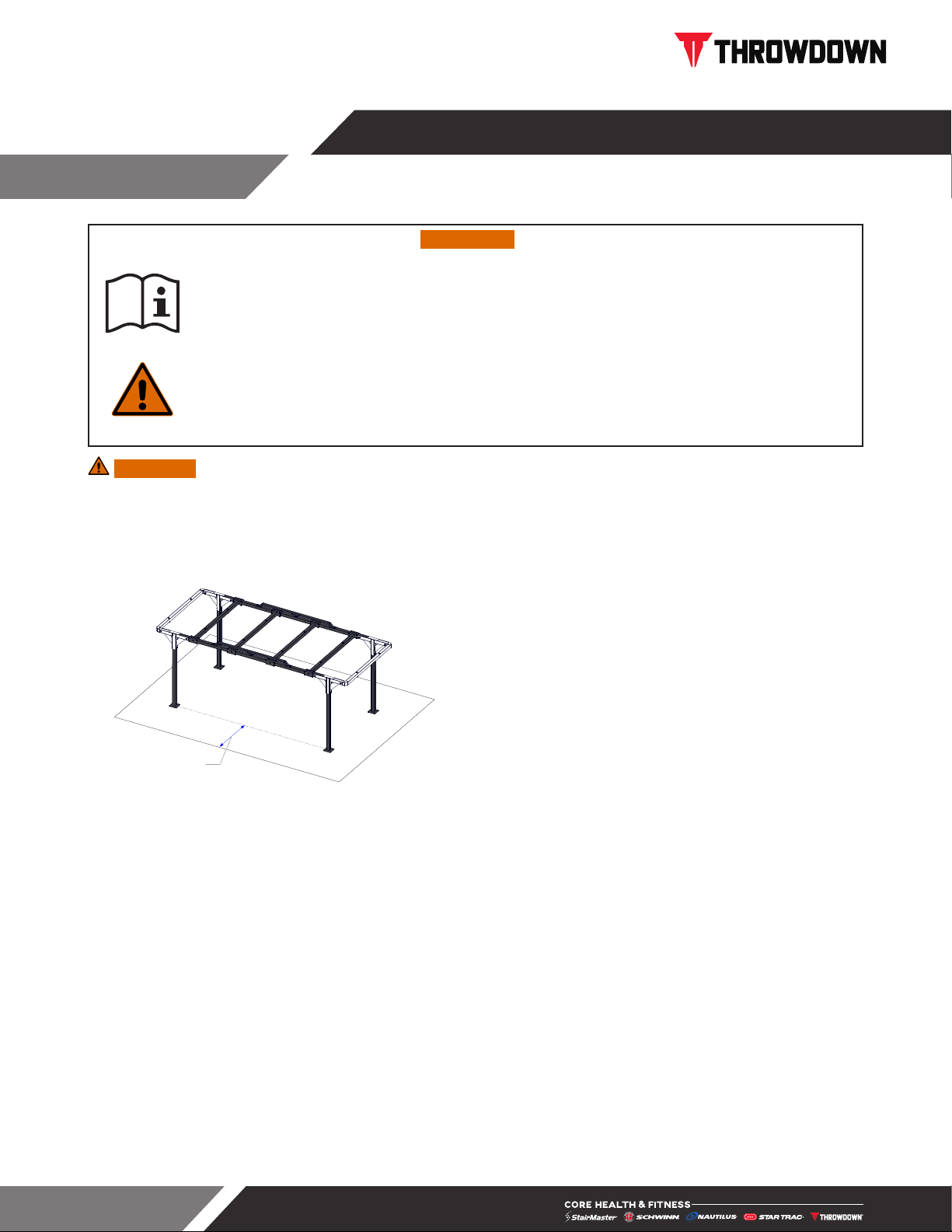
24 in (0.6 m)
Fig. 1 Required Clearance
1. Assemble and operate the unit on a solid level
surface. Position the machine with a minimum of
24 inches (0.6 meters) of clearance on one side
to allow for ease of mounting and dismounting.
Leave a minimum of 19.7 inches (0.5 meters)
between two adjacent units. These dimensions
are the recommended minimum distances.
The actual area for access and passage shall be
the responsibility of the facility and should take
into account this training envelope, Americans
with Disabilities Act Accessibility Guidelines
(ADAAG) requirements and any required local
codes or regulations (www.access-board.gov/
ada).
2. This equipment is designed for use in a
commercial gymnasium or health club. To ensure
the proper use of the equipment in a safe manner,
all users of the equipment should read this
manual before using the machine. This machine
should be made a part of your club training
program in order that the equipment is used by
your members in a safe manner as intended. In
addition to instructing the club members in the
proper use of the equipment, the club member
should obtain a complete physical examination
form their health care provider before beginning
any exercise program.
3. The safety and integrity of this machine can only
be maintained when the equipment is regularly
examined for damage and wear and repaired.
It is the sole responsibility of the owner of this
equipment to ensure that regular maintenance
is performed. Worn or damaged parts must be
replaced immediately or the equipment removed
from service until the repair is made.
4. Do not exceed the maximum allowable user
weight limit of:
• 350 lbs. (160 kg.)
5. Use only replacement components supplied by
Throwdown. Substitutes are forbidden and will
void all warranties.
6. This appliance is not intended for use by persons
with reduced physical, sensory or mental
capabilities, or lack of experience and knowledge,
unless they have been given supervision or
instruction concerning use of the appliance by a
person responsible for their safety. Keep children
under the age of 13 away from this machine.
IMPORTANT SAFETY INSTRUCTIONS