manuals.online logo
Brands
  1. Home
  2. •
  3. Brands
  4. •
  5. Cornelius
  6. •
  7. Ice Maker
  8. •
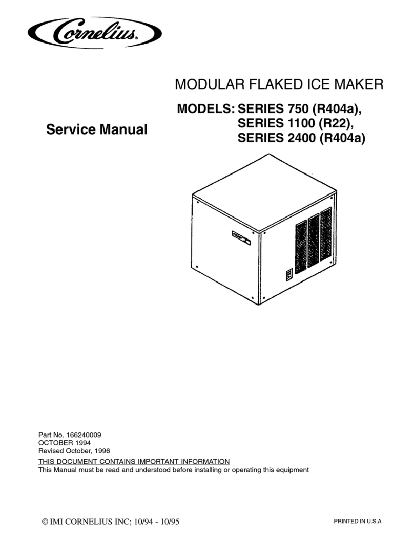
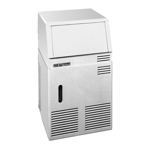
  9. Cornelius 700 - Series User manual

Cornelius 700 - Series User manual

Service
Manual
SERIES
700
MODULAR
CUBED
ICE
MAKER
6/90
161951804
INTRODUCTION
We
have strived
to
produce
a
quality product.
thus
insuring trouble-free operation.
This
manual has been prepared to
assist
servicemen and users with information
concerning installation, construction and maintenance
of
the ice making.
equipment.
The
problems of the serviceman and user have been given special
attention
in
the development and engineering
of
our icwakers.
The design has been kept simple,
If
you encounter
a
problem which
is
not covered in this manual, please feel
free
to
write or call.
We
will
be happy to assist you in any
way
we
can.
When writing, please state the model and serial number
of
the machine.
Address
a1
1
correspondence to:
-
-
A
Product
of
IMI
Cornelius lnc.
One Cornelius Place
Anoka,
MN
55303-1592
Phone 800-554-3526
Fax
61
2-422-3232
PRINTED
IN
USA
1
TABLE OF CONTENTS
INTRODUCTION
..........................
1
TABLE
OF
CONTENTS
.......................
2
..
SPECIFICATIONS
.........................
3
INSTALLATION AND START-UP
...................
4-10
REFRIGERANT CIRCUIT REMOTE CONDENSER UNITS
...........
11
ELECTRICAL CIRCUIT SEQUENCE OF OPERATION
............
12
ADJUSTMENT FOR ICE BRIDGE THICKNESS
..............
12
ADJUSTMENT AND CHECK-OUT FOR OPTICAL HARVEST
.
BIN SENSOR
...
13
WIRING AND SCHEMATIC DIAGRAMS
.................
14-16
SANITIZING AND CLEANING PROCEDURE
...............
17
WATER TREATMENT
........................
18
WINTER STORAGE
.........................
19
CLEANING THE CONDENSER
.....................
19
SERVICE ANALYSIS
........................
20-22
INSTRUCTIONS FOR REMOVAL AND RE-INSTALLATION
OF SOLID STATE CONTROL
..................
23
PARTSLIST
...........................
24
ILLUSTRATED PARTS BREAKDOWN
..................
25
REMOTE CONDENSER ILLUSTRATED PARTS BREAKDOWN
..........
26
2
Specifications
:Remocc-Air)
NOTE:
REMOTE
UNJTDESJGNED
FOR
USE
WITH
CS*
I20
REMOTE
CONDENSER
SERIES
700
ouoide
&
'F
SO'
625 353
5
30
70'
613 543
5
20
570
505
480
I
IO'
500
4
50
425
MU
VIEW
6
WIN
C
€L€ClM%L
CONNECTION
I
I
I
I
I
umou
ww
--
ar.n
METRICDIMENSIONS
SHOWN
IN PARENTHESES
L
COMPRESSOR
ELECTRICAL RATING
..........
1
H.
P.
COMPRESSOR MODEL
................
Tee. AJ-7510K
CONDENSER.
...................
Air
or water cooled
REFRIGERBNT CHARGE
...............
Air
cooled-31
02.
R502
Water cooled-24
02.
R502
REFRIGERANT CONTROL.
....
TXV
SUPERHEAT SETTING
...
VOLTAGE.
..........
INLET WATER
SUPPLY
.....
TOTAL
AMP DRAW
.......
DRAIN
STUB
....
CRANKC
AS
E
PK
E'S
S'u
<E
KE
GUL
AT
o
R
....
....
....
....
....
....
SETTING
Remote
ai
r
cooled-270
TXV
6O
3/8"
SAE
male flare
11.5
T/2"
0.0.
tube
50
PSI
208-230/
60/
1
R502
3
IN$TALLAlION
INSTRUCTIONS
A.
UNPACKING
1.
Uncrate machine and/or bin by removing the staples from around
the
bottom
of cardboard crate and
lift
off.
Remove bolts fastening the crate skid to the bottom
of
the unit.
auxiliary.legs have been purchased for the bin, they should be installed
at
this time.
2.
If
8.
LEVELING
If
legs
are
used,.adjust the leveling legs of the storage bin
until
the
unit is level and all four
(4)
legs
are insolid contact with the
floor.
Leveling
is
very important to obtain proper draining and to maintain the
;
proper level in the water pan of the ice cuber.
NOTE:
If
the bin
is
to be installed flush to the
floor,
the machine must
be sealed to the floor
with
an approved mastic such
as
Sears
13803-0
Caulk,
Dow
R.T.V.
101, 102
or
G.
E,
731,
732.
This is an
N.S.F.
requirement and
is
the responsibility
of
the installer.
c.
UNIT
LOCATION
1.
Allow
at
least
a
minimum of six
(6)
inches at the rear and side of the
ice machine for proper
air
circulation.
This unit has been designed to be installed in
an
indoor location wnich
temperatures should never exceed
100
degrees nor fall below
50
degrees.
(Temperatures above 100 degrees
will
cut the ice making capacity below
an economical level
;
temperatures below
50
.degrees
will
cause a
malfunction of thermostatic sensors.
'i
F
2.
is
clean and which can be adequately ventilated; the
air
and water
3.
The unit should be located where air circulation is not restricted.
The condenser
The unit should not be located near
a
kitchen grill.
grease vapors
will
deposit grease on the condenser.
should
always
be kept clean.
Air
which contains
D.
UNIT
SET-UP
1.
2.
3.
Take off front panel
of
machine and
remove
hardware bag or service
manual envelope with the water strainer enclosed.
Mount the ice maker to the top
of
the ice storage bin
or
adapter in
the proper position over the ice drop opening. The ice maker must
then be sealed both on the outside and the inside bottom edges with
an approved
N.S.F.
mastic such as Dow Silastic
#732,
734
or General
Electric
RTV
#101,
102.
responsibility of the installer.
This is an
N.S.F.
requirement and the
Remove shipping tape
from
evaporator curtains.
4
1NSTALLATION 1NSTRUCTlONS CONT'D.
F.
G.
MAKE
ELECTRICAL POWER SUPPLY CONNECTION
Requirements: 208-230/60hz.
1
ph.
or
22OV
50ht.
1
ph.
when
used
REFER
TO
SERIAL PLATE FOR MINIMUM CIRCUIT AMPACITY AND
MAXIMUM TIME
DELAY
FUSE
SIZE.
ALL
WIRING
MUST
CONFORM
TO
NATIONAL
AND LOCAL
ELECTRICAL
CODES.
MAKE
PLUMBING CONNECTIONS
Water supply
-
(Install per ldcal codes)
The
water
inlet connection
to
the
unit
is
a
3/8"
flare male connections
located
at
the rear
of
the ice machine.
NOTE:
should
be
installed
in
the water inlet line between the water shuteoff valve
and
the
strainer.
If
the water pressure exceeds
50
pounds,
a
water pressure recjulator'
Install
a
reducer
fitting
on
the
shut-off
valve
to
accomodate
the
water
strainer, which is supplied
with
each ice machine
and
MUST
be
used.
the
water
strainer
with
the arrow
in
the
proper
direction
of
flow
and
with
the clean
out
plug
down,
Connect
either
3/8"
or
1/2"
copper
tubing
between the water inlet
fitting
of
the
ice machine
and
the water strainer.
Install
This
is
very
important
for cleaning.
For
water cooled units,
two
water inlet connections are provided;
one
for
the ice
making
{evaporator) section
which
is located
on
the
back
of
the
machine
and
is
a
3/8"
flared connection. The other
is
for
the water cooled
condenser. The reason
for
the separate water inlet connections is
that
some
installations use
a
water tower
for
cooling
the
water used in the water-
cooled condenser
and
some installations use treatedwater (filtered)
for
the ice
making
inlet
water
connection.
(incoming)
to
the
3/8"
male flare connection
on
the
back
of
the unit
that
supplies water
to
the water regulating
valve
inside.
The setting
of
the water regulating valve
from
the
factory
should
be
120
pounds
for
R-12
units
and
250
pounds
for
R-SO2
units.
out
water lines before starting
unit.
done
at
installation.
Be sure
to
install
water
line
NOTE:
Adjustments,
if
necessary,
should
be
Always
flush
H.
DRAINS
Provide
a
suitable trapped open drain
as
close as possible
to
the
area
where
the ice maker is
going
to
be installed.
1-1/4"
trapped
open
drain.
cooled units, one
for the
storage
bin
and
one for the
Dump
Valve
drain
hose.
This
may
be
an
existing floor Or
a
Two
separate drain lines are required for air
An
additional
separate drain line
will
be required for water cooled
units
from
the outlet
of
the
condenser
coil
to
the drain.
lines
with
a
good
fail
to
the open drain.
ALL PLUMBING MUST BE INSTALLED
IN
ACCORDANCE
WITH
LOCAL CODES.
NOTE:
AND
DRAIN
LINE.
OF
CARPETS OR HARDWOODS.
Run
all
gravity drain
Iff
SOHE CASES
IT
HAY
BE
NECESSARY TO INSULATE THE WATER SUPPLY LINE
CONDENSATE DRIPPING TO THE FLOOR CAN CAUSE SERIOUS STAINING
'%
6
INSTALLATION INSTRUCTIONS CONT'D.
E.
REMOTE CONDENSERS
Remote condensers should
be
installed above the ice machine and 3n
a
level
configuration.
they
are
connected
to
the ice making unit by copper tubing
and line valves. The female
half of
the line valve ismounted on the ice
making unit and
the
remote condenser. The male half
i5
soldered on the
tube ends when tubing kits
are
provided
with
the machine.
If
tubing kits
are
not provided, the male half
of
the line valves
will
be provided in
a
valve
&it
and
the installer
will
mount them on the tubing he provides.
1.
NOTE:
STANDARD REFRIGERATION PRACTICES FOR VERTICAL LINES
TO
ASSURE POSITIVE
OIL RETURN
TO
THE CUMPKESSOR. VERTICAL LIFT TO BE NO MORE THAN
15
FEET,
WHEN VERTICAL LINES ARE INVOLVED INTHE INSTALLATION, FOLLOW',
2.
NOTE:
WE
DO
NOT RECOMMEND TUBING HUNS OF MORE THAN
40
FEET.
3.
NOTE: THE SEALS FOR THE LINE VALVES
WILL
BE FOUND INAN ENVELOPE
ON
THE REMOTE CONDENSER. MAKE SURE THEY ARE USED.
4.
NOTE: REMOVE CAP PLUGS
FROM
ALL LINE VALVES BEFORE MAKING VALVE
CONNECTIONS WITH THE SEAL.
5.
NOTE: A LOW VOLTAGE ELECTRICAL CONTROL CIRCUIT MUST BE FIELD WIRED
BEWEEN
THE
ICE MACHINE AND THE REMOTE CONDENSER RELAY. THOSE WIRES
SHOULD BE RUN WITH THE TUBING DURING INSTALLATION. REFER TO APPLICABLE
WIRING
DIAGRAMS.
6.
WHEN THE LINE VALVES ARE CONNECTED
TO
EACH OTHER THE REFRIGERANT CIRCUIT
IS
COMPLETE. EACH VALVE HALF HAS ITS OWN SHUT OFF WHICH MUST
BE
FULLY
OPENED TO ALLOW THE REFRIGERANT TO FLOW THROUGH THE SYSTEM BEFORE IT
IS STARTED.
The ice making unit utilizing
a
remote condenser
is
shipped from the factory
with the receiver holding the refrigerant charge. Additional refrigerant
may
be required upon installation depending upon the ambient conditions the remote
condenser
is
operating under, the condenser and line sizing.
A
three
way
head pressure control valve
is
used to maintain
a
relatively
consistent head pressure between
180
and
200
PSI
for
R-502
in
the
receiver in
cold
ambient conditions
to
insure
a
good harvesting or defrosting
of
the ice
slabs
on the evaporator. Because of this
valve
some
liquid refrigerant
wi
11
be held in the condenser.
NOTE:
TOTAL PRESSURE DROP
OF
14
POUNDS
OR
MORE IS WATED BETWEEN
THE
ICE MAKING
UNIT, THROUGH THE TUBING TO THE REMOTE CONDENSER, THE CONDENSER AND THE
RETURN TUBING TO THE
ICE
MAKING
UNIT.
THE
HEAD PRESSURE CONTROL
VALVE
WILL
NOT OPERATE CORRECTLY WHEN
A
The remote condenser requires
a
separate pow
supply
from
the
ice
making
unit. Refer
to
the
remote
condenser wiring diagram.
5
lNSTAlLATION
INSTRUCTIONS
CONT'D.
~~
I?
*
~
I
yrs
L*
i
a
DRAIN
CONIVECTION
INSTALLATION INSTRUCTIONS
Taking
care not to
kink
or
collapse vinyl
tubing
at
any
point, route tubes
to
any
spen,
trapped
or
vented floor drain.
Run
Wing to
drain
separately.
Dcr
not tee any drain hoses
together.
Add
drain
cubing
required to reach floor drain.
I.
ADJUSTMENT
OF
WATER LEVEL
IN
RESERVOIR
With the water supply turned
ON
and the power supply OFF'adjust
float to maintain water level%" below the support web insidereservoir
(See
Illustration Below)
-Adjust here
Water
level
Floa
t
ass
emb
1
Reservoir drain cap
WAKNINC:
Ice
bi;lkcr
~i11
noc
opcracc
properly
when
w;iCcr
supply
tempcraturc
is
below
50'F
or
above
100'1'.
pressure
must
not
exceed
SO
PSI.
IJ;itcr
supply
7
I
N
S,,,T
A
L
L
A T
I
0
N
I
N
S
T
R
U
C
T
I
0
N
S
C
0
N
T
'
D.
J.
STARTING
THE
UNIT
After the ice cuber has been unpacked and leveled and all plumbing and
electrical connections have been made, start the unit and check for proper
opera
ti
on.
A
cuber has three separate circuits:
A.
The water circuit
B.
The refrigerant circuit
C.
The electrical circuit
1.
Start checking the water circuit by making sure that there are no thread
or flare joint leaks, either outside the unit or in the compressor section.
Next check the water flow over-the evaporator and make sure that all boles
in
the water distributor are open, and that there
is
no undue splash or
loss
of
water into the ice bin.
Also check to see
if
the float valve
is
functioning properly and the
correct water level is being maintained. Re-adjust
if
necessary.
2.
Check the refrigerant circuit by making sure that the condenser fan is
running.
(Feel the casing for vibration.)
(This
will
be evident
by
air noise.)
Is
the compressor running?
Is
the evaporator getting cold?
3.
Check bin-harvest switch operation. (See proceedure
in
manual)
8
STACKING
KIT.
INSlALLATION
INSTKUClIONS
.
I,
~”.
”-
.
.C*Lt.
--
‘4
1.
2.
3.
4.
5.
6.
8.
9.
10.
11.
12.
13.
14.
15.
16.
7.
5
-
#857
screw
8/32
x
3/8
2
-
#39449
tie strap
1
-
#39450
ice
slide diverter
1
-
#39454
retainer shield assembly
1
-
#39379
interface
cable
PLEASE
SEE
ILLUSTRATIONS
FOR
REFERENCE
FOR
THE
FOLLOWING
INSTALL
PROCEDURE
After
the
bottom
unit
of
the
stack
has
been positioned
on
the
bin,
the sealing
gasket supplied
with
second
unit
must,be cemented
to
the base. Nearly
any
adhesive can be used, however
it
should
not
be water soluble.
requirement
and
the responsibility
of
the
installer. This
is
an
N.S.F.
Remove the
top
and
front panels
from
both
units.
Mount
the
unit
on
top
of
the
bottom
one
of
the stack.
to
stack
more
than
one
unit.)
Remove evaporator
curtain
cover.
N/A
(It
is
not
recommended
Put
the ice
slide
diverter
through
the
top
unit
evaporator section
and
hook
over
the
front
edge
of
the
top
unit
water reservoir.
Secure ice slide diverter
to
the
back
wall
of
the
lower
unit
with
a
provided
screw.
Insert the retainer shield
from
the
front
of
the lower unit evaporator section
and
align the holes
to
the diverter
and
support bracket
and
secure
with
the
screws provided.
Remove electrical
box
covers from
both
unit.
Remove lowest grommet
from
the left side
of
each electrical
box
.
Insert the interface cable
through
each
hole
and
insert
into
the split grommets.
&&,the cable
will
fall
across the front
of
both
machines
with
the
front
covering the cable,
Reinstall gromnets
into
electrical
box.
Plug
the interface cable
end
into
the open middle left socket
on
each solid
state
board
being
careful
to
make sure
of
a
good
connection.
Replace electrical
box
covers.
Plug
the weld
nut
hole
found
to
the right
of
the compressor
with
RTV
sealant.
Remove the screws
from
both
sides
of
both
units
and
insert the tie straps.
einstall
screws.
When reinstalling
the
front
panels,
take
care
in
the
positioning
of
the
interface cable.
9
EX
PAN
S
I
0
N
VALVE
-
EVAPORATOR
I
'$
W
ACCUM.
I I
u
CHECK
VALVE
I
U
z
RECEIVER
VALVES
'INE
&
REMOTE
CONDENSER
11
ELECTRICAL
CIRCUIT
SSN
An
L.E.D. digit display mounted on the solid state control board will show
a
status number
6,1,2,4,
&6
and
a
decimal point to indicate what is
happening
in
the operation of the unit.
The electrical. sequence of operation you will see on the digit display for
a
normal ice making cycle
will
be as follows:
The status number
0
will be shown telling you the unit
is
making ice.
solid state control
DELAYS
the start of the water pump until the evaporator
temperatures reachesm. Approximately six minutes after the start
up
in
the freeze cycle
a
decimal point will appear to the lower right
of
the
"0"
to
tell
you
that the evaporator sensor has been switched on. After
the
evaporator temperature
has
pulled
down low enough for the correct amount of
ice to be
on
the evaporator, the decimal point will begin to flash
and
stay
flashing
for
approximately
20
seconds. If evaporator stays below the set+
point,
the
harvest cycle will start. A number
"1''
on the digit display will
indicate that the machine
is
in
its harvest cycle with the hot gas valve
open. The water pump continues to operate and the water dump solenoid valve
is
now
open. The water
pump
shuts off approximately
15
seconds later after
the water reservoir
is
pumped
out.
The
PLEASE NOTE:
fan motor will be cycled on
and
off through the condenser sensor
and
solid
state control board. The fan cycling pressures
in
relation to the temperatures
sensed will be approximately
180#
for cut out
and
230#
for
cut
in
of the
fan motor.
During the freeze cycle
in
low ambient condition the condenser
ADJUSTMENT
FOR
ICE
BRIDGE
THICKNESS
An ice bridge connecting
all
cubes
is
necessary for
a
proper harvest or
discharge of cubes from the evaporator.
To increase ice "bridge" thickness carefully turn adjustment screw counter
clockwise no more than one turn at
a
time. -Wait and-checkthickness before
re-adjusting
.
HERE
n
fNCREASE
ClRCUlT
BOARD
12
I4
.
1
I-
<
ADJUSTM,EN,T
AND
CHECK-OUT
S
W
I
T
C
H'E
S
F
0
R--H-Tx-$*E
S
T
'-
B
I~N*
.m
'1
B
0
EOCE
Of
.
EVAP
W
AT
OR
PROXIM
I
TY
'
SWlTCH
ACORN
HUTS
CHECKOUT
PROCEUDRE
Turn on the ice machine and move the evaporator curtain(s)away from
the evaporator(s). The ice machine should then shutoff
in
approximitly
8
seconds.(See detail
A&B)
Slowly
let the evaporator curtain(s) move back toward the evaporator(s)
until the bottom edge
of
the curtain(s)
is
at least at the bent edge
of the water reservoir
or
closer
to the evaporator. With the curtain(s)
at that position, the machineshould start.(See detail
C)
ADJUSTMENT
PROCEDURE
If
adjustment
is
necessary,loosen acorn nutsand move proximity switch
closer to the curtain(s)and make sure the curtain
is
properly mounted.
(See detail
A
1
Re-check per above proceedure.
13
430°
Manual
Rcsct
Control
(W/C
only)
Switch
High
Pressure
pll-
I
I
RCV-1
I
+
=+:;
Optional
-
7:
Remote
-*
'*Alarm
Box
i
I
I
I
1
HornLioht Ouiet
ACAWC-700-MH
BL
I
208/230
VOLTS
60
HZ
The
solid
stote control
OEL.4
YS
the start
of
the
voter
oumD
until
the
evogorator
temperature
reache:,
20
F.
4!!&%3
Uhite
ond
block
connector
blocks
ore
'KEVED'
ond
HUST
be
inserted
correctlu
on
circuit
boord-pm
p$
14
PART
HO
39149
fiRTUORK
no.
50492
REV.
H
AD
rankcase
Heater Compressor
Comoressor
I
Outlet
Box
1
-
Pump
Water
*
BL
-
I
I
-rAlarm
Box
,
RCV-1
Rev.
E
II
ORRD
4)))
#
:p
To
stacked
Unit*DC2
I
Control
DCZ
if
required
I
Horn
Light
Ouiet
Switch
I
Switch
432=yDC4
rUH
I
I
RC-700-MH
The solid state
control
DELAYS
the
start
of
e
the
voter
pump
until the
evogorotor
temperature
reoches
20
F,
Uhitr
and
block connrctor blocks
ore
'KEYED'
ond
RUST
be
inserted
correctlu
on
circui
t
board--
D
PRRT
NO.
39362
f3ATUORK
NO.
50498
REV.
H
15
r
RD
I
Compressor
Compressor
I
RD
ON
430"
Manual
Reset
High
Pressure
Control
(W/C
only)
YYY
@
BL
Water
Pump
II.
Sensors
I
I,
6
Fan
motor
(
A/C
only)'
I
Dump
+
\-
-
-5
-,
.
Optional
G!
Remote
Horn
light
Quiet
Switch
1
230
VOLTS
SO
HZ
ACtiWC-7OO-MH
The
aolid
atate
control
DELA
Ys
the
Btort
of
the voter
DumD
until
the
evagorator
temperoture
reachea
20
F.
l4!Eis
Uhite
ond
block
connector
blocks
ore
'KEYED"
ond
RUST
be inserted correct
lu
on
circuit
board.
16
PART
fl0.
39341
RRTUORK
NO.
5049'7
REU.
C
1.
2.
3.
4.
5.
6.
7.
8.
9.
10.
SANITIZING
AND
CLEANING
PROCEDURE
Remove front
panel
to
gain
access
to
the
on-off-clean switch.
Push
switch
to
"cleann
and
allow
the
ice
on
the
evaporator
to
release
or melt
away.
Remove
all
ice
from
storage
bin.
Mix
a
sanitizing solution
of
1/4
02.
"Calgon
Ice
Machine
Sanitizer"
to
one gallon
of
water,
Using
a
non-metallic
bristle
brush scrub the following:
a.
b.
Inside surfaces of
ice
bin including
top
and
door.
Inside surfaces
of
the
icemaker
to
include
evaporator
section in
the
ice
machine including the
top,
front
panel
and evaporator splash curtain,
c
c,
Make sure splash curtain
is
correctly positioned.
Add
2
oz.
of
"Calgon Nickel-Safe
Ice
Machine Cleaner"
directly into
water
reservoir.
45
minutes.
Circulate
for approximately
Remove cap from reservoir
drain
and
allow
cleaner
to
drain
away.
Replace
cap.
Fill
reservoir with clean
fresh
water,
circulate for
approximately
1
minute,
allow
water
to
drain away.
Remove
cap
from reservoir drain and
Repeat
three
times.
Flush
all
waste
water
from
ice
storage
bin
with
clean
fresh
water
.
Push switch
from
ncleann
to
"on"
position.
Replace
front
panel.
Adj
us
t
here
Water
level
Floar
assembly
Reservoir
drain
cap
\
17
WATER
TREATMENT
Automatic ice-making machines can quit working for any number of reasons,
mechanical
,
electrical or faulty refrigeration, but
water
problems foul them
up faster than almost anything else. While ice machines vary in design, you
can apply these water treatment tips to all of them.
1.
START
WITH
THE
WATER
The mlneral content of water varies
in
different areas and as the
chart shows, high hardness and alkalinity counts combine to form
insoluble calcium carbonate or lime scale.
If
this condition
is
constant, the intake water must be treated constantly to pre’vent
scale formation in the ice machine.
2.
PREVENT LIME SCALE
FORMATION
d
We recomnend the installation of a Calgon Microment Feeder on the
incoming water line.
with
a capacity of
400-450
lbs. per day.
Fill
the feeder with 6R
Micromet, the slowly soluble poly-phosphate which lasts six months
before renewing the
8-02.
charge.
No.
X-8B
Feeder
is
recommended for ice machines
Constant treatment with
6R
Micromet
will
control lime scale and
prevent minerals from sticking to the freezing surfaces in ice
machines.
ice cubes, efficient, automatic production.
Result
-
smooth movement of ice slabs, good harvest of
3.
REMOVE
OBJECTIONABLE TASTE
OR
ODOR
If
the bad taste or odor
is
traceable to the water source, install a
Calgon Fine Carbon Filter to the incoming water line. The No.
1-1/28
Fine Carbon Filter
is
ideal for machines making up to
500
pounds
of
ice per day and
will
remove bad taste, odors, and problems caused
by chlorine in the water supply.
cause odor problems and these growths can be removed by the use of
liquid ice machine cleaner.
In
some instances, slime growths may
4.
SERVICE
REGULARLY
A
service program
to
clean the ice machine
at
regular
intervals and
check on filter and feeder charges is important.
will
assure adequate water treatment, reduce emergency calls and aid
in
the trouble-free performance of automatic
ice
making machines.
In the long run,
it
18
I
1
I.
WIN,TER S?QRAG,E
If
the unit is to be stored in an area where
the
temperature
will
drop
below freezing,
it
is
most important that all water lines be drained to
prevent them
from
freezing and possible rupture.
I
To
blow out the
water
line, disconnect the
water
supply
at
the cabinet
inlet and use air pressure to force the water into the water reservoir
pan. This can then be removed from the water pan.
CLEANING THE CONDENSER
In
order to produce
at
full capacity, the refrigeration condenser must be
kept clean. The frequency
of
cleaning
will
be determined by surrounding
condition.
every
two
months.
Remove
the
lower front panel
of
the machine. With
a
vacuum cleaner, remove
all accumulated dust and lint that has adhered
to
the finned condenser.
A
good maintenance plan calls for an inspection at least
#
CAUTION: CONDENSER COOLING FINS ARE SHARP. USE CARE WHEN CLEANING.
1.
If
the condenser is being cleaned
from
the back
of
the machine, remove
all accumulated dust, dirt etc., that has adhered
to
the finned
surface
with
a vacuum cleaner.
2.
If
the unit
is
being cleaned from the front, remove lower panel, turn
the power switch off and blow through the finned surface of the
condenser past the fan blade to remove accumulated dust, etc.
%%4
19

Other Cornelius Ice Maker manuals

Cornelius XTREME 631814001 Setup guide

Cornelius

Cornelius XTREME 631814001 Setup guide

Cornelius WM600 Operating instructions

Cornelius

Cornelius WM600 Operating instructions

Cornelius WCC1401-A Series User manual

Cornelius

Cornelius WCC1401-A Series User manual

Cornelius WM600 User manual

Cornelius

Cornelius WM600 User manual

Cornelius Nordic CCU0300 Series User manual

Cornelius

Cornelius Nordic CCU0300 Series User manual

Cornelius Series 200 User manual

Cornelius

Cornelius Series 200 User manual

Cornelius 500 - Series Manual

Cornelius

Cornelius 500 - Series Manual

Cornelius ED150 "K" Style Lid Kit User manual

Cornelius

Cornelius ED150 "K" Style Lid Kit User manual

Cornelius IMD300-15A User manual

Cornelius

Cornelius IMD300-15A User manual

Cornelius I Series Installation guide

Cornelius

Cornelius I Series Installation guide

Cornelius CMP600-30A User manual

Cornelius

Cornelius CMP600-30A User manual

Cornelius IMD GLACIER 500-30 User manual

Cornelius

Cornelius IMD GLACIER 500-30 User manual

Cornelius ICE MAKER User manual

Cornelius

Cornelius ICE MAKER User manual

Cornelius P/N 620028801 User manual

Cornelius

Cornelius P/N 620028801 User manual

Cornelius ED-300 User manual

Cornelius

Cornelius ED-300 User manual

Cornelius Nordic CCM1848 Guide

Cornelius

Cornelius Nordic CCM1848 Guide

Cornelius CCM CCU Installation and operation manual

Cornelius

Cornelius CCM CCU Installation and operation manual

Cornelius EVAPORATOR CONVERSION KIT WCC700 User manual

Cornelius

Cornelius EVAPORATOR CONVERSION KIT WCC700 User manual

Cornelius Nordic CCM1448 Guide

Cornelius

Cornelius Nordic CCM1448 Guide

Cornelius Enduro-300 IntelliCarb User manual

Cornelius

Cornelius Enduro-300 IntelliCarb User manual

Cornelius Xtreme 322 Series User manual

Cornelius

Cornelius Xtreme 322 Series User manual

Cornelius UC 701 Series Manual

Cornelius

Cornelius UC 701 Series Manual

Cornelius CCM0330 Installation and user guide

Cornelius

Cornelius CCM0330 Installation and user guide

Cornelius D3030-1 User manual

Cornelius

Cornelius D3030-1 User manual

Popular Ice Maker manuals by other brands

KitchenAid KUIC18NNSS0 parts list

KitchenAid

KitchenAid KUIC18NNSS0 parts list

Scotsman MDT5N40A-1B manual

Scotsman

Scotsman MDT5N40A-1B manual

U-Cube POLAR ICE TRAY user manual

U-Cube

U-Cube POLAR ICE TRAY user manual

Costway EP24483US user manual

Costway

Costway EP24483US user manual

KitchenAid KUIS18PNTB0 parts list

KitchenAid

KitchenAid KUIS18PNTB0 parts list

Swann SI-100E instruction manual

Swann

Swann SI-100E instruction manual

Hoshizaki IM-500SAB instruction manual

Hoshizaki

Hoshizaki IM-500SAB instruction manual

emerio IM-111502 instruction manual

emerio

emerio IM-111502 instruction manual

ALPATEC MG 6 user manual

ALPATEC

ALPATEC MG 6 user manual

Hoshizaki CUBELET ICEMAKER/DISPENSER DCM-750BAH-OS parts list

Hoshizaki

Hoshizaki CUBELET ICEMAKER/DISPENSER DCM-750BAH-OS parts list

Hamilton Beach Ice Shaver owner's manual

Hamilton Beach

Hamilton Beach Ice Shaver owner's manual

KitchenAid 4KUIS185S installation instructions

KitchenAid

KitchenAid 4KUIS185S installation instructions

Hoshizaki KM-1200MAE parts list

Hoshizaki

Hoshizaki KM-1200MAE parts list

Ice-O-Matic ICE0805 Series Specification sheet

Ice-O-Matic

Ice-O-Matic ICE0805 Series Specification sheet

Kool-It KOU-70-AB user manual

Kool-It

Kool-It KOU-70-AB user manual

Follett Maestro Plus MCC425A BS Operation and service manual

Follett

Follett Maestro Plus MCC425A BS Operation and service manual

Hoshizaki FM-481AGE-HC installation manual

Hoshizaki

Hoshizaki FM-481AGE-HC installation manual

Maxx Ice MIM250 Service, installation, and instruction manual

Maxx Ice

Maxx Ice MIM250 Service, installation, and instruction manual

manuals.online logo
manuals.online logoBrands
  • About & Mission
  • Contact us
  • Privacy Policy
  • Terms and Conditions

Copyright 2025 Manuals.Online. All Rights Reserved.