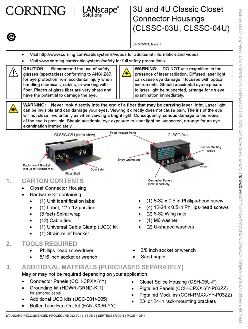
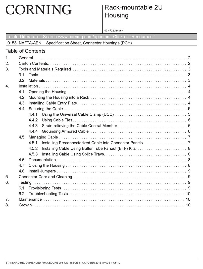
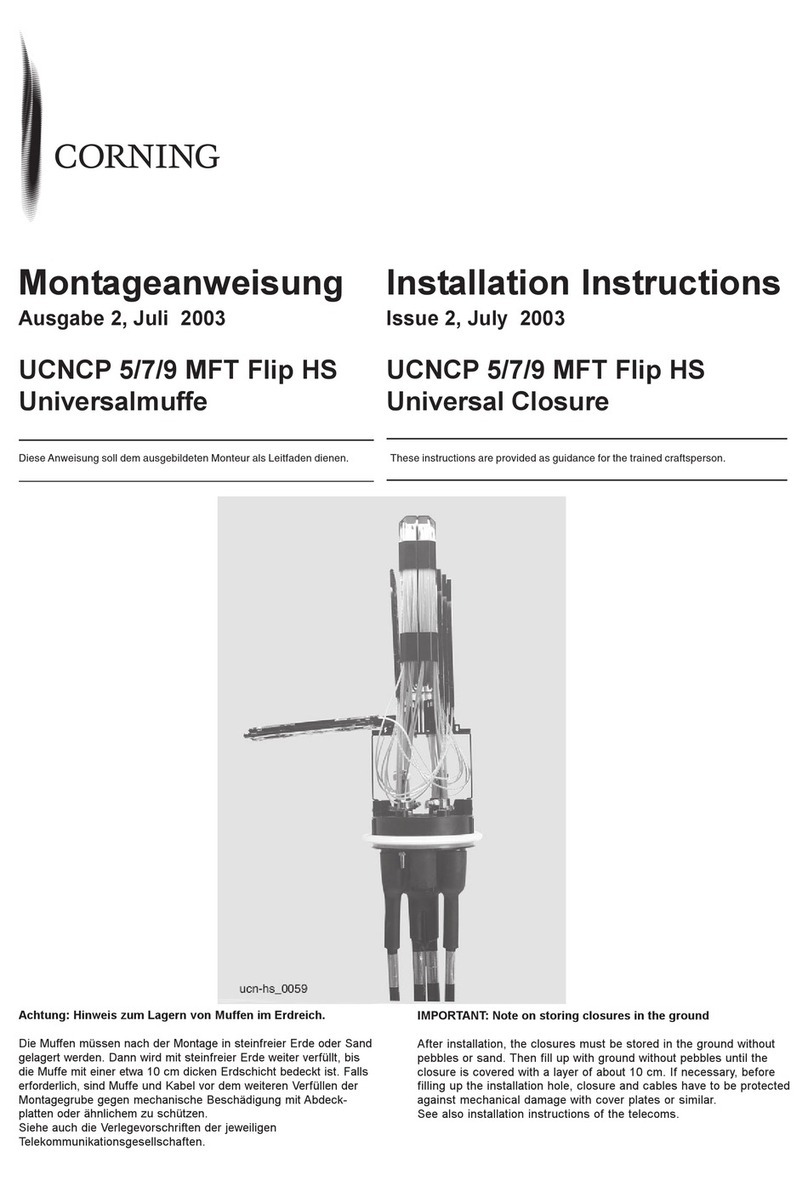
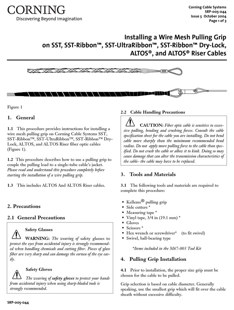
CORNING X75 8000 Series User manual

Subject to change without notice.Subject to availability.
Issued byCorning Cable Systems GmbH & Co.KG · Profilstraße 4 · D-58093 Hagen · Germany
Tel.+49-2331-3571145, 3571146, 3571155 or 3571402 · Fax +49-2331-3571309
© 2001 byCorning Cable Systems GmbH & Co.KG revision:06/01
Printed in GermanyOrder No.:S46999-L6063-P451

Important
Please read these operating instructions carefully to ensure that your fusion splicer func-
tions flawlessly, and that it fulfills your expectations. Perform all necessary service and
maintenance work on your fusion splicer regularly with the help of this manual.At most
care should be exercised in order to prevent damage.
If you have any queries whatsoever, please contact the trained specialists at your service
center.
Improper or insufficient maintenance may impair the operating performance of your fusion
splicer.
All liability borne by the manufacturer, as well as the guarantee, are null and void if the
fusion splicer is tampered with by unauthorized persons.
NOTE For reasons of clarity, these operating instructions do not provide detailed information for
all versions of the product and cannot, therefore, take every possible installation, operation
or maintenance situation into consideration.If you require further information, or if particu-
lar problems arise which are not covered in enough detail in the operating instructions, do
not hesitate to contact the Corning Equipment Service Department for the necessary infor-
mation.
These operating instructions do not form part of a previous or existing agreement, commit-
ment or legal relationship, nor are they intended to amend or modify any such arrange-
ment. All obligations on the part of Corning arise exclusively from the relevant sales
contract which also contains the only valid and comprehensive warranty conditions.The
operating instructions neither extend nor limit the contractual warranty conditions.
Addresses
If your fusion splicer requires service please send it to:
Siemens Dematic AG
SD EA 32 / Geräteservice
Warenannahme
Rupert-Mayer Straße 44
D-81359 Munich, Germany
Tel. +49-89-72222068
Fax +49-89-72248324
If you have technical questions or questions regarding our training program, please con-
tact:
Corning Cable Systems GmbH & Co. KG
Abteilung PLM TS
Profilstraße 4
D-58093 Hagen, Germany
Tel. +49-2331-3571145, 3571146, 3571155 or 3571402
Fax +49-2331-3571309

Definitions forTerminology used inWarnings
The following definitions apply to the terminology used in the warnings:
Danger
In these operating instructions, as well as in warnings on the products themselves, this
term means that death, serious injury or substantial property damage will result if the rele-
vant precautions are not observed.
Warning
In these operating instructions, as well as in warnings on the products themselves, this
term means that death, serious injury or substantial property damage may result if the rel-
evant precautions are not observed.
Caution
In these operating instructions, as well as in warnings on the products themselves, this
term means that slight injury or property damage may result if the relevant precautions are
not observed.
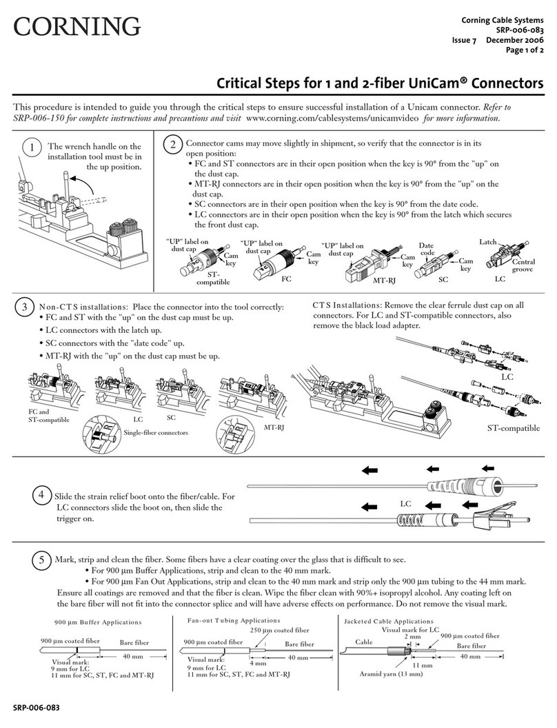
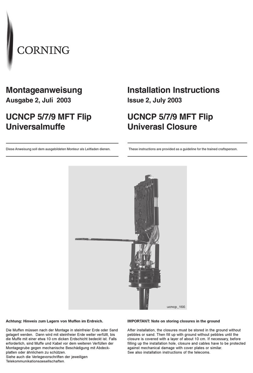
Note
In these operating instructions, this term makes reference to important information about
the product, or the relevant part of the operating instructions to which particular attention
must be paid.
Qualified
Personnel
In these operating instructions, as well as in warnings on the products themselves, this
term means persons who are familiar with start-up, operation and maintenance of electri-
cal equipment, and who are suitably qualified for the work they perform.

DANGER When electrical equipment is operated, certain parts of such equipment are bound to
reach hazardous voltage levels. If the appropriate warnings are not observed, serious
injury or property damage may occur.Only suitably qualified personnel should work on this
equipment or in its vicinity.Such personnel must be entirely familiar with all of the warnings
and maintenance procedures included in these operating instructions.Flawless, safe oper-
ation of this device is only possible if it has been properly transported, stored, assembled,
and installed, as well as correctly operated and maintained.


X75 Fusion Splicer
Password Request
Operating Instructions
revision: 06/01
Password Request
Activating the
Password
Request
The fusion splicer must be opened in order to activate or deactivate the password request.
DANGER The fusion splicer or electrically operated accessories may only be opened by suitably
qualified personnel.
Switch the fusion splicer off and disconnect it from the power supply (power supply plug
and 12V battery supply)!
Two phillips head screws are located on the left of the housing and two on the right.These
must be removed in order to open the housing.The switch for activating and deactivating
password request is on the printed circuit board visible once the housing has been opened
(switch in ON position: password request activated).
If password request is deactivated, the stored password is deleted as soon as the fusion
splicer is switched on again. However, if you reactivate password request without having
previously switched the fusion splicer on and off, the old password is retained.
No password is stored when request is reactivated.A new password must therefore first be
defined.
Entering the
password
A password consists of an arbitrary sequence of five input keys.If you attempt to change a
parameter when password request is activated, the message “Enter Password” appears.If
an incorrect password is entered, the parameter change is not saved to memory.This also
applies to a change of password, i.e.a new password cannot be defined unless the current

Operating Instructions
revision: 06/01
X75 Fusion Splicer
Password Request
password is known.To redefine the password, select the parameter “Password” and pro-
ceed according to the following flow chart.
Change password? Enter password?
Only if password already exists
Enter new password
Confirm password Password wrong
Operator menu

X75 Fusion Splicer
X75 Fusion Splicer, Overview
Operating Instructions
revision: 06/01 1-1
1 X75 Fusion Splicer, Overview
Contents Page
General..........................................................................................................................................................1-2
Equipment Overview .....................................................................................................................................1-3
Splicing Unit ...........................................................................................................................................1-4
L-PAS Video Image Evaluation System.................................................................................................1-4
Monitor ...................................................................................................................................................1-5
Keyboard................................................................................................................................................1-5
Terminals for Additional Functions.........................................................................................................1-6
Technical Data...............................................................................................................................................1-7

Operating Instructions
revision: 06/01
X75 Fusion Splicer
X75 Fusion Splicer, Overview 1-2
General
The X75 Fusion Splicer is suitable for producing reliable, low-loss splices of optical fibers.
It can be used for all common single-mode and multimode fibers with a cladding diameter
of 125
µ
m and coating diameters of 250 to 900
µ
m.
Due to its L-PAS (Lens-Profile Alignment System) video image evaluation with two CCD
cameras and an optic system, the X75 Fusion Splicer enables the fiber alignment, end
face quality inspection, fiber offset detection, contamination detection and splice loss esti-
mation during fully atomatic splice procedure by the press of one button.

X75 Fusion Splicer
X75 Fusion Splicer, Overview
Operating Instructions
revision: 06/01 1-3
Equipment Overview
2
3
5
4
6
1
4
1 Power Supply Port
2 Heat-Shrink Oven Socket
3 Splicing Unit
4 Keyboard
5 Monitor
6 Ports for Additional Functions

Operating Instructions
revision: 06/01
X75 Fusion Splicer
X75 Fusion Splicer, Overview 1-4
Splicing Unit
L-PAS Video
Image Evalua-
tion System
The X75 Fusion Splicer is equipped with the L-PAS Video Image Evaluation System.
The position and quality of the fiber ends are evaluated by a video image evaluation sys-
tem which uses two cameras and a magnifying optic.
By evaluating the video image of both fiber views, the fiber endface quality, dirt and
mechanical damages as well as fiber offset are detected, a fast fiber alignment is enabled
and the splice loss is estimated.
The image of both fiber views is shown simultaneously on the monitor.
1 Electrode Flap
2 Electrodes
3 Fiber guides (silicon v-grooves)
4 Holder flaps
5 Clamping flaps
1
2
3455
4

X75 Fusion Splicer
X75 Fusion Splicer, Overview
Operating Instructions
revision: 06/01 1-5
Monitor
The LCD monitor shows the fibers from two different perspectives (along the X andY
axes).
Keyboard
The keyboard consists of 6 keys with the following functions:
Enter key:The displayed operation is performed or the previously entered value is
acknowledged.
Open or exit parameters menu.
Scroll back to previous line.
Scroll forward to next line.
Increase displayed value.
Reduce displayed value.

Operating Instructions
revision: 06/01
X75 Fusion Splicer
X75 Fusion Splicer, Overview 1-6
Terminals for
Additional
Functions
Serial Interface Splicing parameters or the contents of the splice data memory can be read out to a printer
or a computer via the RS 232c serial interface.The serial interface at the fusion splicer is
configured for use with the XON/OFF protocol. Asynchronous data transmission is accom-
plished with one start bit, eight data bits and one stop bit.The parity bit is not used.
Video Output You can connect a standard European monitor (CCIR, 625 lines) with an input impedance
of 75
Ω
or higher to this output.Use a commercially available coaxial cable with RCA plug.
1 RS 232c Serial Interface
2 Video Output
12

X75 Fusion Splicer
X75 Fusion Splicer, Overview
Operating Instructions
revision: 06/01 1-7
Technical Data
Fiber Requirements: cladding diameter: 125
µ
m
coating diameters: 250 to 900
µ
m
Fiber Display: 140 mm (5.5“) LCD monitor
Magnification: approximately 100 times
Fiber Alignment: fully automatic, automatic and manual
(Z axis)
Typical splice loss for identical stand-
ard single-mode fibers: < 0.05 dB
Tensile Test: selectable, 2.5 N
Number of Splicing Programs: 3 fixed programs
4 special programs
10 user programs
Video Output: CCIR Output (75
Ω
)
Operating Temperature: -5˚C to 45˚C
Storage Temperature: -40˚C to 70˚C
Dimensions Basic Unit (L x W x H): 208 x 185 x 100 mm
Weight: 2.1 kg

Operating Instructions
revision: 06/01
X75 Fusion Splicer
X75 Fusion Splicer, Overview 1-8

X75 Fusion Splicer
Preparatiss
Operating Instructions
revision: 06/01 2-1
2 Preparatiss
Contents Page
Putting the Fusion Splicer into Operation ......................................................................................................2-2
Supply Power.........................................................................................................................................2-2
Switching the Fusion Splicer On ............................................................................................................2-2
Preparing the Fiber Ends...............................................................................................................................2-4
Stripping the Coating..............................................................................................................................2-4
Cleaning the Fiber..................................................................................................................................2-5
Cleaving the Fiber..................................................................................................................................2-5
Inserting the Fiber..........................................................................................................................................2-6
250
µ
m Coating......................................................................................................................................2-6
Other Coating Diameters........................................................................................................................2-7
Adjusting Monitor Brightness.........................................................................................................................2-7
Checking the Fiber End Faces.......................................................................................................................2-8

Operating Instructions
revision: 06/01
X75 Fusion Splicer
Preparatiss 2-2
Putting the Fusion Splicer into Operation
DANGER In order to assure safe operation, the fusion splicer must be placed into operation and
properly operated by qualified personnel under consideration of the warnings included in
these operating instructions.Non-observance may lead to death, severe bodily injury or
substantial property damage.
Supply Power
Connect the fusion splicer to supply power (see operating instructions for the power
pack or the rechargeable battery).
Switching the
Fusion Splicer
On
- Before switching the fusion splicer on, make sure that both electrodes are properly
seated (see »Replacing the Electrodes« on page 6-18).
DANGER Never switch the fusion splicer on without electrodes.The fusion splicer may otherwise
be damaged!
- Press the key to switch the fusion splicer on.
- After switching on, the software version installed is dis-
played at the monitor and a self-test is performed.The elec-
trodes are automatically cleaned if selected with a cleaning
arc which is carried out with closed electrode flap.
- A status report showing selected settings is displayed at the
monitor.
Table of contents
Other CORNING Cables And Connectors manuals

CORNING
CORNING Lanscape Solutions CLSSC-03U User manual

CORNING
CORNING SST Instruction Manual

CORNING
CORNING SRP-004-067 User manual

CORNING
CORNING Gold 000301T4180002M User manual

CORNING
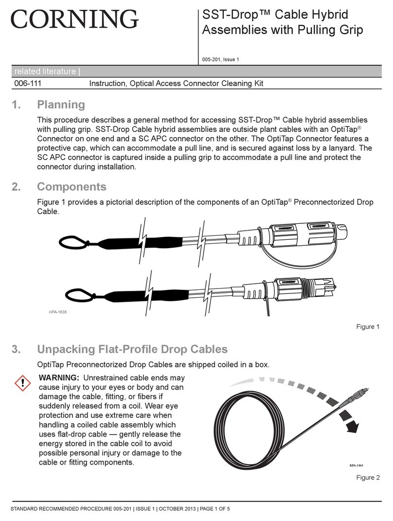
CORNING SST-Drop User manual

CORNING
CORNING UCNCP 5 MFT Flip HS Series User manual

CORNING
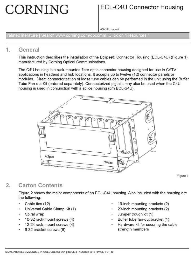
CORNING ECL-C4U User manual

CORNING
CORNING Crimplok+ Connector 8700 APC SM 250/900 mm User manual

CORNING
CORNING ClearCurve SRP-005-065 User manual

CORNING
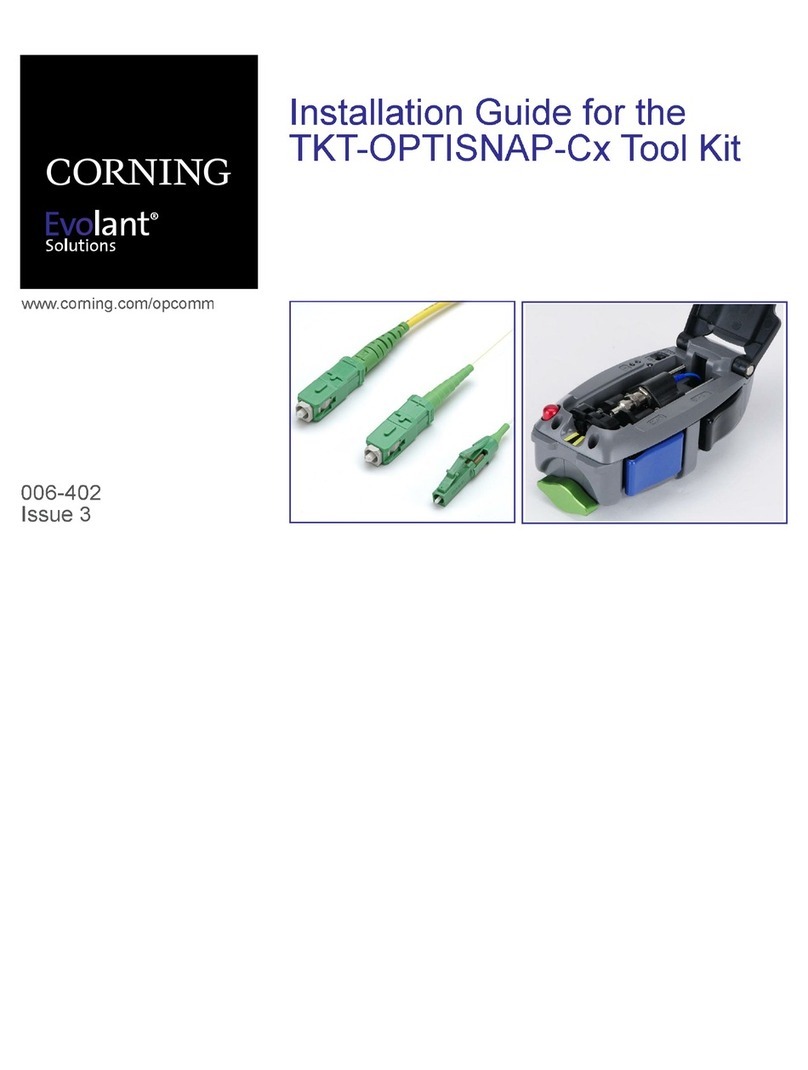
CORNING Evolant TKT-OPTISNAP-Cx User manual