STANDARD RECOMMENDED PROCEDURE 000-274 | ISSUE 4 | AUGUST 2016 | PAGE 2 OF 7
NOTE: This procedure assumes that the EDGE™ solution housing is on a work surface or has been
installed into the frame.
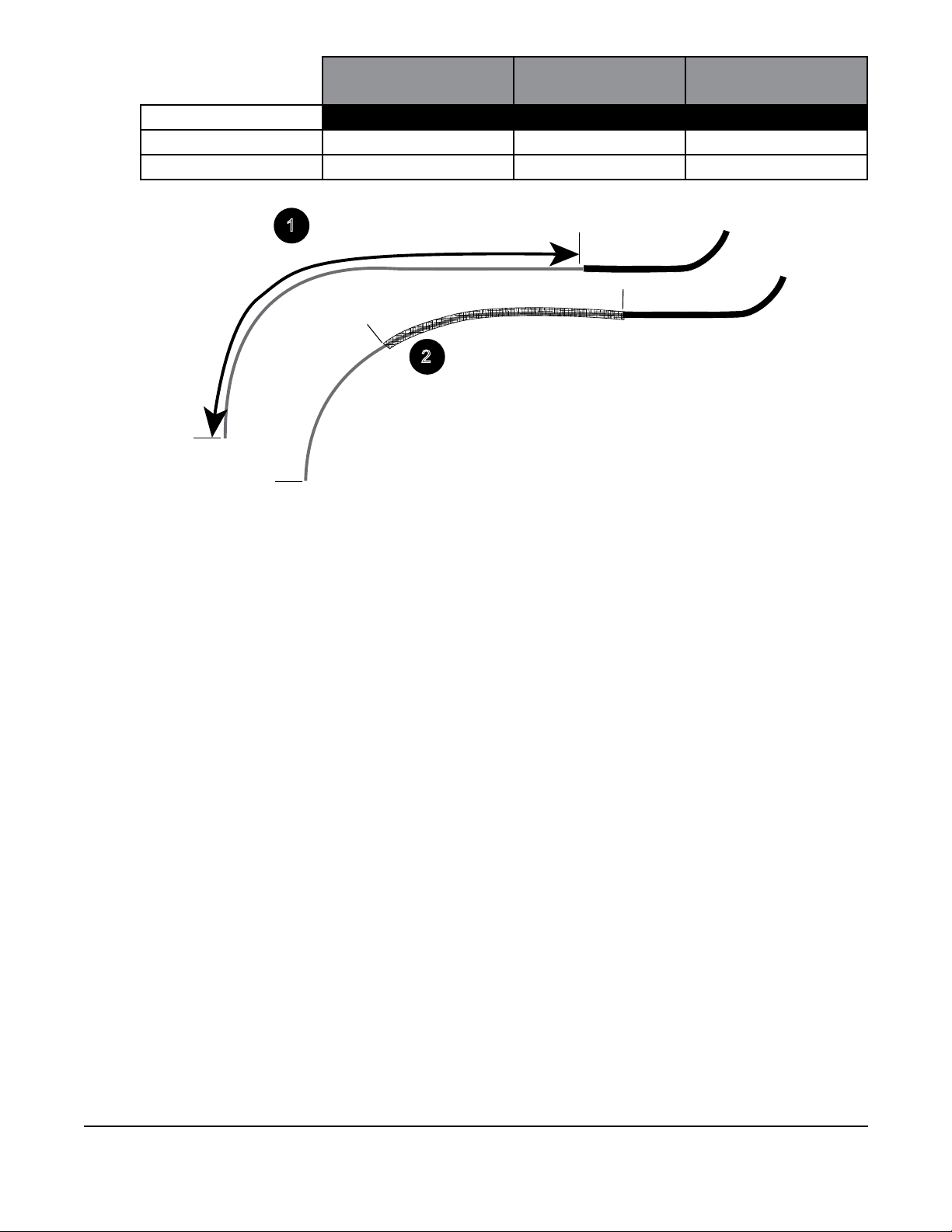
Fiber Inside Cassette Jacketed Subunit Total Outer Jacket
Strip Length
For Splicing 33 in 33 in 66 in
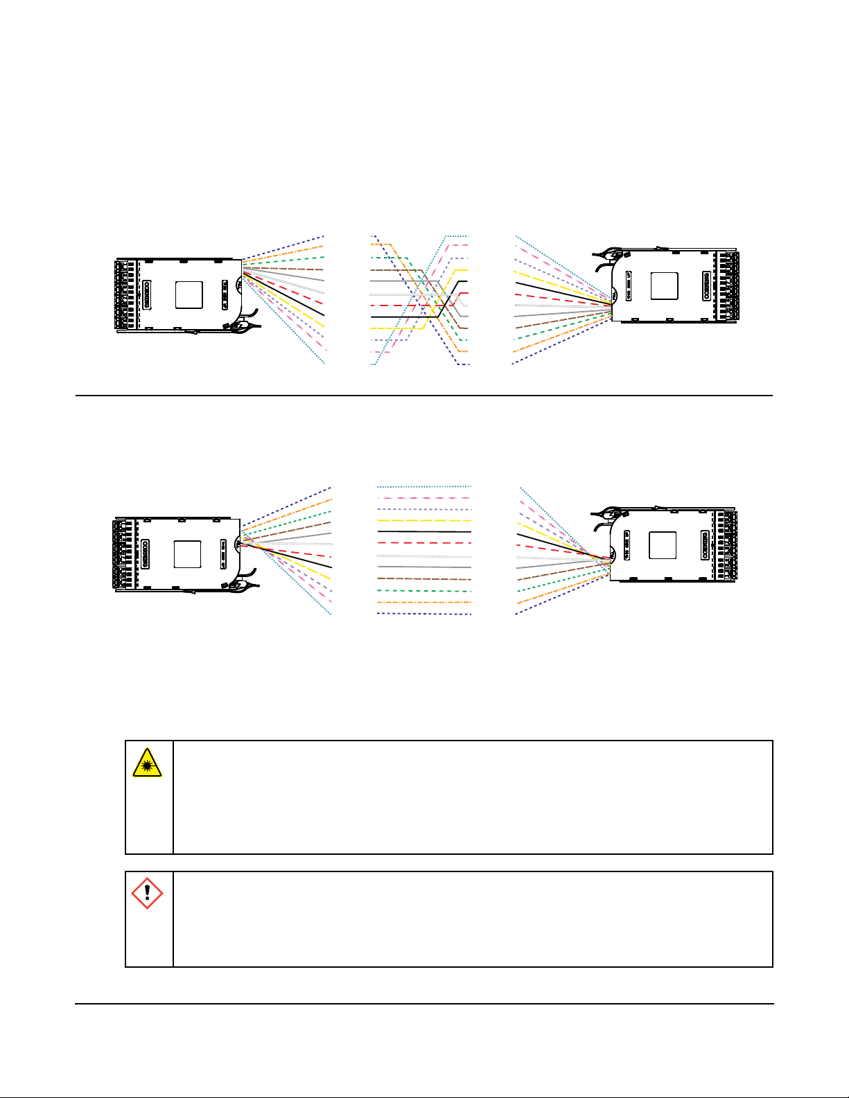
Figure 1
Step 1: Determine from which side the cable will enter the housing (Figure 1). Measure
and mark the length specied in the table above from cable end and strip cable per
instructions provided with the cable or per standard company practices. Then mark
the subunit at the required length from the end of the cable. This mark denotes the
point at which the bers will enter the cassette.
Step 2: Strip the subunits from the mark to the end of the subunit.
NOTE: If additional protection for the ribbon or 900 µm subunits is desired, install 33 in (0.84 m) of
braided tubing over the ribbons or 900 µm bers beginning at the point where the jacket is
strain-relieved in the cradle.
4. Splice Cassette Installation
WARNING: Never look directly into the end of a ber that may be carrying laser
light. Laser light can be invisible and can damage your eyes. Viewing it directly
does not cause pain. The iris of the eye will not close involuntarily as when viewing a
bright light. Consequently, serious damage to the retina of the eye is possible. Should
accidental eye exposure to laser light be suspected, arrange for an eye examination
immediately.
CAUTION: Cleaved or broken glass bers are very sharp and can pierce the skin
easily. Do not let these pieces of ber stick to your clothing or drop in the work area
where they can cause injury later. Use tweezers to pick up cleaved or broken pieces
of glass bers and place them on a loop of tape kept for that purpose alone. Good
housekeeping is very important.
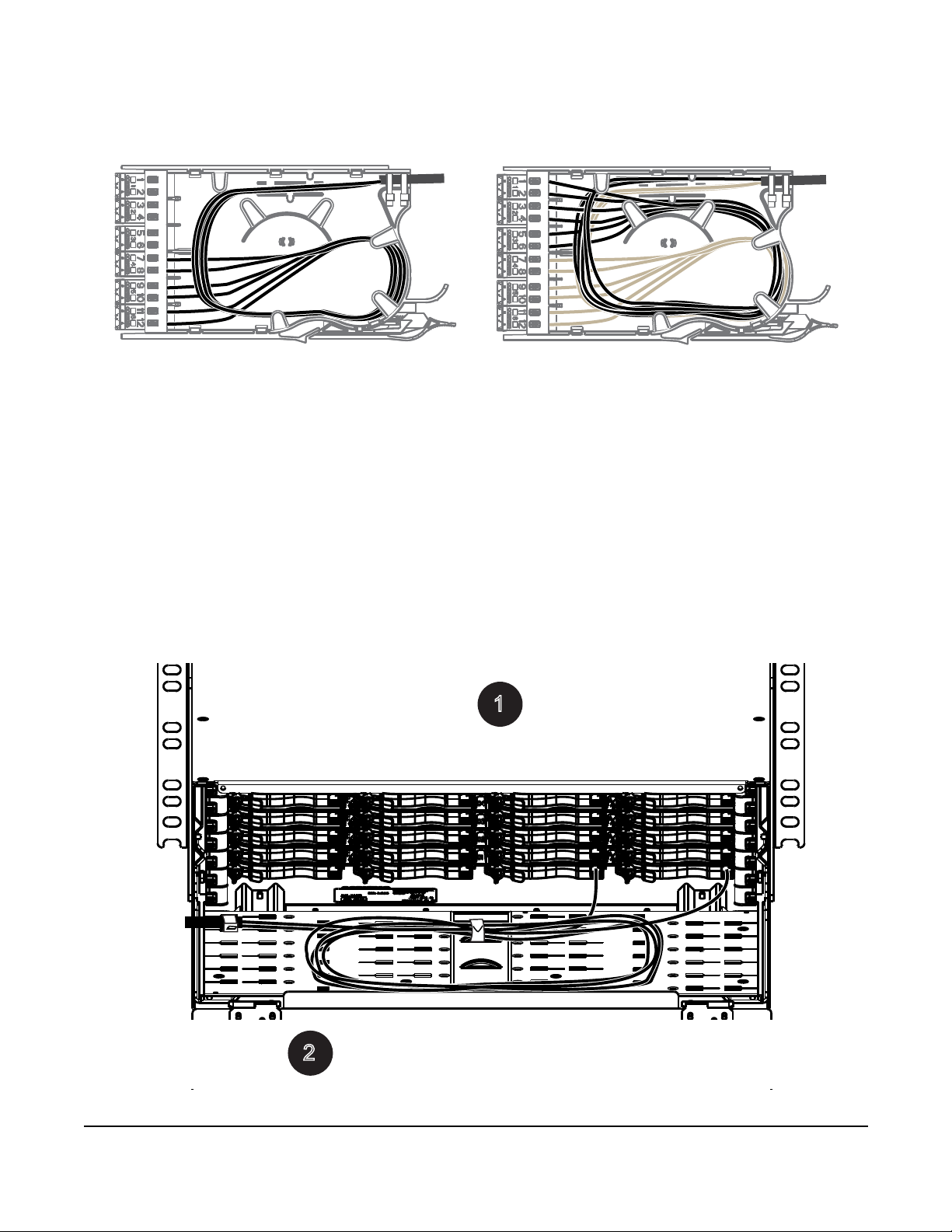
Step 1: Bring the subunits into the splice cassette. If using loose-tube cable, it is recomended
to use friction tape over the end of the buffer tube.
Step 2: Secure subunit with cable ties as it enters the cassette (Figure 2).
Strip jacket(s) per lengths specified in table above for your application.
(Optional) If cable is ribbon or single-fiber, install
33 inches (0.84 m) of braided or protective tubing,
leaving length required for splicing inside the
cassette or field-terminating the fiber.
1
2
3
3
i
n
c
h
e
s
3
3
i
n
c
h
e
s
b
r
a
i
d
e
d
t
u
b
i
n
g
TPA-4350A